Cameron has put together an excellent ‘how to’ on model railroad turnouts:
“Dear Al,
It’s been a while since my last post.
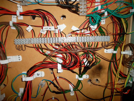
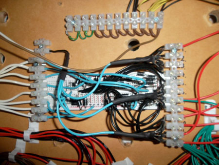
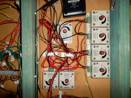
I have spent a lot of time over the last couple of months lying under the layout with wire cutters in one hand and a soldering iron in the other. There is now a big mess of wires under table that reflect a lack of planning on my part. I bit embarrassing but part of the process.
Following is a couple of tips on electrifying points on a layout that might be of use to a few of your readers.
Turnouts and Motors
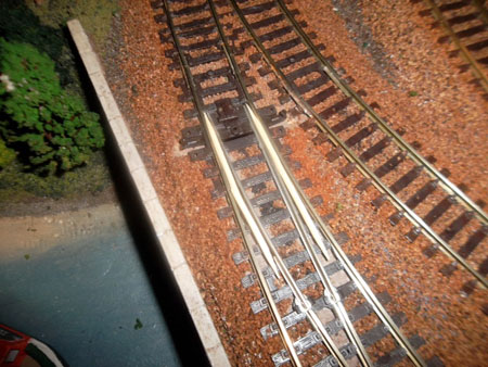
Before I laid the track I drilled holes in the right locations for the point switch rods. I would do this again regardless of whether I planed to electrify the points or not. You never know how hooked you are going to get on this hobby.
I used Peco turnout motors which have been quite good. Rather than using the propriety plastic adapters I simply bent out the fixing prongs to act as a fixing lug. Perhaps a bit rough but a lot of modelers seem to use this method.
They all run off a 4amp 14v power supply which is not at the top end for this type of point but has been reliable.
Lining up the point motors under the track for reliable operation is one of the more difficult parts of the process. I did however find a pretty good process worth sharing.
1. I drilled two small holes through the top of the layout at each end of the plastic switch operating slide. These holes have two purposes. They provide a reliable guide marker under the table and, if drilled at the right spacing can be used to screw the point motor in place from under the table.
2. I set the point in the central position and held it in place with two tooth picks.
3. Working now from under the layout I lined up the motor so that the motor pin was in the middle ( evenly spaced) from each motor magnet.
4. The motors were screwed in place with a couple of screws and washers.
5. Remove the tooth picks and you should have a well aligned motor.
For me this method took a lot of the guess work out of the process of positioning the motor and ensured a lot less adjustment was needed to get them all working.
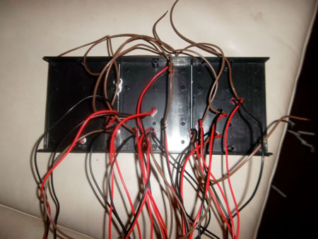
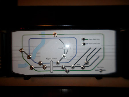
The other aspect of the point automation I thought was worth mentioning was the Mimic Panel. I made this out of a few electrical project boxes bolted together to form up a nice long panel. For the diagram I took inspiration from the London Underground maps. This type of graphic is really easy to read and looks good in colour.
The diagram was printed on paper and mounted on the face of the mimic panel under a sheet of clear acrylic/lexon.
Thats all for now. I will send through a post on the lighting next.
Cheers,
Cameron.
After the points were in place I decided that I wanted to light the layout.
A previous post, I think from Arnie, pointed me in the right direction with regards to how to control the lighting.
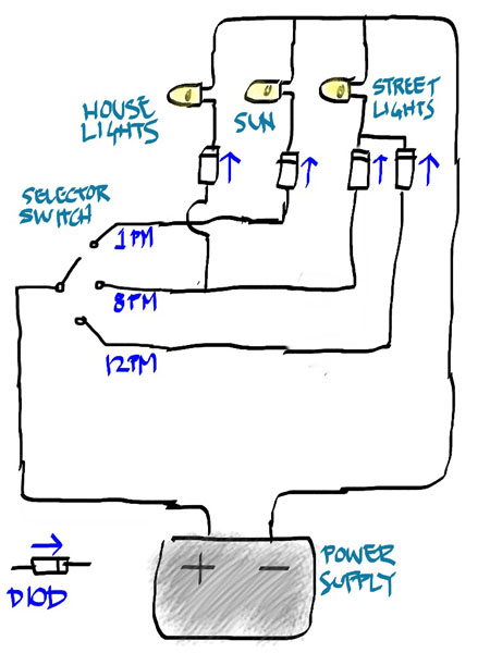
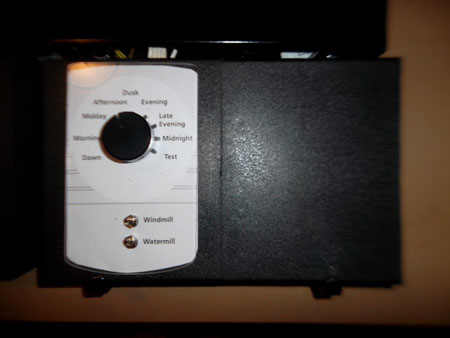
I wanted to have a lighting control dial that I could turn to different times of the day with each position of the dial turning on a different combination of lights. This is how I set it up.
Positioning the lights:
I fixed the lights in place from under the layout so I could take them out and change them without ripping up any of the buildings to do so.
I came up with this cheap fixing method that has worked pretty well.
I first drilled holes for each light before the buildings were fixed in place.
I then made a wire bracket from fencing wire (coat hanger wire would also be fine) that would hold the light in place but be fixed from under the table.
The below diagram and photo better describes this arrangement.
Cam”
Very smart! A big thank you to Cam for his model railroad turnouts piece – and for the lighting too.
That’s all for today folks.
Please do keep ’em coming.
And don’t forget, the Beginner’s Guide is here if you want to stop dreaming and start doing.
Best
Al
PS Latest ebay cheat sheet is here.




Cam
Ingenuity is what makes a lot of the fun part of this hobby. Some simple ideas make an installation great instead of just OK and there are some great tips you shared with us.
Big thanks to you & Big Al
Big Al
My tip for the day:
Even if you’re on the right track, you’ll get run over if you just sit there – Will Rogers.
Cameron reminded me that when I start wiring a layout, I always have the best intentions of keeping it neat and organized. The problems come into play when I get to about a thousand wires. No matter what my intentions were in the beginning, it always looked like a plate of spaghetti by this point.
It is quite possible and dare I say easy to thread a point motor up through the hole in the switch bar of a turnout/point from the top of the table. You need a small flashlight or light source and a way to grab the wire once it goes through the hole with one hand like a small pair of vise grips. Just look down through the hole and find the motor wire, follow it, and guide it to the hole in the turnout holding the light in one hand and the point motor in the other. once through the hole, hold it there, put down the light, and use the vise grips to grab the wire on top of the table. At that point, it will be easy to get under the table and attach to the motor. Rob McCrain
A very tidy mimic panel Cameron.
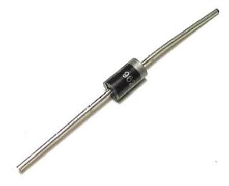
I particularly like the basic diode logic system used for the lighting control.
Ralph in Australia
Good one Cameron, I wish I’d thought of the toothpick method.
I must admit though that coming to the realisation that advancing years might make maintenance of the underside more difficult I probably have more lineside huts etc than prototypically correct! But working out cranks and rods above board created a lot of enjoyment too.
Was there a particular reason for using a straightforward power supply for the point motors rather than capacitor discharge? Certainly less complicated and no waiting for the capacitor to charge if a number of points need operating in quick succession.
David Priddle
Cam,
Very nice tutorial on how to align switch motors. Also love the lighting method. Please send photos or video of your various light settings when you get them finished.
looks like spaghetti, yum. just kidding, looks difficult but managable. nice job.
Like many of you, my wiring is a mess. It did not start that way, but as I have expanded my layout it has evolved into a spiders web of wires. My suggestions are as follows:
1. Make sure your bench work has pre-drilled holes to route wires through.
2. Strategically locate barrier bars under your layout to avoid having to run miles of bus lines to attach lights and accessories to.
3. Make sure you can access all areas of your layout, because you will inevitably move things around as your layout grows and you decide to move your dioramas around.
I just had to move my control board and am forced to rewire. It is a real chore. Accesories that worked before are now failing. HO scale wiring is so fragile that sometimes he slightest movement can break and disrupt connections.
Good luck to all and continue to have fun.
Dave