I got this tip in – I thought it brilliant. Anyone done it?
“Alastair,
Great ideas you send me. Here is one for the viewers.
If you are wiring a model railway and want to keep your wiring neat and tidy, use old Ethernet cables. There are 8 wires running through so you can wire points, controllers and other things – without your wiring looking a mess.
It works well if you have a Gaugemaster D controller – 2 x 2 for the Line A and B, then 2 out for the DC (for lights) and 2 out for the points = 8 lines out on the Ethernet cable.
Cheers
David”
Barry has very kindly sent in this expanded explanation of his wiring – and answered a stack of questions too! His original post is here.
Al.
“Hi Al, sending this email to explain some details on my test track.
I am running a Digitrax “Super Chief Extra” DCC system, which uses a protocol called “Loconet” to communicate to all the digital components.
The system comprises a “PS2012” – power supply, a “DCS 200” – command station, and a “DT 402” – throttle.
The PS2012 comes with a “YC52” Y cable, which has 2 x 5amp self-resetting current limiters built into the 2 cables (I am only using one leg of cable).
I have a “Powertech MP3097” – power supply to run all accessories which supplies 13.8v at 10amps constant. I use LM7812 voltage regulators to each of the Digitrax and accessory equipment, as this provides a constant 12v 1amp supply.
If anything draws more than 1amp, the LM7812 will cut off power, so it can act as a self setting circuit breaker as well. I did burn out 4 Digitrax DS64’s using power from the PS2012 (the other leg of the Y cable), but Digitrax has a no fault repair/replace 12 month warranty.
In answer to caw1, who was not sure of what he was looking at:
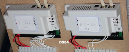
In the DS64 picture – it shows 2 Digitrax DS64’s, which control the switch/point turnouts.
The numbers 50 & 51 on the labels refer to their board ID address, and the numbers 101-104 & 105-108 is the address of each point/switch on the track, and as I am only using 3 points and a double slip, I am only using address 101 to 105.
The white wires going into the DS64’s, are the point/switch position indicators, as some software can use this feature to ensure correct turnout position – good for hidden or hard to reach areas.
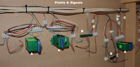
The Points & Signal picture shows;
A – the tortoise switch machines,
C – 6 core cable from tortoise NO & NC contacts for positive switch position,
D – fig. 8 flex (12v) supply from DS64 to tortoise (also note labels on cable, also on control board end as well),
B – Digitrax TSMK (Terminal Strip Mounting Kit) – which has a 10 screw terminal and current setting resistors for LED signals,
E – Digitrax SDCK (Signal Driver Cable Kit) – which consists of 10 core ribbon cable and 10 pin connectors.
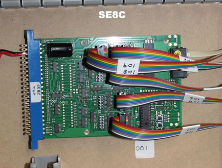
The SE8C picture – is a Digitrax SE8C signal decoder. This device is multifunctional, as it can also act as a turnout control, or occupancy detector. I am using it as a signal decoder, and the ribbon cables go to the TSMK’s in the previous picture. It can handle up to 32 signal heads.
The labels on the cable, are actual signal numbers, not the digital address, and the 001 number is the board ID (which I will have to change – as all Digitrax equipment have a default ID of 1, and it pays to have unique ID numbers. I have not change the SE8C ID, as this will also affect the signal address, the manual has diagrams for this feature, and is not hard to work out.
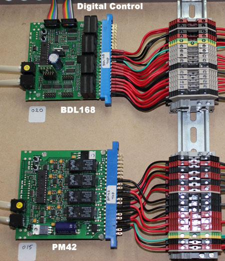
The Digital Control picture – is a Digitrax BDL168 (an occupancy detector), which also supplies power to the power districts/blocks on the layout and its ID# is 20. The 2 ribbon cables at the top, go to 2x(RX4) transponders, which will pick up the name of any loco/rolling stock the can transpond.
This can be useful if you are controlling your layout by computer (which I am), as it can display the name/ID of your loco’s/rolling stock wherever it is on the layout. I am not using this feature at the moment, as it is a Digitrax thing, and the decoders I have put in my other loco’s are SoundTraxx Tsunami’s. The PM42 supplies power to the BDL168 (ID# 15). As I only have 2 power districts on my test layout, not all output pins are used.
In the Red & Black terminals near the bottom, you can see 1 Red & 1 Black bridging link, these are the 2 track A & B power connections (the 3rd connection goes to power the SE8C module).
The output terminals (at the top) go to the BDL168 (except the very top – which feeds the SE8C).
The 4 Black rectangles (with white lettering), are 5amp (each) self setting circuit breakers, for when loco’s derail.
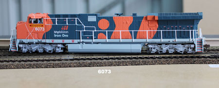
The last 2 pictures are of 2 of my loco’s that I am testing.
Loco 6073 is the reason I got back into MRR again, as I have actually been on this loco when I worked in one of BHP’s rail workshops in Port Hedland, Western Australia. I saw it on eBay one night while working interstate, and as it was well under $300AU, I bought it.
I then bought its sister (6072) from eBay as well, and decided I had better buy some track etc. etc. (most of you would know the rest), when do you stop.
These loco’s are Broadway Limited AC6000’s, come with DCC and 2 huge speakers in the fuel tanks, and they do sound rather impressive. I will send in a video later, when I can get a good external mic. for my Canon camera.
Paul Starr asked the question of wiring identification, I hope some of the pictures show what I have done.
Richard Moses mentioned track power soldering. I solder all my connections to the BOTTOM of the track, hidden by the ballast (which I do not have).
When I start my proper layout, I will solder the connections to rail joiners, which in turn will be soldered to 2 sections of flexi track (which will give me 1.8m/6′ lengths). I use solid core cable (not sure of size – it is small), which go thru table, then into terminal strips (which you can see in some of the pictures).
I also solder my points/switches the same way. I use Peco code 83 & 75 track, and Peco turnouts (points/switches).
Cameron asked about the ducts and rails. The duct is 25mmx25mm slotted (available thru electrical outlets or wholesalers), same as the “top hat” rail. Being an electrician (still working), I use these material all the time, and never thought about using anything else for my layout. I will go for a larger slotted duct when I start proper layout, as current duct will not carry all the cables.
Brian asked about where I got the realistic shrubs from, I am not sure if he had his tongue in cheek at the time, but it is a photo of a real steam engine travelling thru my back yard.
If anyone has any questions, please post below!
Regards,
Barry”
That’s all for today folks.
Please do keep ’em coming.
And if today is the day you get started on your layout, the Beginner’s Guide is here.
Best
Al
PS Latest ebay cheat sheet is here.
PPS More HO scale train layouts here if that’s your thing.



Thanks for the details very cool
Wish Barry could come and wire my layout , nice job you have done there , mine loks like an Indian Call Centre
I’ll tell you another wire that works good over the layout if you can get it. 25 pair or 50 pair telephone cable. That means you have 25 pairs of wires or 50 pair of wires. And they all have a different color wire. Got to get the glassess out to use on them LOL
I was reminded of an interesting experience, when I heard the live steam recording that finished Dave’s short video update. I used to play taped recordings of steam in action in my car. One day I was stopped at a pedestrian crossing enjoying the sounds when a train whistle blew and it thundered through the car from left to right. It was a hot day and I had the windows open – the reaction from the pedestrians (I han’t given it a thought!) was very amusing. One person even looked round in dismay and sort of ducked!
Ethernet cables might be neat but the wire isn’t big enough to carry the load. I think you’re asking for an electrical fire when you push that much amerage through those tiny wires.
Bill
This style and method of wiring is the way all wiring should be completed. However, to do wiring in this manner is costly. All well and good if you have the money to do things this way. Most of us get things running, one way or the other. The connectors and devices used in this demonstration are not cheap. It is nice to see that someone in the model railroad field has money and the time to do such a good job.
I envy you!
I wouldn’t know where to even begin to wire what you’ve done!
I am in the process of buying structure kits and making models, getting ready to create a running layout later, so I haven’t had to do anything electrical as yet.
It all looks complicated to me but by reading material such as this site,, books etc I plan to figure all this out.
Thank you very much for your information.
nice wireing job ,thank you for some ideas
Barry,
Thank you so much for your expanded explanation pertaining to the wiring of your setup. It was very helpful to me. I’m still trying to learn the lingo associated with model railroads. What is a tortoise switch? Is that a brand name? What is a double slip?
So much to learn, so little time to learn it!
Hi Barry. What a beautiful wiring job. I feel like giving up now when I look at mine. I find it hard to understand all the terminology used for the different pieces you’ve used as but a simple layman. I’m having enough trouble trying to get a Reversing Switch working on on my reversing track. As when the train gets to it on the return, it stops, then when the train is lightly touched, it begins to travel in reverse!
But on a lighter note, another marvelous clip by Dave. Thanks for the ideas!
What you do about building lights and street light that flicker?
I use cable clips to keep my wiring neat.
EXTRA GOOD LOOKING
My fiber-optic Christmas tree developed a noisy motor and the light got fouled up. I am going to try to remove the fiber optics from the tree and use it for lighting parts of my layout. I should be able to “wire” several houses and buildings with lamps in every room. I should be able to light multiple houses from just one LED.
Referring to a previous article on lighting a layout by time of day, I plan to light several living rooms from the 5:00 PM switch position, and their bedroom lights at the 9:00 PM position.
to me dcc seems to be a rich mans idea in between the chip and if required a sound chip then the special controllers not to mention what looks like the control panel at Nasa
am I wrong I no longer go to my club because ive still have the old style of trains and the club have switched to total dcc.
Can Barry come over to my place Al, I have so many wires going here and there, hanging under my table everywhere. Thanks for sharing this. Love my DCC layout and huge rail yard. Al, I should you some pictures. Have a great day everyone.
I see that there is still an interest in standard D.C. layouts, good to see.
For “Carl in Kansas” and others who plan to use Fiber Optics for lighting.
1) Be aware that good Fiber Optic material is NOT cheap and is made of either high grade plastic or real glass strands. They DO expand and contract due to changes in temperature, and they can be broken.
2) You will lose light intensity thru the sides of uncovered fibers.
3) You will need at least four to eight fiber strands for street lights to be bright enough and many more to light up a “HO” scaled room, let alone in other scales.
4) When you are routing your fiber strands, be sure to provide extra length when going around curves and corners, and not to do a sharp bend when feeding the fiber thru your layout base. Light does not make it around sharp corners or thru broken fibers very well. My rule of thumb is “add an extra inch or two for ANY bend, turn, twist, corner or feed thru”.
5) When you bundle your fiber strands together, using heat-shrink tubing works very well but remember that TOO much heat can damage the fibers by melting them together, or causing them to break. Best to route the fiber bundles with unshrunk, heat-shrink tubing the way you want, then gently heat the heat shrink tubing.
There you have it for Fiber Optic material.
The electrical connectors need not be expensive since large amounts of comms and data equipment is thrown out each year when business upgrades. Just check out the dumpsters near renovated office blocks and you will find sockets, plugs and other useful electrical bits.
Cheers
Ralph
Love the neatness. to me that is so important to have all your wires inorder. clean work good job.
neat wiring you took the fun out of chasing wiring faults.great tips. Dave is there a way of getting all your stages of your new layout in a bundle. Ian australia.
Excellent wiring job and a great description of the photos.
I run a Digitrax system too. One thing that impresses me…. I ran a Loconet line to my home computer, where it is connected to a PR3 Digitrax command control, which in turn is connected to my computer with a USB cable. I downloaded Panelpro to my computer and WiiThrottle to my iPhone. Alas, I can choose any two engines and run them from my phone.
Great wiring, nice and tidy. Great tips again. Keep them coming.
Willie, Scotland
Reply to Dave. Love the videos. I heard you mention on update No7 that your trains stopped if your Dynamis was not pointing in the right direction, because of the timeout feature. It is not very prominent in the instructions but you can turn this feature off so that you can put the handset down without having it constantly pointing at the base unit. Here is how to do it:- Push the menu button once, you get edit name 0003. Push the paddle to the left once, you get System menu. Push the tick (yes) button once, you get Edit base ID. Push the paddle to the left twice, you get Edit TRK timeout 30 sek timeout. Push the tick button once, the 30 sek flashes. Push the paddle left 3 times, you get No Timeout flashing. Push the tick button once. The screen should now go back to start up. You may now put your handset down in any position and your trains will keep going, but you still need to point your handset at the base unit to make any control changes. Hope this is of help to Dave and anyone else who uses a Dynamis system and was not aware of this feature.
Mac, North Devon.
Dave,
Love your layout! Could you advise me? The model buses I spotted have the livery of the old Halifax bus company. Am I right as I left Halifax in 1962 for the warming climes of Gloucestershire. They had a bus station next to the old Shay football ground.
Please reply as, although my memory is fading, I think I am right on ths one.
Ian Leech
Barry, want to come to my house and wire my layout ? Being new at this model railroading , Man, it looks like you have to be an electrical expert……….scary.
I am having trouble wiring the lights in my roundhouse, there is nine sections with three lights to each section. There is a new neutral and hot wire but when I hook up it lights only one section but not the other 8 sections of 3 lights.
Just watched Dave’s latest video. Where does he buy the points motors he mentions please.
Regards.
Roger in France
I have been an electrician for over 40 years & this looks to complicated for a novice & even myself. I like to keep things a simple as possible. My motto for my old set was 2 wires for every item, hot & ground, we call this KISS,(keep it simple stupid)
I love the wiring but many of us are too old, not electricans, not deep enough pockets and still like the old fashion DC. Many of us are on social security and just love the hobby. I love seeing all you high tec guys stuff, but I do it as HOBBY. I like the guys KISS Tom in AZ By the way what is the meaning of a POINT?
I was thinking about current limits on small wire also! I have old serial and parallel cable from EARLY computer systems (25 larger flex wires each colour coded & stronger insulation and shielded.) 25 pin D shell plugs & sockets to fit!
I am planning DC only also! Cab Control ( if I find the OLD books and have the time) – simulated inertia as well! (throttle and break on the main line controller).
Do switch motors have power to them constantly? If so, about how much? I’m curios and wonder if a dozen switches would have a significant current draw?
The sharing of ideas on this site are just fantastic providing tips and info not readily available to everyone from other sources.I am trying to get started in this hobby but confess that i am being overwhelmed by all this technology,especially wiring and controls.I have a legacy control system that i am still trying to figure out and to complicate things I have k-line super-snap track track.I still haven’t been able to figure out the best way to wire Many of us do not yet have a good grasp of the fundamentals and hence are not able to expand our skills and get stuff operational.After going thru this well done but technical article I realize that i have a lot to learn.Sometimes it seems overwhelming to the point where i just quit.These articles may be helpful to the more experienced modeler and are very much worthwhile in that sense,But for us novices ….?I can’t speak for many but i suspect articles that help explain to us in understandable terms the basics would be quite helpful ,as well help us graduate into higher levels of understanding.IN any event keep up the good work and please keep us novices in mind.Thankyou
I am attempting something similar with regards the Digitrax setup. Any chance you would have a wiring diagram of the connections between the PM42, BDL168, RX4’s and the SE8C? The Digitrax manuals are a little vague when it comes to actually wiring things together. What size wire did you use for the BDL168/PM42 connections. I too am an electrician and have access to duct and terminal blocks and yours is the neatest example of wiring I have seen so far.
Thanks in anticipation
Barry, how does your Digitrax wiring setup diagram of the connections between the PM42, BDL168, RX4’s and the SE8C compare to modeler’s like me when we use the NCE DCC System? I’m still building my 7 X 11 Layout with my track and wiring will be next… I’m retired at 76 and I too in my early years worked as a Electrician, Telephone Company and Wiring Tech for Industrial Motor Control… I’m looking forward to wiring my layout.
Great wiring information Barry and thanks for sharing.
John Gomez, Fort Lauderdale, Florida USA
I use 4 wire telephone wire and mark them. You can buy it very cheep. I was building a 40 x 60 foot layout but changed it to a 60 x 60 foot when we started laying blocks.
Your wiring job is top notch,as a system engineer for AT&T and the Bell system for 32 years, I have always used telcom cross connect wire for ligts and switches,
20 gauge has worked great for me and no problems
Hi, I have none of these issues – all my points/switches are manual
Andrew in Oz
Al,
You recently noted that some readers can’t access your blog when they click on your regular access url. I had the same problem, until I tried Ctrl + “Enter.” Why does it work? Beats me.
George
Toni writes: 2) You will lose light intensity thru the sides of uncovered glass fibers. Not true. The problem once existed perhaps four decades ago in what was called “multimode” glass fiber. But todays fibers, called “single mode,” are designed to keep the photos (light) on a very straight line within the glass fiber by a process called “refraction” (think “reflection.)” The outside plastic coating is there to keep the fiber from being scratched or easily broken. Ah, this is probably more than you care to know.
To Tom in AZ: A “POINT” to the Europeans is the same as an American turnout or switch. A piece of track that allows the train to take either of two paths. In the US, the points are the tapered rails that move to conect the path to either the main or branch track path.
To Donald Kadunc: The switch motors only have momentary contact to the power source, so there is not a continuous power draw from the motors. Someone else asked what a Tortoise is: Tortoise is a particular (very popular) brand of under-table mounted switch machine.
Barry, Thank you for the detailed explanation of your DigiTrax system components and wiring. Though I’m an old model railroader, that looks like a lot more work than I’m prepared to undertake for my little Christmas layout. I am impressed by your grasp of the DCC/Digitrax components and how to wire them. Keep up the great work — is gives us mere mortals something to strive for.
Alastair, I just want to thank you for this super informative blog.
I am 82 years old, and just starting my first layout. I enjoyed model railroading with my Dad as a teenager, but have done nothing since. I retired 14 years ago, and went back to work a couple of times out of boredom. lately, when this pandemic hit us, someone said to me “you need a hobby”, and thinking about my younger days, I started this layout.
The hobby has changed so much since the big names were only Varney, Atlas, and Mantua kits. Plaster cloth and the use of foam replacing the old “mountain paper”, high tech electronics with DCC and fiber optics, and the beautiful locomotives and rolling stock.
I have secured one half of my garage for a 4’x10′ HO layout. May prove to be a mistake because of our high heat and humidity, and no air conditioning. If we have a hurricane or tropical storm, my car will have to find it’s own shelter!
I was going to try N gauge, but age told me I couldn’t handle it. I went with all Kato track as it was the easiest. The track has been my most expensive part, while everything else has been given to me or bought used on Ebay.
I am not to “artsy” when it comes to the mountains and scenery, but watching many videos, and constantly learning so much. My layout is currently flat and uninteresting, but I will come up with something to make it interesting. I just wanted to get the track down to see what could be done in 4×10 area. I am not experienced enough to be the prototypical type, so I am just “winging it” with ideas as I go along. I have already made a few big mistakes, but will overcome those. I have also tried a couple of your print-out structures, but not sure if I printed and built them to the right scale. They look kind of small.
My point is, the contributors to this site have been invaluable to my learning process, and I read it every day. My earlier days were always job oriented raising a family, and now I am having fun again. Thank you all, and keep up the great suggestions.
Don – South Florida
Hi to all. and especially Al:
Fairly new the the chat. All of your hobby ideas are just great! The wiring expose under Barrys’ layout is a lot like mine. To make it look easy and say it plain, most jobs like Barrys’ are either from electricians or phone techs. I was the latter. I do have to ask Barry what type of wire comb he uses for his wire looms.
To all, keep up your great work and have lots of fun.
Bud
That’s genius. The wiring is something I don’t know a whole lot about. I’m recently retired and have admired model railroading since I was a kid. I’m 57 and have learned a lot on this site. How can I start out with simple wiring instructions and add to it later if that’s even possible
well done at this rate we will be electrical engineers
Ethernet cables and ribbon wire are only meant to be used for “signal” level voltages and currents. Ethernet should not be used over 24v and 1 amp current without unacceptable heating. Most are 24 gauge or smaller. Ribbon wire is available in larger gauges, but to get decent current capability, you should go 18 gauge or less for any long runs, and that stuff’s expensive.
LED’s use so little power that both kinds are fine to use, and they’re also great for “sense” wiring (i.e. a magnetic switch or a turnout position indicator as long as it is still low current.
I will be using ethernet cables to remote distribution and sensor boards where I can multiplex dozens of circuits onto one ethernet connection. RThe boards and software for both are still under development, but I will be able to send over 100 sense points back to the computer over one ethernet connection.
The controller looks like it will be limited to 16 switch ports in the fitrst iteration.
Plans for both systems will be posted as soon as I kill all the BIG bugs!
Charlie