Michaels been in touch – he’s built his N scale on an old door.
“Hi Al –
Thanks for sharing your regular stories & photos.
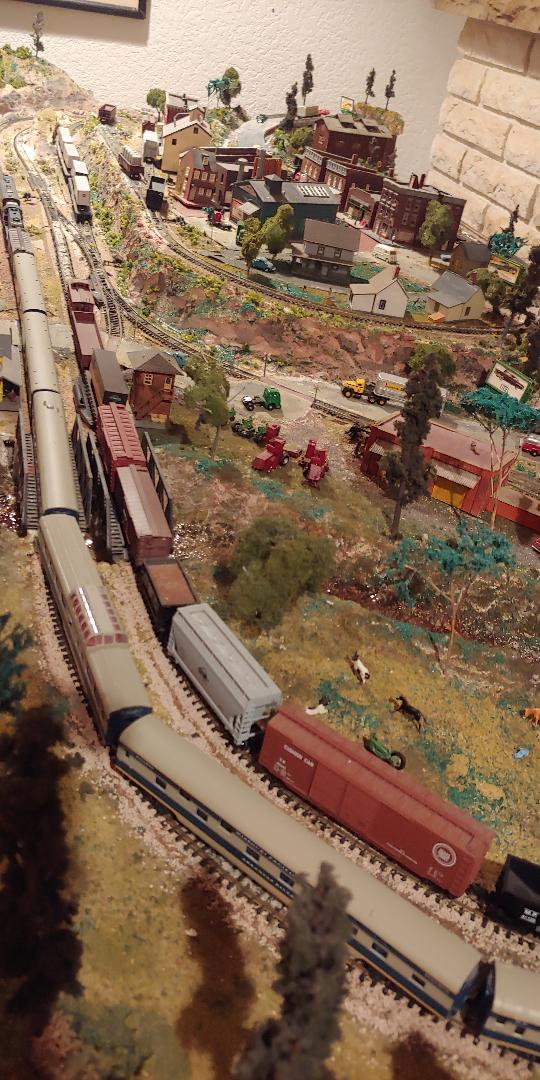
Here’s a photo series on my N-scale layout, built on a hollow core door.
It’s now in it’s third location as we’ve moved through the years. My main modeling interest is HO and Lionel O, but the ability to work in a tight space with smooth running equipment makes this N gauge system a different experience.
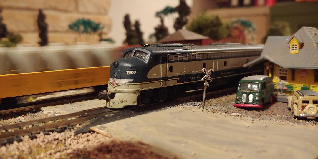
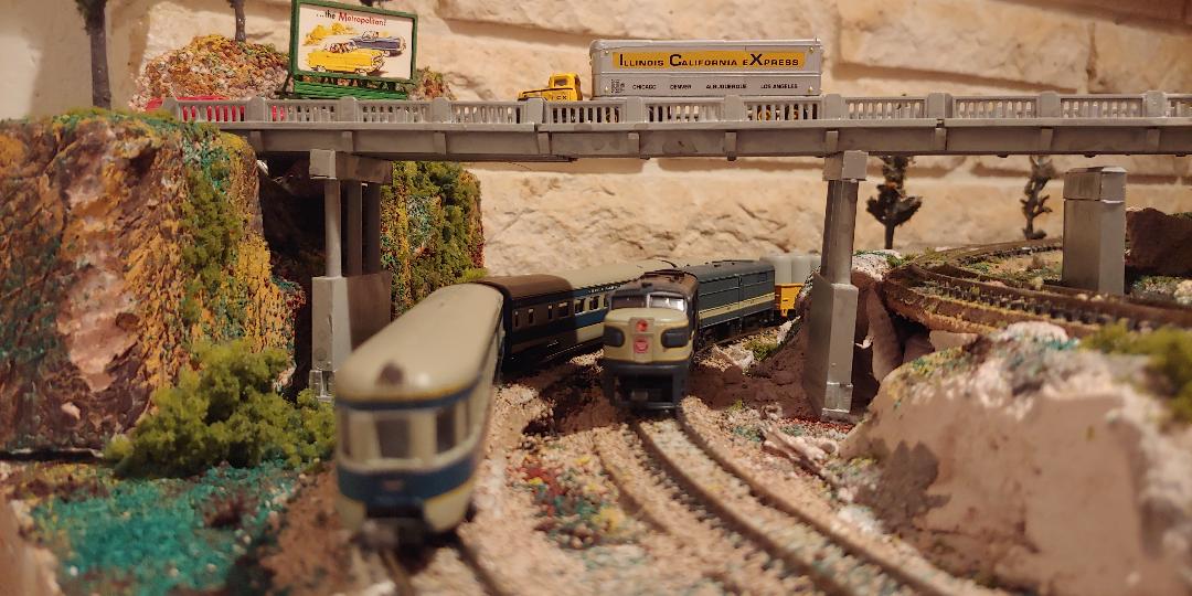
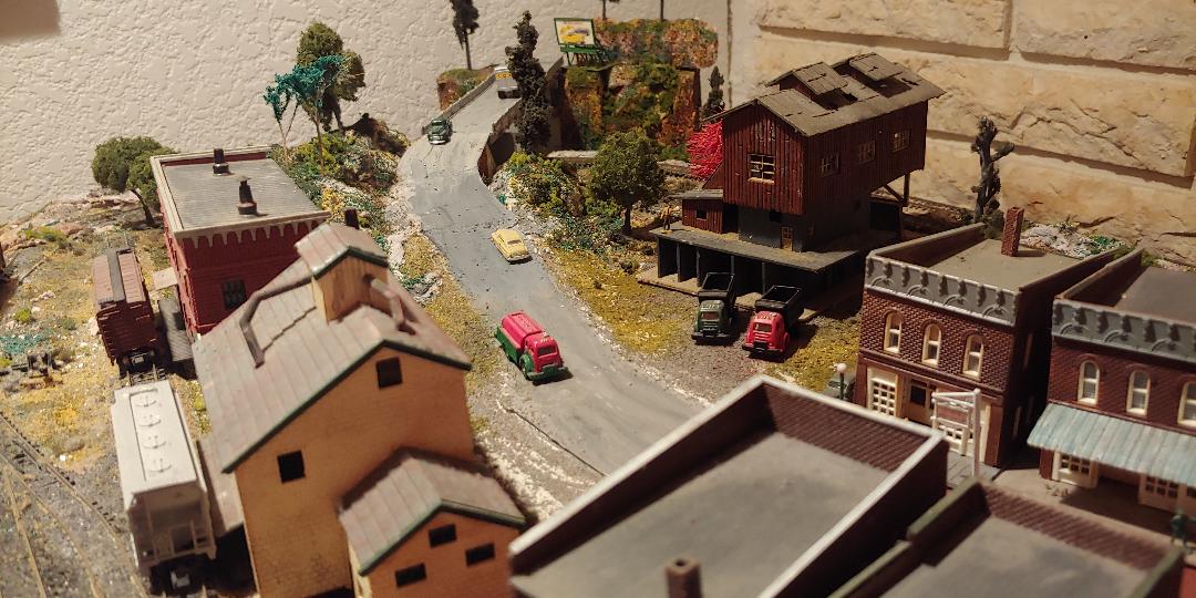
Because of the hollow core door, I was able to “pop up” the town in the center and also include a waterway, without elaborate scenery construction.
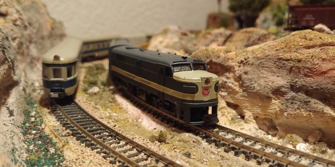
The setting is a typical Missouri small town on the Missouri Pacific Railroad. My first train ride was when I was about five, on the “Missouri River Eagle.” Growing up in St Louis, the MoPac was a constant presence, along with the other lines that intersected there.
Their original cerulean blue and gray paint scheme was very eye catching.
My Dad and I used to take a four block walk on summer evenings just to watch the “Texas Eagle” pass through our neighborhood, beginning its long journey southward.
I remember Alco PA locomotives hauling a long consist of coaches, sleepers and a diner.
A small crowd would gather in the evening, just to watch this majestic train pass.
The locomotives are LifeLike, the passenger cars ConCar and an assortment of Kadee and Atlas freight cars.
thanks for sharing
Mike
Normal IL USA”
“Hi Al
Thanks for the emails.
I am not new to n scale model railroading, my father introduced n scale to Australia in 1962 and modelled European until 1975 when I moved from O scale to N Scale and together we built an extensive layout used for exhibitions over last 40 years.
I model Canadian Prototype the post-war years to modern-day around the Great Lakes.
Dad modelled Nth America NYC/B&O along with his own label T&S (Tiers & Stramish) – this allowed him to freelance with anything and Sister joined us in Mid 1980’s modelling Soo Line & B&O & Chessie System.
Dad passed away at Easter and have been going it alone ever since having inherited his entire collection including layout rolling stock books etc. I am involved in LaTrobe Model Railway Club in Gippsland Victoria and also Warragul Train Shed and Drouin Men’s Shed where there are 00 British Layouts.
I am currently building my home layout from scratch incorporating parts of the exhibition layout that have survived. The layout is based on Modrail which was developed by Dad and a Retired Royal Engineer Gordon Duncan for N scale and HO Scale.
My tip is for Ballast use builders sand (Don’t ever use Beach Sand due to salt content) dry it out in the oven on a baking tray when the wife is not looking. The higher the heat the darker the ballast will be. You can then apply as Woodlands Scenics method and its a lot cheaper particularly if you have a large area to ballast. You can also colour the sand using powdered paints.
My second tip is to collect silver birch branches and twigs they make good timber loads for flat cars and work well if you are (pouring a resin) river/lake/waterway and want to have some logs floating or submerged in it.
Regards
Don”
A big thanks to Don and Mike.
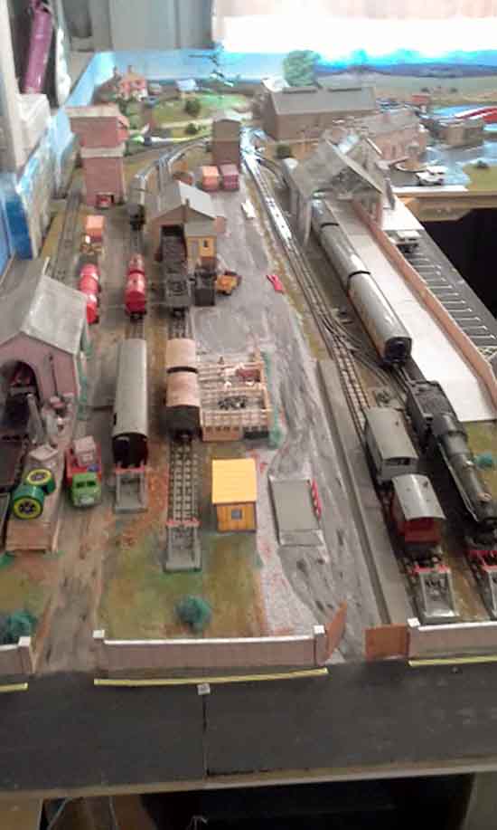
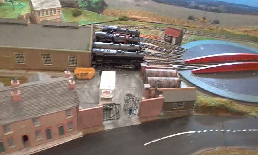
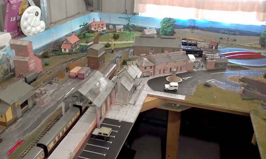
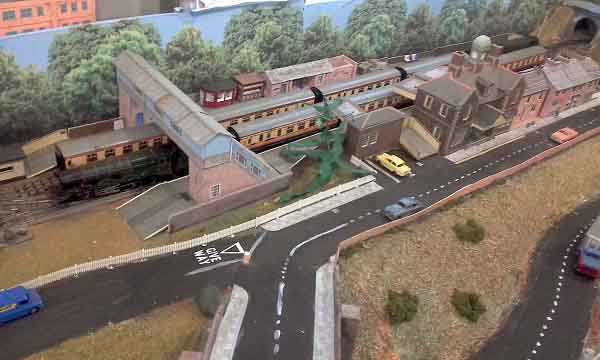
I thought Mike’s pics were fab – so much packed in to a small space without looking cramped.
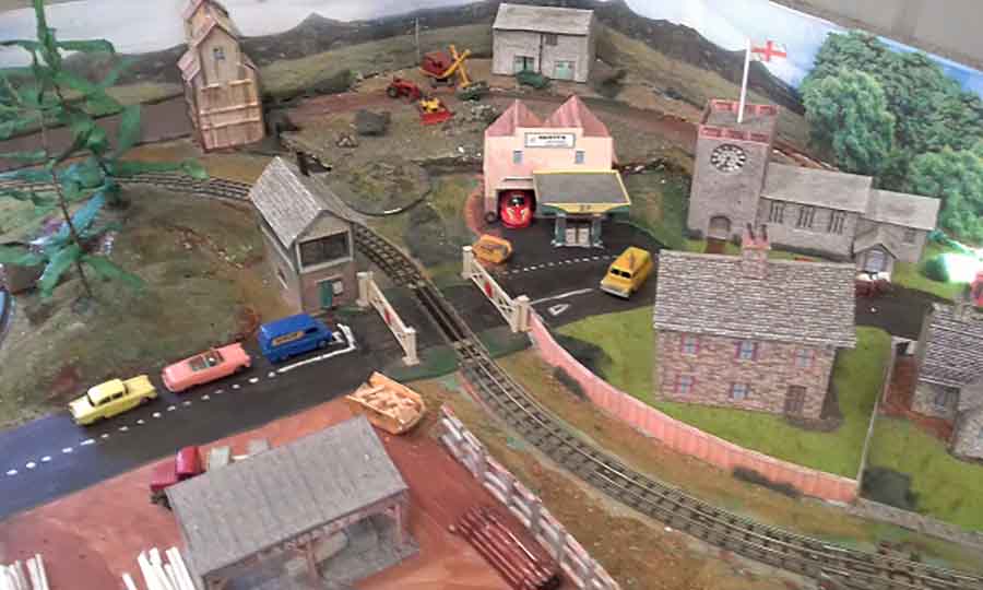
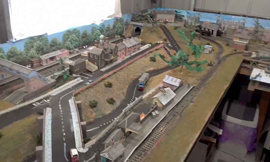
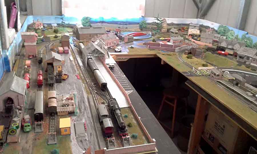
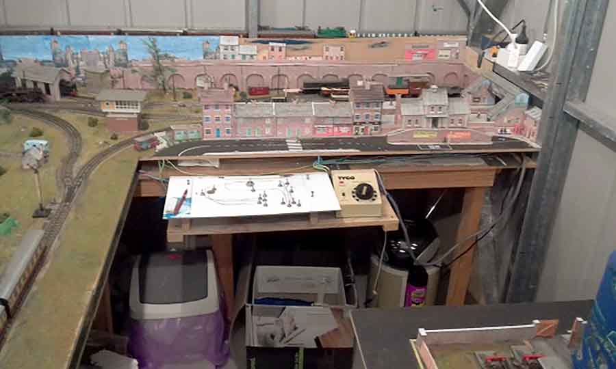
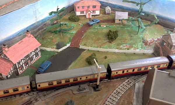
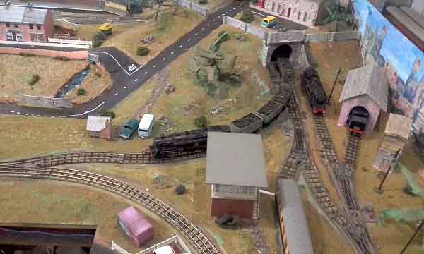
Andrew’s been in touch with his Hornby Dublo layout:
“G’day Al from ‘Down Under’
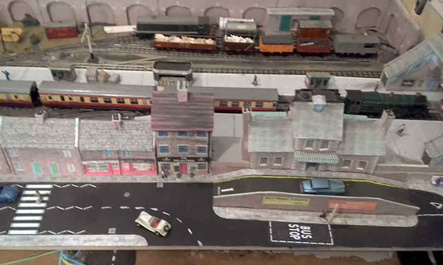
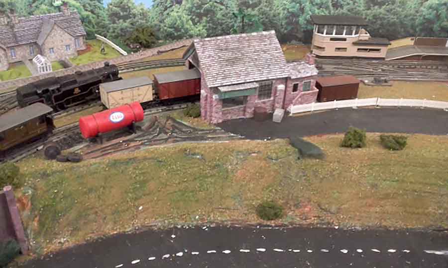
I am delighted that you are continuing to run your magnificent blog, so many ideas to try and I now have several of your buildings on the layout. The Tudor House is my favorite.
Two years ago I was fortunate to get an opportunity to purchase more Hornby Dublo 3 rail track, locomotives and rolling stock from a new friend here in Oz.
His, like mine is 60 to 65 years old and in working order. and this enabled me to enlarge and rebuild my layout, a task that has given me many hours of enjoyment and it is fully operational.
Unfortunately I do not have the equipment and skills to send a video so attached are photos of my layout Mark 2.
Now it is finished (??) I am ready to dismantle and start again and to try some of the new ideas I have from your contributors.
Thanks for all you do.
Andrew
Cooroy, Queensland, Australia”
A big thanks to Andew for sharing his Hornby Dublo.
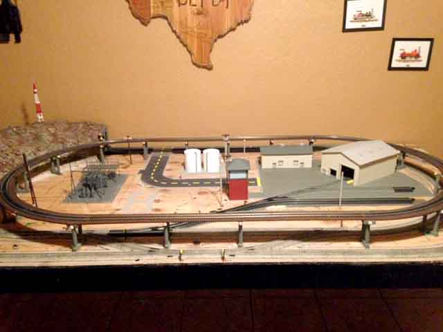
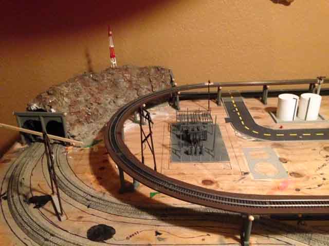
Now on to Jose.
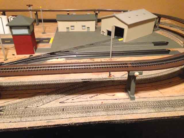
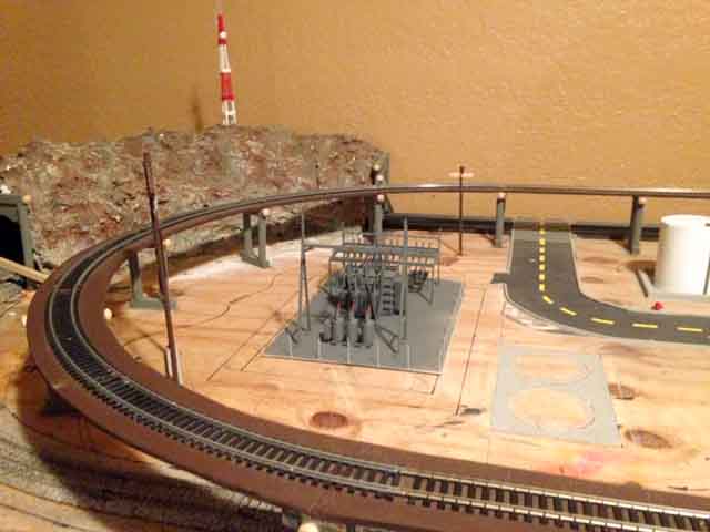
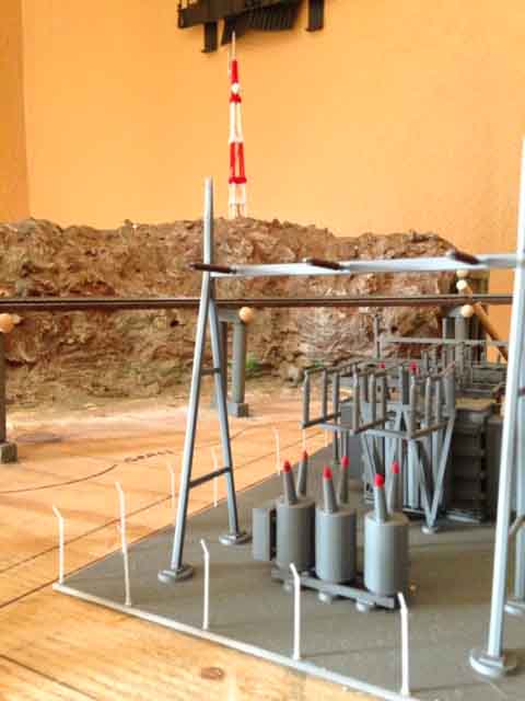
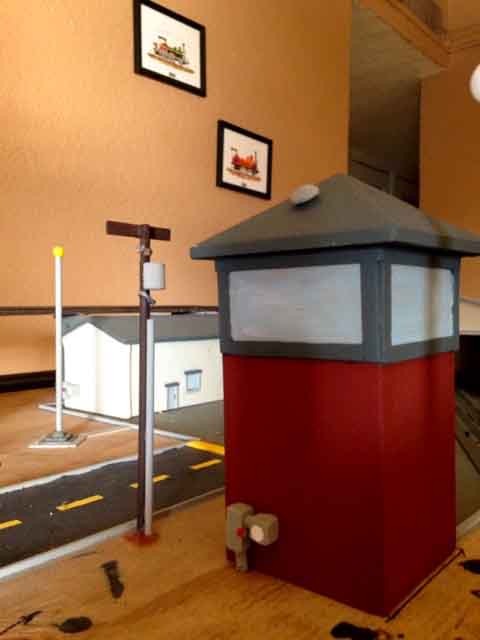
“Wanted to share my HO layout that I have been working on. I built everything by hand, except the track and electrical power station.
Jose”
Jose has made that all important start – and that’s what this hobby is all about.
Andrew’s been in touch with an excellent ‘how to’ on model railroad signal design:
“Hi Al
Firstly, I must compliment you on a stunning site full of the most useful tips and instructables.
But I don’t want to be a taker and not offer something in return, however, modern technology and I don’t always sit comfortably around the same table so I am unsure as to how to submit my little offering.
Living in South Africa with a most unfavourable exchange rate makes the railway hobby more challenging than it is for our counterparts in Europe or the Americas so necessity becomes the mother of invention and we have to find affordable alternatives.
So being old school and not following the DCC trend, my objective has been to develop cheaper methods to achieve similar ends within affordable limits.
We tend to spend our money on mostly locomotives because that is what gets our hearts pounding and then we scrimp on the accessories regarding them as being very expensive for what we get.
Yet we are surrounded by sources of low cost items that can be easily converted to reasonable facsimiles with a bit of effort and very little expense.
A great source of components is old/broken CD/DVD drives which many computer shops are willing to give away at no charge. Strip them down and here are some of my offerings for model railroad signal design :
2 ASPECT LIGHT SIGNAL
From the main board there is (sometimes) a duel LED holder, normally both green but simple to remove and replace one or both with either red or amber LEDs. Then with the purchase of a few other items, follow these steps:
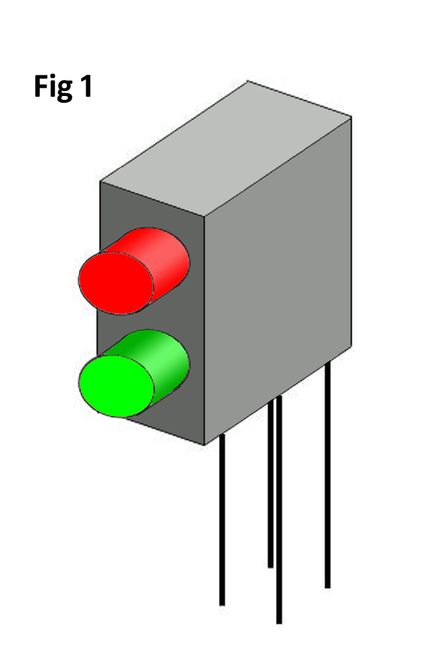
If you have purchased the items rather than strip down the DVD drive, the item in figure 1 is available off the shelf with a red and a green LED.
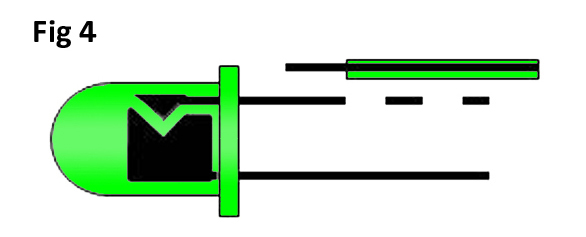
Start by carefully bending the legs of the LED up so that they point straight out the back of the plastic holder as indicated in figure 2 and then gently ease the LED’s out of the
holder.
Increase the size of two of the diagonally opposite holes as indicated in figure 3 with a 1.5mm diameter drill being careful not to drill into your fingers.
The purpose of this is to accommodate the thickness of the wires to be used and I use one of the pairs of wires from inside a CAT5 network cable which is readily available in suitable lengths.
Un-twist approximately 25mm of the pair and push each one through the enlarged holes. You may wish to strip off about 3mm of insulation on each one and tin it first. Put it one side and now on each of the LED’s, trim the anode leg (the longer one) down to approximately 3mm and tin it using flux. With a light touch, solder one wire to the anode of each led.
Be careful not to apply the soldering iron for too long as this will cause the insulation to melt away with the risk of a short. The use of flux here will allow the bonding to occur quickly.
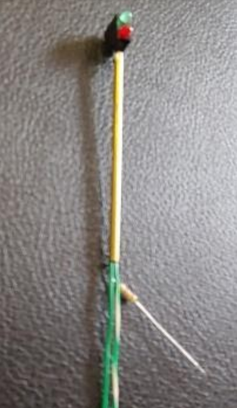
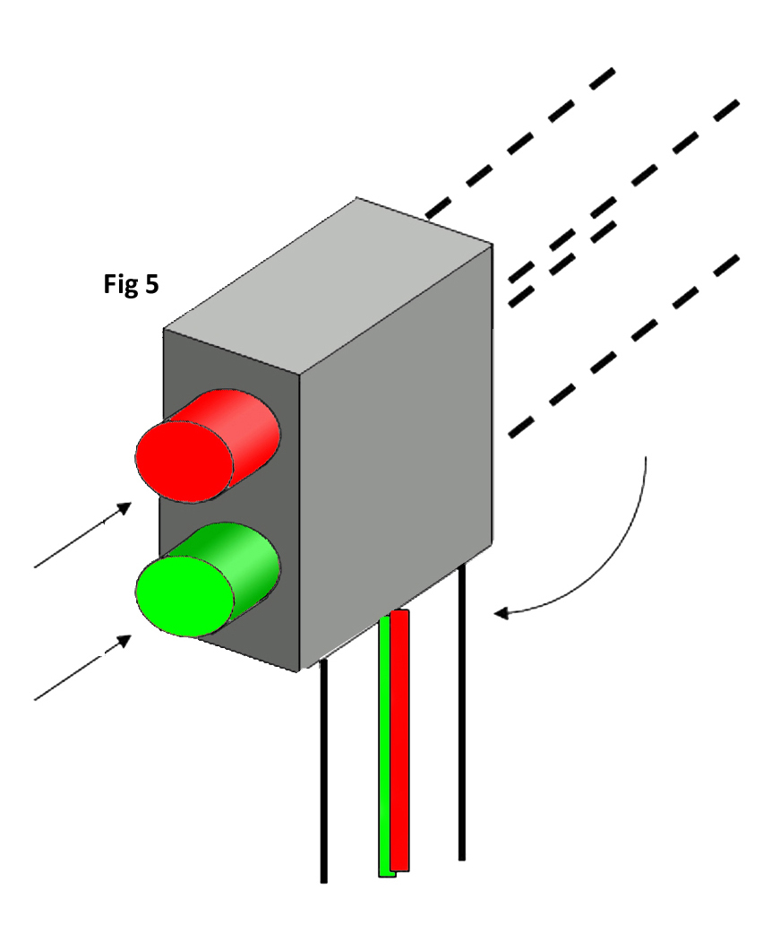
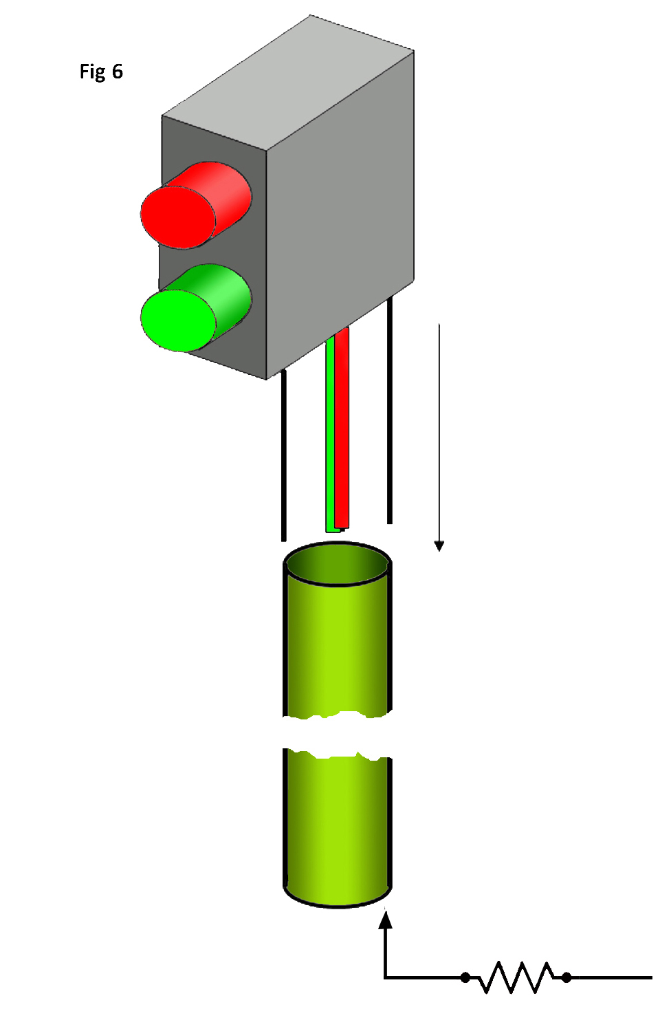
Re-insert the LED’s into the holder through the original holes and carefully bend the wires from the LED back to their original positions as indicated in figure 5. Cut a piece of 2.5mm diameter brass tube to ±90mm long and using a drill bit.
Remove any burrs from where the tube was cut……you don’t want to nick the insulated wires after the previous effort.
Thread the 2 wires down the inside of the tube.
Cut the 2 remaining LED contact so that the project beyond the holder by approximately 3mm. Bend the two LED contacts so that they fit snugly on each side of the brass tube and once the LED holder is positioned “on top” of the pole in the desired position, solder these 2 legs onto the top of the pole.
All you need now is a ±800Ω resister to be soldered to the inside of the tube base, a touch of paint and voila!
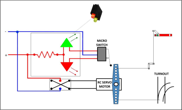
For a suitable circuit diagram, please see below where an RC helicopter servo motor can be used. For the purpose of this topic, I have displayed both the LED 2 aspect signal and a semaphore signal. The micro switch is another component “rescued” from that broken DVD player.
In the above circuit diagram, a servo motor is used as the point motor and is reasonably inexpensive from eBay coming in at around R30.00 apiece. In order to obtain the functionality, the circuit board inside the motor is removed and the two wires from the motor are connected directly to the DPDT switch (Make sure the switch is a centre-off, non-latching type). The micro switch from the DVD drive is a 3-pin type which is spring-loaded centre-off.
In the event that a manual semaphore signal is to be activated, this is connected to the arm of the Servo motor by means of a stiff wire (piano or spring steel) and then via the crank, can activate the semaphore signal.
The servo motor is mounted directly below the turnout with a stiff wire fixed vertically through a hole in the base board to the centre of the turnout draw bar.
COMPONENTS & PRICE
Admittedly, the electronic components below have been sourced at one outlet only and you may have a preferred supplier or even other items that you can strip for components. Feel free to modify the circuit diagram if you want to adapt the circuit for your specific model railroad signal design.
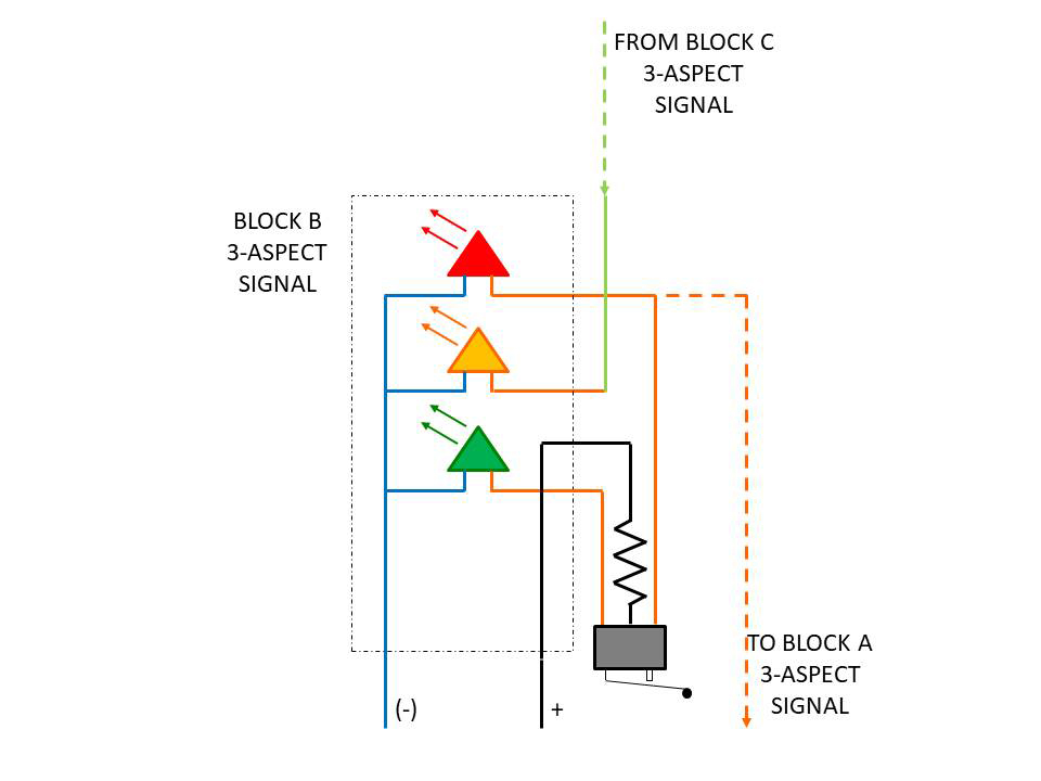
For example, you may wish to install a 3- aspect signal and for this you would need to modify the LED header as they are only available in combinations of 1, 2 or 4 LEDs. The easiest would be to purchase the 4-LED header (part no L-934SB/4SRD) and cut away the top LED position. No big deal as you will score an LED for future use.
Also, the sub-micro switch configuration would have to change and maybe the installation of 2 SPDT type switches will do the job (I will figure it out and revise the circuit diagram).
Of course, you don’t need to install the servo motor system and if you are using manual or built in turnout control, it would mean that you would have to position the sub-micro switches a little differently, maybe on top of the baseboard and then hide them behind other scenic items.
At the end of the day, considering that to purchase a turnout motor and a multi aspect signal could cost you well over $25.00, this provides you with the means to produce the same for just $5.00 with the added advantage that you could connect multiple 2 or 3 aspect signals to the circuit.
Here is my circuit diagram to simulate block occupancy where the “trigger” could any one of a number of methods depending on your preference. I have illustrated it using the micro switch method illustrated above.
Thank you once again for your superb contribution to the hobby and may it continue for years to come.
Kind regards
Andrew”
And now on to Hall of Fame member, Rob:
“I have purchased many signal heads and thought I could build my own for about 1 tenth the price I have been buying them.
I tried it and it worked so then I thought building one with the camera running might interest others.
A huge thanks to Rob and to Andrew for sharing his model railroad signal design- if you’ve ever thought of cobbling together your own signals, I hope today’s post has helped.