Cameron has very kindly done a points and motors ‘how to’ after spotting so many questions on the subject in the posts.
Thank you Cam – and can’t wait to see more pics / video of your layout.
“Dear Al,
It’s been a while since my last post.
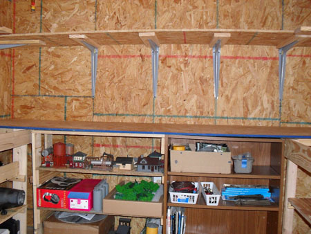
I have spent a lot of time over the last couple of months lying under the layout with wire cutters in one hand and a soldering iron in the other. There is now a big mess of wires under table that reflect a lack of planning on my part. I bit embarrassing but part of the process.
Following is a couple of tips on electrifying points on a layout that might be of use to a few of your readers.
Points and Motors
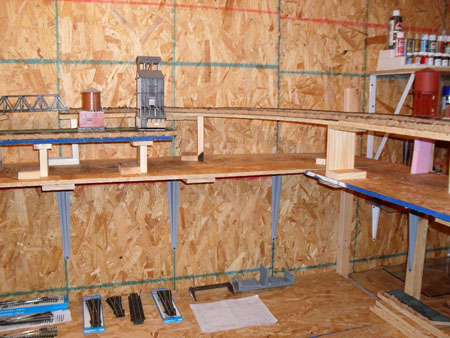
Before I laid the track I drilled holes in the right locations for the point switch rods. I would do this again regardless of whether I planed to electrify the points or not. You never know how hooked you are going to get on this hobby.
I used Peco point motors which have been quite good. Rather than using the propriety plastic adapters I simply bent out the fixing prongs to act as a fixing lug. Perhaps a bit rough but a lot of modelers seem to use this method.
They all run off a 4amp 14v power supply which is not at the top end for this type of point but has been reliable.
Lining up the point motors under the track for reliable operation is one of the more difficult parts of the process. I did however find a pretty good process worth sharing.
1. I drilled two small holes through the top of the layout at each end of the plastic switch operating slide. These holes have two purposes. They provide a reliable guide marker under the table and, if drilled at the right spacing can be used to screw the point motor in place from under the table.
2. I set the point in the central position and held it in place with two tooth picks.
3. Working now from under the layout I lined up the motor so that the motor pin was in the middle ( evenly spaced) from each motor magnet.
4. The motors were screwed in place with a couple of screws and washers.
5. Remove the tooth picks and you should have a well aligned motor.
For me this method took a lot of the guess work out of the process of positioning the motor and ensured a lot less adjustment was needed to get them all working.
The other aspect of the point automation I thought was worth mentioning was the Mimic Panel. I made this out of a few electrical project boxes bolted together to form up a nice long panel. For the diagram I took inspiration from the London Underground maps. This type of graphic is really easy to read and looks good in colour.
The diagram was printed on paper and mounted on the face of the mimic panel under a sheet of clear acrylic/lexon.
Thats all for now. I will send through a post on the lighting next.
Cheers,
Cameron.


A big thanks to Cam – nicely explained.
That’s all for today folks.
Please don’t forget the Beginner’s Guide is here if you want to stop dreaming and start doing.
Best
Al
PS Latest ebay cheat sheet is here.


")


