Frank’s been in touch with a fine piece on how to power turnouts on a model railroad.
He’s solved two of his problems – but can you help with the third?
“Hello Alaster, Frank from Surrey, BC here again . . and I think I'm going bald!
Being in Canada, I get to wake up with your emails waiting for me and they are the first I open every day. Thank you again Al.
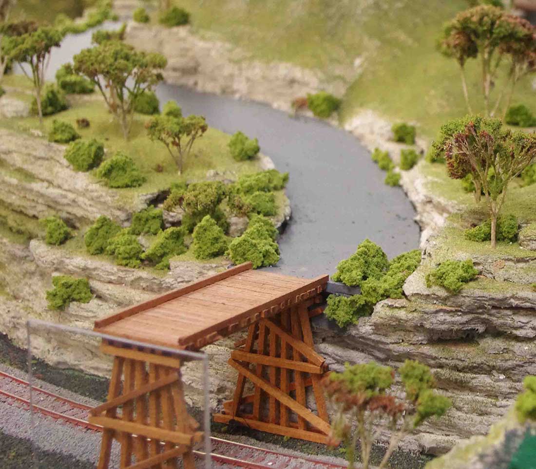
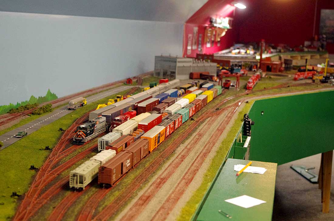
I read your daily posts with a combination of delight, envy and frustration. Delight at seeing the beauty others have created; envy at wishing I had their talents and frustration thinking that "I'll never get to that level of excellence."
Then I remember the real reason for doing all this is to have fun!
In one of your recent posts, Richard made an excellent point that I seem to have ignored, possibly at my peril.
He said, "Regardless as to how big you eventually "grow" your layout, don't make the mistake of trying to do everything at once."
Those are truly pearls of wisdom. I realize that my D&L is a BIG project and truth be told, there are times that I feel overwhelmed by it's scope, but, I have put a lot of time an money into it, so, as they (who are "they"??) say, "I will persevere".
I would add that he made several other EXCELLENT points. Obviously, a very wise man.
So, one issue with building a railway in an unheated area in the Canadian West Coast "winter" is that . . . . well . . . you can't! So, to wile away the chilly time (it's not really that cold at home), I worked on a few electronic projects.
Two of the projects are a main power supply for the DCC equipment and another to operate Kato, PICO and Tomix turnouts using push buttons.
Both Kato and Tomix us only two wires to operate their turnouts, the polarity of which determines whether the turnout is set straight or bent. For the Kato turnouts, I had planned to use two 12 VDC power supplies to get +12 VDC and -12 VDC which would be send to the coil with push buttons. NO PROBLEM.
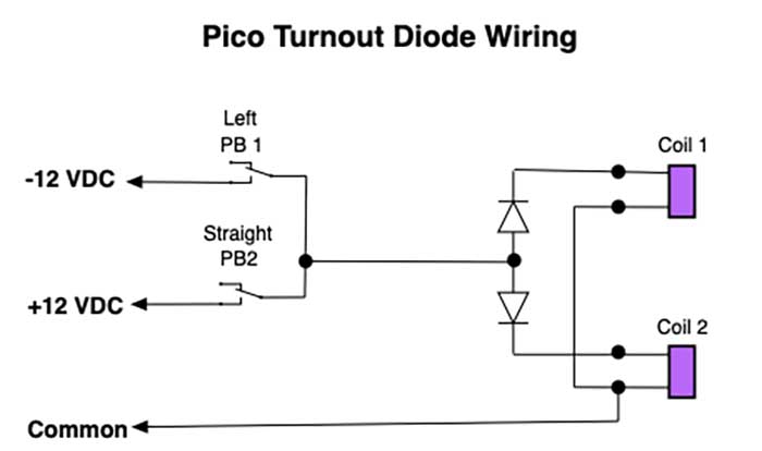
I have one Pico turnout, but it has two coils so a different approach is used there. One end of each coil was connected together and is connected to the 12 VDC common. I connected a diode to the other end of the coil to direct power to the appropriate coil. NO PROBLEM.
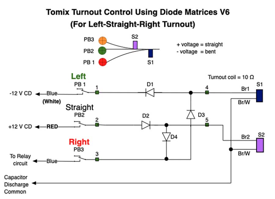
The Tomix 3 way turnouts presented an interesting challenge as I didn't have room for four buttons in a very small space. So, with a 16 volt AC transformer and a diode matrix, I could control the two turnouts with only three buttons. Again, NO PROBLEM.
However, I was concerned (paranoid??) that the cheap push buttons I ordered online might fail (fuse as the high current disconnected) and not disconnect the turnout's coil after switching, burning out the coil and necessitating a costly, and difficult repair. While this is extremely unlikely (???), I am a very lazy person and I don't want to have to replace turnouts. Way too much work!
Originally, I had a very complex circuit that allowed full current for a maximum of one quarter second and then cut the power but a much simpler suggestion was made by one of your readers – a capacitor discharge power supply. This was a great idea and solved a number of problems, but, since I had already built 4 of 5 control panels, created other problems.
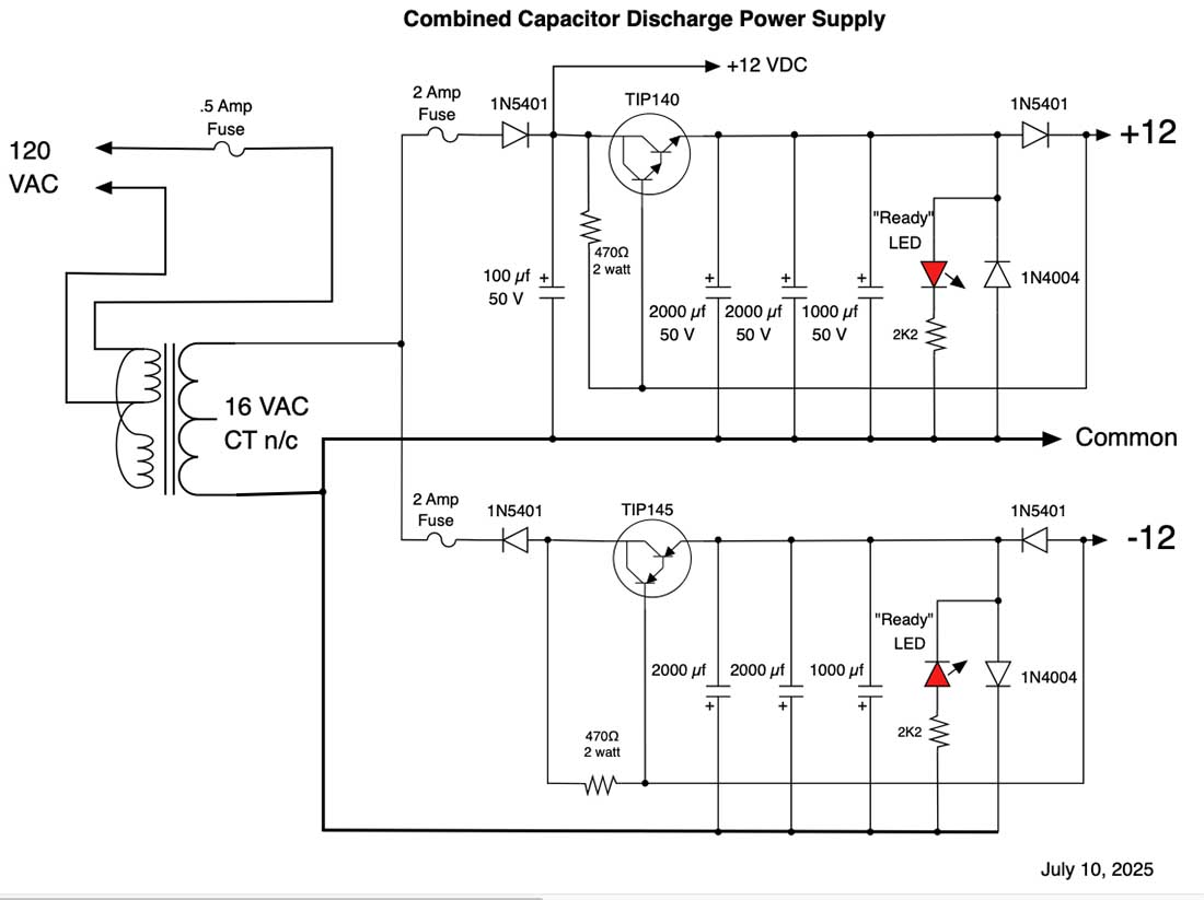
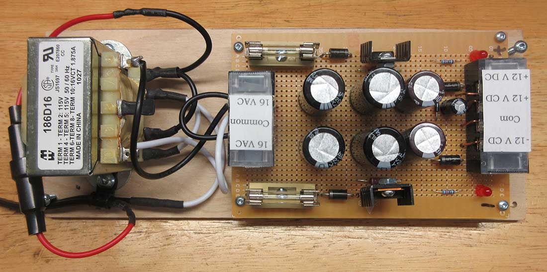
The schematic for the Capacitor Discharge Power Supply is here for anyone to use if they wish. If you need more power, you can increase the size of the capacitors, but these work very well. I have one Kato double crossover which has 4 coils and even with the long wires, the new power supply works reliably every time. NO PROBLEM. (I wish everything was so easy???)
OK, so now I have a capacitor discharge power supply that will work with the Kato and Pico turnouts but what about the Tomix?
Each Tomix turnout was to be controlled by three push buttons and a diode matrix but I could not use the capacitor discharge power supplies. (More hair pulled out. At this rate, I'll be bald by the time I get this layout running. Maybe I can buy a wig?)
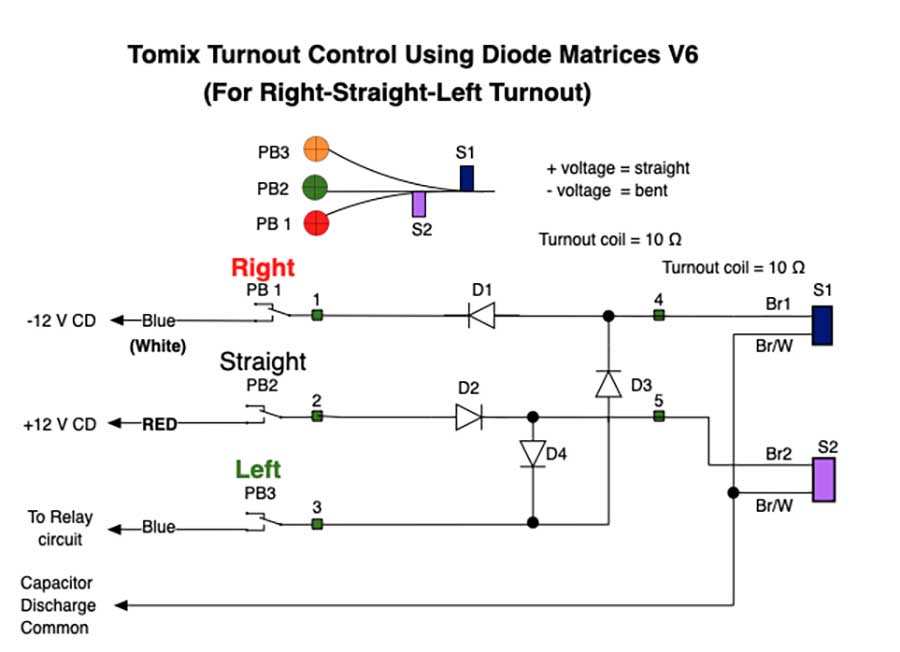
To make matters worse, I realized AFTER I had built the control panels that most of the Tomix turnouts I had purchased are LEFT-STRAIGHT-RIGHT (L-S-R) but I do have one that is RIGHT-STRAIGHT LEFT (R-S-L). Worse, I had already built the control panels with the markings showing it going right first and left second. (more hair lost) The obvious solution was, to align a Tomix 3 way turnout (R-S-L) left, I will have to set it straight FIRST and then left SECOND. If I forget, trains will go in funny places!
After a lot of head scratching, and loosing more hair, I realized that what I had to do was replicate the AC supply with the capacitor discharge power supply. But how? (more hair loss. It's getting cold up there)
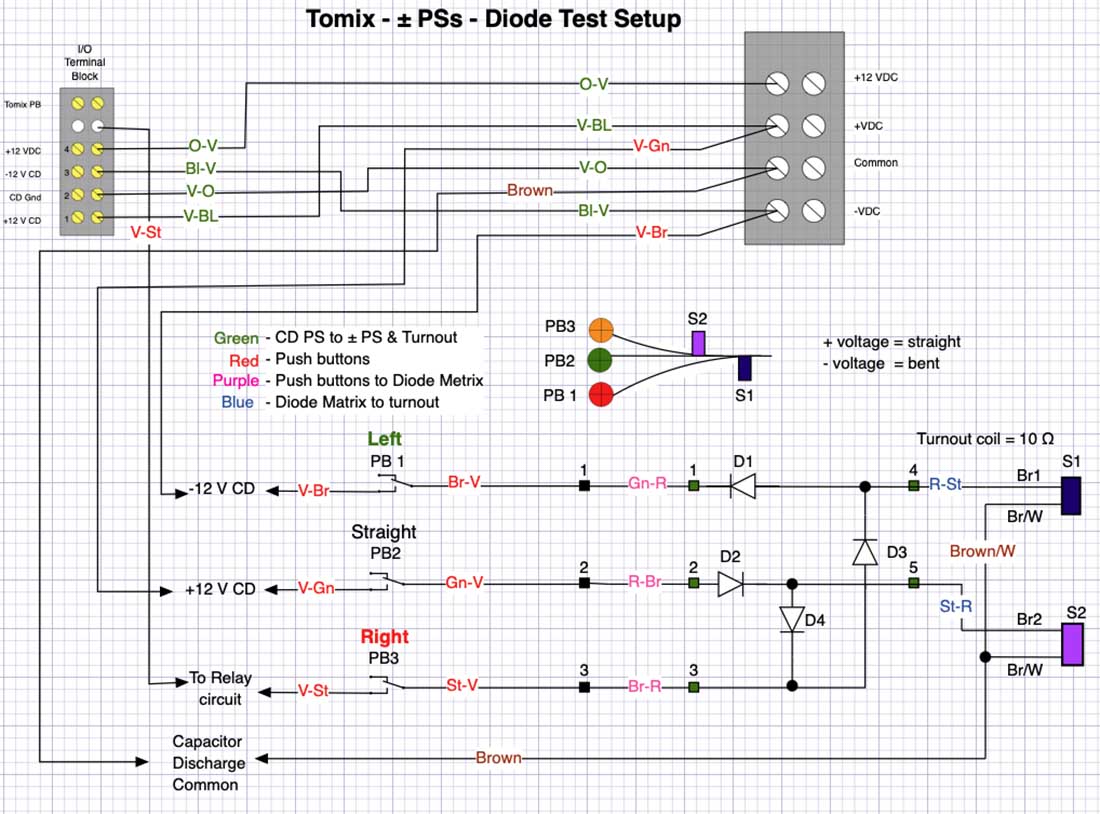
The "problem" is the second turn. Here, a +12 volt FIRST and a -12 volt SECOND is needed to make the second turnout turn. The diode matrix solved that using AC, but a capacitor discharge system does not do that.
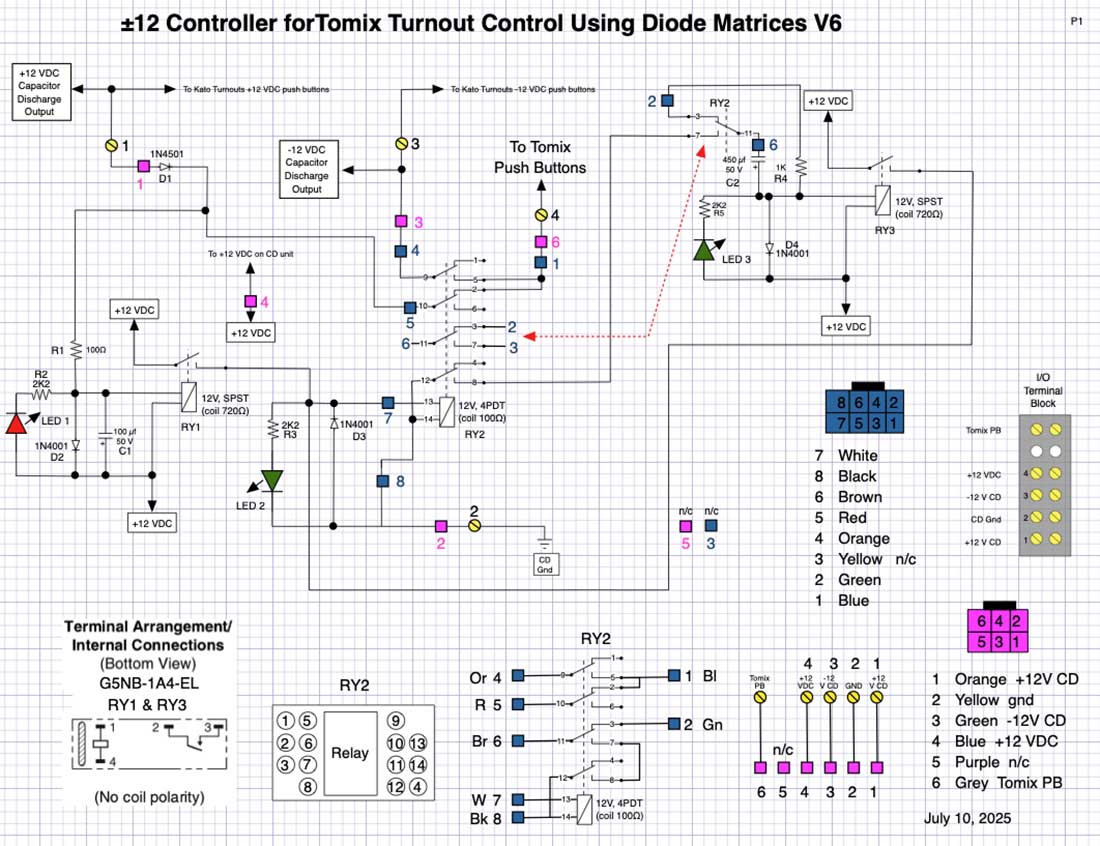
I needed something to first apply a +12 volt charge and then a -12 volt charge. The circuit I developed is not simple, but it does work. (Next time, I'll use more buttons . . . or build another one of these.)
Basically, I isolate the +12 volt capacitor discharge unit from the ± Controller with a diode. When the button is pressed to set the second turn, +12 volts is first applied to the diode matrix which operates the STRAIGHT coils and discharges the +12 volt capacitors. When that voltage goes to 0, a small relay with a resistor/capacitor delay, providing a short delay, energizes, which in turn operates a second transfer relay, disconnecting the +12 volt output from the push button and connects it to the -12 volt output.
The -12 volt line discharges, and a third relay, with delays in releasing, energizes, locking up the transfer relay. Without this third relay, the first two relays would just cycle back and forth.
When the button is released, all the relays release and the power supply recharges the capacitors.
So, it all worked on a test bed, but would a soldered PCB work? The answer was . . . no!
Well, no until I found a solder bridge and a dead LED. Now it does work and am I happy.
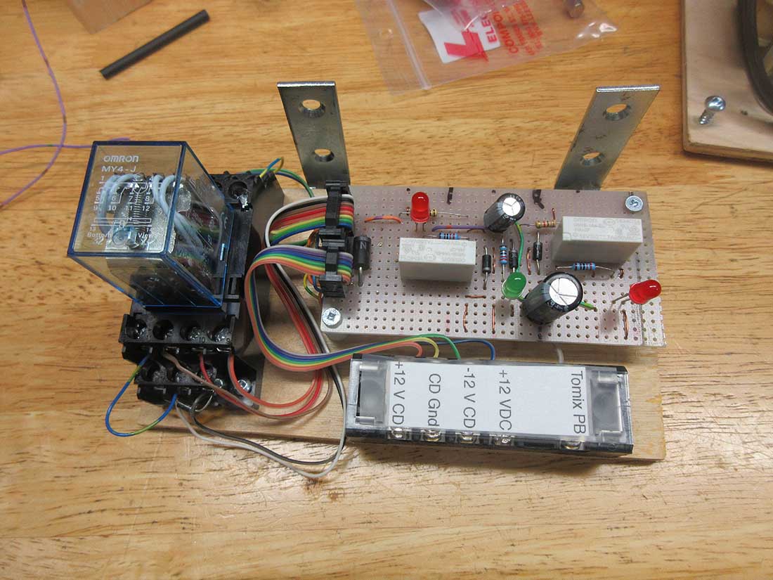
To test everything, I put together a "test bed" using the Capacitor Discharge Power Supply (top right), the Tomix Turnout Controller (bottom right), a diode matrix (top left), a test set of push buttons (top center) and a real Tomix 3 way turnout.
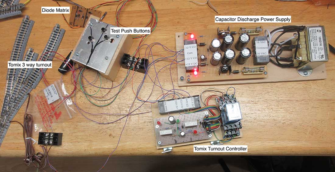
The test was a complete success.
(I think some of my hair may be growing back!)
The diode matrices are different only in which coil is the first to bend the turnout.
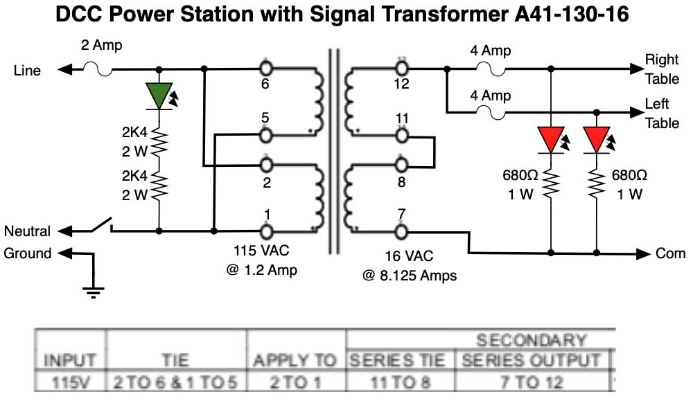
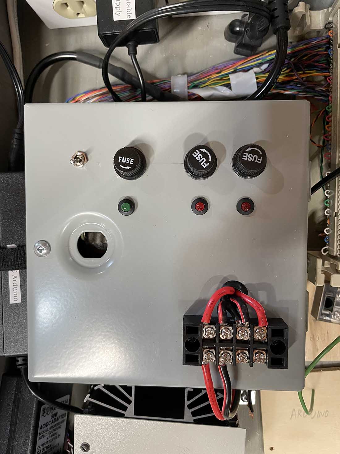
To power my rail empire, I had originally obtained a second hand transformer but realized that it has a 20 volt output. As I am in N scale, the difference in power (20 volts transformer output minus 12 volts (N scale track voltage) times current needed to run) has to be dissipated as heat by the Digitrax DB200+. As they sit in a drawer with limited ventilation, I decide to build a new 16 volt, 8 amp, Power Station that I hope will be sufficient for the whole layout.
A third issue, NOT YET RESOLVED, is how to get Kato (and Tomix) turnouts to let an Arduino (micro controller running the signals) know which way the turnout was thrown.
This has to provide correct position information so that if a turnout is thrown manually or by power, with the main power on or off, the Arduino will know the ACTUAL position of the turnout. A work in progress and probably more hair loss.
I hope this may be useful to others. After all, I have gotten a lot of information, and help, from this blog and its readers.
Thank you all.
Respectfully,
Frank
Surrey, BC
Canada”
A huge big thanks to Frank for putting this together, if you’ve enver scratched your head over how to power turnouts on a model railroad, I hope it helps.
But who can help with Frank’s lastest issue? Please leave a comment below if you can.
That’s all for this time folks.
Please do keep ’em coming.
And if today is the day you get started on your layout, the Beginner’s Guide is here.
Best
Al
PS More HO scale train layouts here if that’s your thing.
Need buildings for your layout? Have a look at the Silly Discount bundle.