Cameron has very kindly done a points and motors ‘how to’ after spotting so many questions on the subject in the posts.
Thank you Cam – and can’t wait to see more pics / video of your layout.
“Dear Al,
It’s been a while since my last post.
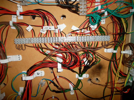
I have spent a lot of time over the last couple of months lying under the layout with wire cutters in one hand and a soldering iron in the other. There is now a big mess of wires under table that reflect a lack of planning on my part. I bit embarrassing but part of the process.
Following is a couple of tips on electrifying points on a layout that might be of use to a few of your readers.
Points and Motors
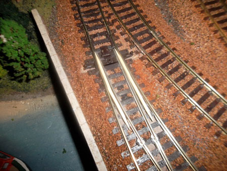
Before I laid the track I drilled holes in the right locations for the point switch rods. I would do this again regardless of whether I planed to electrify the points or not. You never know how hooked you are going to get on this hobby.
I used Peco point motors which have been quite good. Rather than using the propriety plastic adapters I simply bent out the fixing prongs to act as a fixing lug. Perhaps a bit rough but a lot of modelers seem to use this method.
They all run off a 4amp 14v power supply which is not at the top end for this type of point but has been reliable.
Lining up the point motors under the track for reliable operation is one of the more difficult parts of the process. I did however find a pretty good process worth sharing.
1. I drilled two small holes through the top of the layout at each end of the plastic switch operating slide. These holes have two purposes. They provide a reliable guide marker under the table and, if drilled at the right spacing can be used to screw the point motor in place from under the table.
2. I set the point in the central position and held it in place with two tooth picks.
3. Working now from under the layout I lined up the motor so that the motor pin was in the middle ( evenly spaced) from each motor magnet.
4. The motors were screwed in place with a couple of screws and washers.
5. Remove the tooth picks and you should have a well aligned motor.
For me this method took a lot of the guess work out of the process of positioning the motor and ensured a lot less adjustment was needed to get them all working.
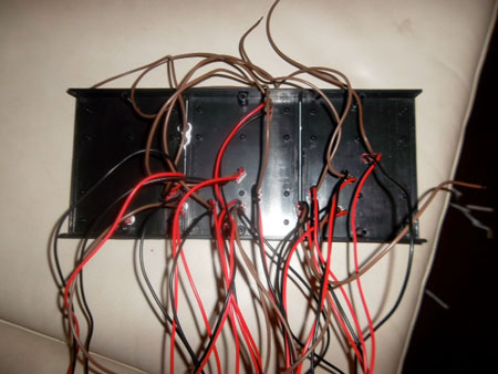
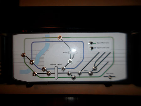
The other aspect of the point automation I thought was worth mentioning was the Mimic Panel. I made this out of a few electrical project boxes bolted together to form up a nice long panel. For the diagram I took inspiration from the London Underground maps. This type of graphic is really easy to read and looks good in colour.
The diagram was printed on paper and mounted on the face of the mimic panel under a sheet of clear acrylic/lexon.
Thats all for now. I will send through a post on the lighting next.
Cheers,
Cameron.
A big thanks to Cam – nicely explained.
That’s all for today folks.
Please don’t forget the Beginner’s Guide is here if you want to stop dreaming and start doing.
Best
Al
PS Latest ebay cheat sheet is here.




Good,sensible information here which I shall adopt. I do prefer the Seep motors though. I also like the layout diagram idea a lot. Where do you get the wiring loom clips shown in the photos?
Like your mimic panel very much. Have you found a passing contact switch that remains pointing in the same direction as the points, so that it serves as an indicator on the mimic diagram? All the switches I have tracked down seem to have a “centre off” position to which the toggle lever automaticly returns after use.
It sounds as though you drilled the baseboard from underneath after laying the track. How do you make sure you don’t wreck the points?
Just in case you hadn’t guessed, I tend to be a bit ham fisted.
Thank you Cam, this is the type of information that I like very much.
Well done
Léo
Thanks for the wiring shot under your layout. Seeing one similar to mine, I feel better already. And THANX again, Al, for being the vehicle for bringing all this to us.
Oh my god.Look at all the wireing lol.That’s some nicely organized wireing.I havent even started my wireing to busy building all the time.Thanks for the pic’s.love the control board,thanks
Cam if you think you have a mass of wires,you want to see mine,it,s like several plates of spaggetti I have used trackside motors be the wiring is
the same, even with DCC you still finish up with a load of wiring,name of the game I suppose.Some great tips well done.
Very timely advice about point motors Cam. The positioning and wiring of point motors can be some of the most tedious work there is especially if you use axillary contacts to detect their position on hidden sidings.
What a great way to make a mimic panel, I’m off to experiment.
Cheers
Ralph
Cam,
The photos of the wiring aren’t bad at all.
They look easy to trace if one wants to make changes.
Congratulations and thanks for sharing.
–Ben Z
Cam do you use a CDU?
I use one on my layout, I also use Peco points and motors ,the P-11 side mounted. You might have seen mine.
Nicely done. I love your panel, with the toggle switches positioned right where they should be. Find it at a glance. Neat!
Also worth noting is the more points you have, the more important to label each active and neutral pair at both ends and may be in the middle if you have a long cable run. I noticed Cameron has done this nice and clear and easy to read.
Dear All,
Thankyou for your kind words. In responce to a couple of questions I can offer the following.
I have used the simple on/on toggle switches. Like alot of you I have looked everywhere for one that provides an indicator but could not find anything very cost effective. I noticed that there are some cicuit diagrams out there for adding LED lights to the mimic board. I think I will go down this track when time permits.
I have found that I don’t need a CDU to throw the points with the 14v 4 amp supply. I did try a PECO CDU at one stage but found it didn’t work as well for me. It could be that I was just simply was using the wrong one.
The white clips that I used to hold the wiring up have come from the local hardware (Bunnings in my casse). Appologies but I have forgotten the brand. I noticed that they have a few very similar ones made by different manufacturers. You can open and close the clip to add more wires as you go. I would definitelly use them again.
I managed to do all the drilling from above. The trick here is to drill the hole under the point slide for the motor armeture before you lay the track. I wouldn’t trust myself to do this retrospectively. The other holes can also be drilled from above for the point motor screws.
Thanks again.
Cheers
Cameron
Nice job.
Really neat wiring,its a relief to know like some,mine is like spagetti junction,the important thing is to label each wire.
Cam, for complete novices you may need to add how you form the hole in the centre to link the pin on the motor to the tie bar. I use the same method as you but found out the hard way. P.S. Using a Common Return on the points and in other circuits reduces the wiring, something else I also found out too late! Thanks Kelvin
I have a portable switching layout with a dozen switch’s and a home shelf layout with 24. All are hand thrown, so I don’t have any trouble with them.
VERY GOOD EXPLANATION
thanks Cam, very informative. I am in the middle of builfding a layout from scratch, 6 x 4ft. After not done any modelling for years. I will certainly take on board your ideas.
Les
Top notch work, only regret is that we cannot see the rest of the layout. If it is half as good as the wiring, I’ll bet it’s a banger.
Would really like to see some O27 layouts. Seems like 90% of your posts are of HO or similar gauge layouts.
I would also like to see some O gauge layouts with the 3 rail track.
Well done Cam
In response to Cam’s Peco jturnout motor fitting, definitely use a CDU. It prolongs the life of the (elecro magnetic) point motors and limits the current (amps) being used. Talking Electronics in Oz has cheap kits, they take 20 miniutes or less to build, highly recommended. Also label every wire you can, I use a good quality masking tape and write on that, very cheap and sure as eggs is eggs you WILL, one day, need to sniff out a problem. The previous comments are based on 50 years experience!
Pete
nice neat wiring but i see no protection for each motor you can buy in line fuse holders or like i did the good electrical one [a bit more expentive ] then the auto mobile type and fuse it for protection so you do not take out all your train set or power pack
1 amp or 2 amp fuses are big enough to use
Hi I am an electrician and have seen professionals do worse
Label all cables both ends also keep a log of same, you will forget any abbreviations. I would also say common all the returns ie neutrals you can use a bare copper wire fixed at each end of the base board. Attaché a large flexible wire around 1.0mm2 where convenient solder it on after several wraps around the bare copper. You now have a bus bar and can attach as many neutrals as you like and keep them short. This can be extended to other base boards, a tail and crocodile clip is all you need. After too many hours lying under base boards I now make sure base boards can tip up to at least 90 degrees from normal rest position
GREAT LOOKING CONTROL PANEL!!!
Best wiring job I never seen.How did you get the lines so straight?
I ask this —> Where are the trains ?
that’s good marking his wiring like this someday he might want to chase down a circuit for some reason and where do you begin without markings for those who have worked on control panels with thousands of wires
Great idea with the toothpicks…….
Cam, I’m 70 and do not like to get under the table either. Try this for your next installation of a switch and switch machine. After finding the final position of the switch mark it well. Temporarily mount the pico switch machine to the bottom of the switch. Cut a hole large enough in the table top so the switch machine will fit and make sure it can be installed with a little clearance around it. Paint a piece of reasonably heavy paper the color of the gravel you are using. Cut a piece of that paper to more than cover the hole you cut in the table. Solder three wires to the switch motor that reach from that point to your control panel. Cut four holes and one slot in the paper and place it between the switch and the switch machine. Install the Assembly through the top of the table the paper will keep the gravel from falling through the large hole. When the gravel is glued down the paper also become glued to the table top. I would make or buy a capacitor discharge unit to throw the twin coils in the pico switch machines. This should solve any problems with the switch motors throwing and will allow you to use 90% of the 4 Amps in your power supply to control anything else on your layout. I spent my entire life servicing electrical equipment and understand the problem most R R have with electronics on their layout.
My working life has been with aircraft electrical power systems and I agree with Andy P. Your wiring doesn’t look too bad, but I would set up a bus bar system for all your common/neutral wires. This will save you wire and help in understanding your wire runs. Also keep a log of your wire runs by labeling the terminal blocks and switches, etc. The more complicated your layout gets, the more you forget where the wires go. Good luck and thanks for sharing your layout ideas.