“Dear Al,
Though I would post the next instalment on lighting the layout.
This is a pretty extensive area normally so I will try and keep it concise if I can.
After the points were in place I decided that I wanted to light the layout.
A previous post, I think from Arnie, pointed me in the right direction with regards to how to control the lighting.
I wanted to have a lighting control dial that I could turn to different times of the day with each position of the dial turning on a different combination of lights. This is how I set it up.
Positioning the lights:
I fixed the lights in place from under the layout so I could take them out and change them without ripping up any of the buildings to do so.
I came up with this cheap fixing method that has worked pretty well.
I first drilled holes for each light before the buildings were fixed in place.
I then made a wire bracket from fencing wire (coat hanger wire would also be fine) that would hold the light in place but be fixed from under the table.
The below diagram and photo better describes this arrangement.
Cam”
Very smart! A big thank you to Cam.
That’s all for today folks.
Please do keep ’em coming – it’s getting a bit thin on the ground this end.
And if today is the day you get started on your layout, the Beginner’s Guide is here.
Best
Al
PS Latest ebay cheat sheet is here.
PPS More HO scale train layouts here if that’s your thing.


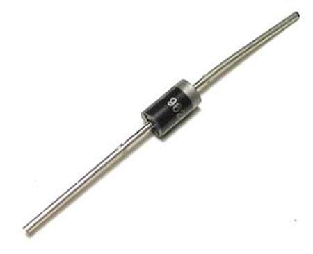


Thanks Cam, very nice. Would you mind suggesting which diode you use. Only some of the numbers are visible in the photo. I think it must be a 1N962_???
Novel ideas. Thanks.
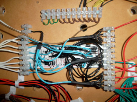
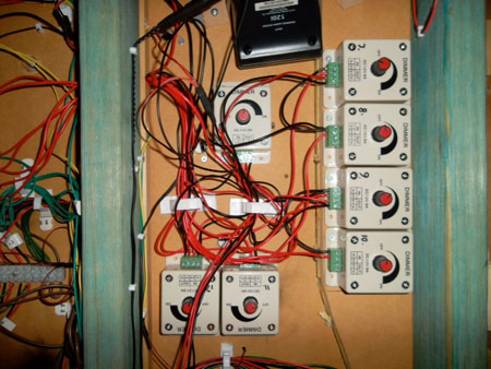
Please explain the wiring pictures [last and 3rd from last].
Are those dimmers for the LED’s?
A great idea for mounting the lights under the layout. Thank-you. Not only will I use this method on the next lights but will begin to re-install the ones I put in already. This method also solved one of my problems with placing a light on top of the inside of a building without actually mounting the light to the structure.
I’ll just use a longer piece of hanger to get the light where I want it.
Bob
Thanks for the wiring tips………..this will help me when I set up my N gauge model railroad…… Ron
Spectacular diagram and a wonderful method for adding light without removing building. Definitely going into my reference file. thanks so much.
What are the white plastic wiring gizmos that look like plastic terminal blocks?
Thanks cam, I am going redo some of my wiring.
cam great idea with the lights. thanks for your idea.
EXTRA NICE WIREING
Oh, yes it does
For Donnell’s info (or anyone else for that matter) typical diodes for this application would be 1N4001, 1N4004.
That’s a fantastic idea, I used hot glue inside the buildings I shall now change some of them as you say its better and more efficient, what are the white boxes.
RESISTORS – DON’T FORGET RESISTORS MUST ALSO BE USED WITH LEDs if you’re using a 12volt supply then EACH LED will require a resistor, otherwise the LED will be destryed.
For a 12volt supply you should include a 560ohm / 820ohm or 1000(1k)ohm resistor in series with one of the leads.
Cheers,
Robert
love the mounting system never would have thought of that
I love the idea Cam, I need to get started before I get too far behind…
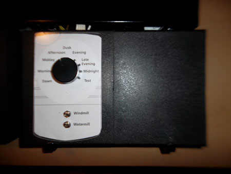
Thanks for sharing a great idea! The snaps that followed the diagrams were tempting – can you explain them? (Use of LED’s, the wiring in the black box labelled “…morning midday afternoon…” and how the under-table dimmers are involved in the system?)
Thank you Cam for your lighting article. I was just thinking about layout lighting the other day, and how best to wire up the layout so as to turn on certain lights before others. (Shades of turn-out relay/switch diode matrix setups). As for the type of diodes to use; If using LEDs, 1N4001 diodes that you can get at Radio Shack, Dick Smiths, (if they are still around), or your favorite electronic supply shop should work without problems. Be mindful of diode polarity. And your way of mounting the LEDs is marvelous. Why couldn’t I think of it? Just remember to insulate the LED wires so that you don’t have shorts.
The suggestion that I offer is to wire the diodes on a pre-drilled phenolic board, all orientated in the same direction but in groups. For easier trouble shooting and servicing, label the groups for their particular area of lighting. (Like for street lamps, store fronts, houses and so forth.) Instead of using a rotary switch, using a bank of lever or slide switches might be better. That way you could turn on or off sets of lights in a different order as you see fit, for different times of day or night..
Cam I was wondering why did you use a diode rather than a resistor?
The wiring idea is a good one and will be redoing my lighting on my new layout.
Thanks for the info.
Hi everyone.You seen some of my thing’s i build,like the tower and many other’s and even how to hookup led’s in your engine instead of factory balbs,anyways i build alot of this’s but the wireing scare’s me.Ive gone threw so far a few led’s and melted a few wires.This is going to help.Thanks for the info.Going to give it a try
Great way to mount lights. To reduce the physical size of the cable groups you can use “wire wrap” cable since the diodes draw very little current.
Cheers Ralph.
Nice idea, good photo’s would be better if you described what was going on, you know captions.
Dear All,
Appologies if the last post was seemed to be missing some information about the setup. The old cut and paste gets the better of us all at times. Hope this helps to fill in the gaps.
The Lights
I have used 12volt LED lights throughout to avoid having to use resistors. I have found that the “warm” coloured LED’s look much better when lit up. The regular LED lights look very blue when you light them up so are better for replicating areas where you would find flourescent lights like sheds and factories. The street lights are grain of wheat type bulbs which draw a bit more current but look the part.
Controlling the Lights
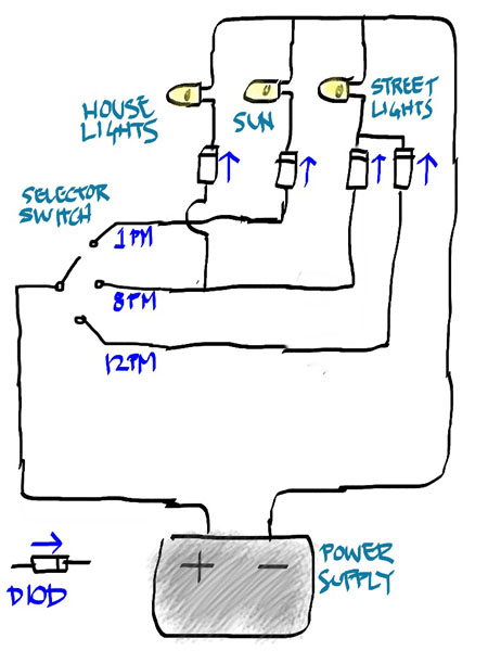
To control the lights I used a “diode matrix” and a rotary switch. There are a lot of posts on diode matrixes. They are often used for throwing multiple points at once. I have fond some of the circuit diagrams difficult to follow so I have draw my own version to explain how it works. (apologies for the spelling mistake in diagram)
The purpose of the diodes is to prevent the current from finding its way to lights you don’t want it to. The diodes will only pass current in one direction. My lighting runs from a 12v 4 amp power supply. For the switch I used a “1 pole 12 position rotary switch” and “3A 100v rectifier diodes” all can be bought on Ebay quite cheaply. You can extend the above diagram as much as you like as long as you don’t draw more amps than you have. If you stick to LED lighting you will be fine.
The “diode matrix” I made using a “bread board” from the local electronics shop. The bread board is good because you simply push each diode into place and cut down on the amount of soldering. The one I got was too small and subsequently messy. I would get a bigger one next time.
I made the swith controler to match the mimic panel described in the earlier post. I did include a combination that turns all the lights on at once to help me test them.
I am very happy with this arrangement because I can add lights to the layout over time without needing to upgrade the switch panel or the diode matrix itself.
Dimming Lights
I have found that sometimes the LED lights are too bright for the building they are in and make the whole thing glow like a cheap Christmas tree light. I looked at a variety of ways to dim the lights by painting them, covering them with bits of paper etc. The best way I found is probably the most obvious. Hook them up to a dimmer. You can not dim LED’s with a variable resistor or they will burn out. Fortunately you can get LED dimmers. The ones I have used are “12v 8A LED light dimmers” also found on Ebay. I mounted mine under the table as once they are set you don’t really need to adjust them. They attached to the lighting circuit between the “diode matrix” and the lights themselves. You can run multiple lights off one dimmer.
The whole lot works pretty well. I am still adding lights to the layout. When they are all in I will do the video as promised.
Cheers
Cam
Cam;
Very nice wireing! Could you relay more information on the LED Dimmers?
Cameron:
You have a flair for hand lettering. Are you an architect or draftsman?
Al: I have found most people throw away their Christmas lights when the string stops working. Testing usually proves only one bulb is bad. These bulbs strings can be cut up with pigtails about 3-4 inches for each bulb. When you wire these in SERIES with 5-6 in each set they work perfect for house lighting. Not real bright and yet bright enough to make your night scene very realistic. Since they were probably headed for the trash can they are totally free. Also they can be connected directly across your controller on fixed DC or AC. What could be better? For the DCC people connect to your 12-17 volt power supply.
I am reminded of an old model railroading axiom…8 wires and 4 relays is better that 4 wires and 2 relays. My layout is slowly progressing. I am using lots of the tips seen here.
I take tissue paper and place it inside of the windows, to hide the bulbs. If the lights are making the building glow tinfoil works great and you can also make some of the windows dark.
If you are a grain of wheat bulb user an old transfomer makes a good dimmer which also allows the bulbs last longer.
pretty kewl will have to try it, but why would one need street lights at 12 pm the sun is still shining
Hi Cam,
You didn’t specify the voltage on your power supply. That is sort of
important unless you like to burn those LED’s out. And you don’t really
need a diode in series. LEDs will work from AC, too because they ARE
diodes. Just need a dropping resistor .
I read a lot of the tips here on line I have really got a lot of HELP from everyone, I`m new at this Just building a N scale layout since I retired. I have some questions for Cam or anyone who can help. I need more info on the electrical work. Which way does the diode go in the circuit? Do you need a diode for every light or 1 for the entire setup. what value are the resistors? I have a 12 volt power supply I checked the output and its 14volts is this ok? If I want to lower it what resistor could I put in line to drop it to 12volts? I have only a little electrical past as you can tell I need help in real basic form. Thanks for all you who help spread the good tips you have learned. Desert Rat RR
I developed a similar method for my model houses and industrial units. Often these are more than 1 storey tall so some way of supporting a LED array was needed.
My solution was to slide a number of LEDs into a clear plastic tube- straws are ideal. The array can be wired so each floor is independently lit & controlled. I don’t fix my buildings and each is mounted on a 1cm plinth for rigidity and easy to handle- not my idea – Each building has a hole that the light array slides into so the lights are at the correct height to light the different floors and areas. You can mix warm white, white or colours for different lighting effects.
Connections lead back to the controller and variable power source. It’s a bit more work but worth the effort.
Great idea . thanks
Cam, what a brilliant idea using a coat hanger wire to retrieve the housing lights from underneath the lay out. I am not up to that stage of my layout so am going to archive this excellent lighting suggestion in my how to folder.
Just wondering if anybody has installed level crossing flashing lights and could give me some how to tips? I got given some flashing lights,some kind of circuit board and wires and no instructions, I am totally bewildered?
Correction from my previous post.
You have an overkill of diodes there. The only one required is the second from the right to prevent the 12pm supply from reaching the house lights. The others have no practical use and the circuit would work without the other 3 diodes
Great work. I have a lighting question. As far as LED’s go technology has been pressing for brighter and brighter LED’s. In most model RR applications I want subtle or muted lights not blind you bright lights, except in my locomotives. Any suggestions on achieving that not so bright look and the yellowish incandescent look with LED’s
I like it, but here I would use Woodlandscenics lighting kits, all the work is done for you.
I have to admit that I am a lazy modeler.
Brilliant Cam you have entered modelers paradise with this fantastic tip and tips and diags and photies cant thank you enough for all comments generated that are good also ( even the naysayers been there done that ) keep up the excellently portrayed explanations of seemly very complex issues Thanks again from a 69 year old young wrinkly cheers from chris in the uk and kind regards to Al also for putting these tips into the real world so we can all create our little worlds safely and cheaply
For those of us who are physically challenged I would change the light mounting method from a screw to a bolt and wing nut. Drill a additional hole next to you light hole. Make it the same size as you bolt so it will screw into the wood and stay in place. start your wing nut and leave a space to slide the U of the bent wire on to the bolt and then tighten the wing nut.
Any future required changes, all you need to do is reach under the table and locate the wing nut by feel, no need to see it to use a screw driver, loosen the wing nut, slide the bent wire off and out.
I may have missed some of the replies but how do you handle the street lights that run on 2 volts with the rest of the system running on 10 or 12 volts? I am electrically ignorant and am using 4 different transformers to handle the different systems and there must be a better way. Any help will be greatly appreciated.
Thank you for the info . I am trying to get started on my first layout , the info is helpful . Seeing things I need to keep in mind during the build . I need to learn this wiring so to have a safe layout . Once again thank you .
Does anybody have combonations of code On their layout.? In the 70’s I had a lot
Of code 100,but now I ave aqquired even more Code 83 . My hobby shop said
There was no problem,but I don’t think it is a good fit, Any recommendations
Would be appreticated.
Danny Marso ,D&WRR
Danny,
There should be no problems with using both 83 and 100 tracks except where they mate.
Check the catalogues for 83/100 track connectors, or try this trick. Crush one end of a 100 metal connector and solder the 83 to the crushed end. That should raise the top of the 83 to the top level of the 100.
Another trick. Plan your trackage to keep these connections to a minimum.
Great suggestions Cam! I’m getting ready to build my long-planned Christmas layout that will have a bunch of ceramic Christmas houses and shops. I decided to use the Woodland Scenics Just Plug Ligthing System on this small layout but had not determined how to get the LEDs into the little houses. Your coat hanger wire mounting method is just the advice I was looking for.
Does anyone know if the Just Plug lighting hubs have the necessary resistors and / or diodes built into them?
Hello everyone, This my first post, so bear with me. First, let me say I am disabled and therefore cannot do any work to building a model railroad. I leave that part to my Grandchildren. I simply supervise them and give advice where needed.
After joining Al’s site for info and ideas to make their layouts better, I read here for updates. I am however, a retired Electronics Engineer with a minor in Computer Science, so designing and building an electrical layout is easy for me. Looking at the wiring done in today’s post I find that there are many things I would have done quite differently. I didn’t notice any mention of using an inline resistor instead of a diode for each LED. Not a good idea as the LED’s can burn out quite easily with a voltage spike. Also, the use of terminal blocks was good for interfacing the dimmer switches into the circuit. As for the resistors, instead of soldering them t the respective leg of the LED, it would be much easier to use a “Terminal strip with an appropriate number of solder lugs for each building and/or area you’re going to light. Soldering the resistors there out of sight and in line with the LED via only as wire take much of the bulk away from each light you use and makes it easier to mount them and wire them. All yo have to do then is create your wire-runs using #20 to #24 gauge wire-wrap type wire with small pieces of shrink tubing placed at intervals along your wire run for each light. Bundling youir runs together and using proper break-out technique will enhance the use of your layout and make it so much easier to do any repairs in the future. I am currently working on getting electrical software for my computer. so I can print out circuits I design for my Grandchildren’s layout and to share here online.
What purpose does the diod serve? I have had it on some lights I buy and some did not. I wired them the same and the brightness seemed to be the same.
Thank you Cam. I just finished building the base for my new layout and I’m about to start wiring the track and lights. LEDs look like the way to go. Very timely. Thank you
Bill
Cam and others….. great work and valuable information on lighting