Hall of Fame member, Cameron, has been beavering away on his new layout again, and shows us how to how to wire a DCC model railway
(If you missed his previous installment, it’s here.)
“Dear Al,
More as promised.
Lanarth – Part 8 Electrics
Scale 1:76. 00
DC
Track Peco HO Code 100
Location – British, Southern Railway, Western Region
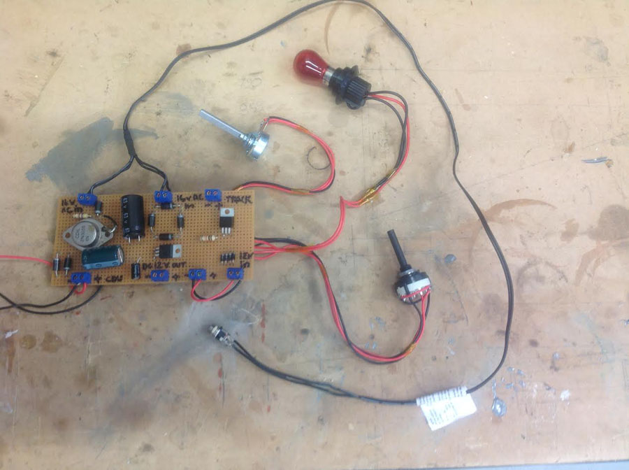
With the bulk of the structures done and the track down it was time to turn my attention to the electrics. As with rest of the layout I thought I might try and build this from scratch as well.
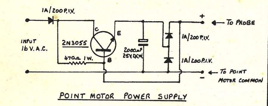
One of the members of our local club provided me with a simple circuit diagram for a controller and a capacitor discharge unit.
I did not know a lot about building circuits so took the diagram to the local electronics shop to get the correct parts then assembled them as per the diagrams.
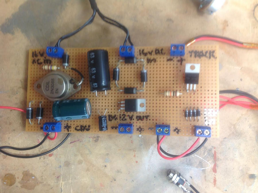
Through good luck more than good management the circuits all worked well. One advantage of doing this myself was that I was able to combine several electronic circuits onto one board.
The final board has the following:
– A speed controller for the track power
– A capacitor discharge unit for powering the points
– A bridge rectifier to convert AC power to DC
– 12 volt power for the layout lighting
All this is supplied by one 16 volt AC power pack that came off an old laptop.
The total cost was less than $40 AUS and I suspect that if I had bought the parts online it would have been even cheaper.
The points are Peco Electrofrog. The point motors are Peco as well with switches to control the frog polarity.
Electric frog points are important on a small shunting layout like this as the locomotive needed is quite short and generally moving at slow speeds through the points.
Regular points like Peco Set Track have a small sections of plastic rail in the middle of the frog that interrupt the power to the locomotive as it runs through. This is not normally an issue with larger locomotives moving at speed but will cause a smaller locomotive travelling slowly to stall.
Cameron”
I do like Cameron’s posts – it’s wonderful to see his approach on how to wire a DCC model railway, and the layout coming to life. I particularly liked the way he took his circuit diagram to the electronics shop – genius!
Next, on to Jim:
He’s been in touch again (his last post is here).
This time he’s sent in a camera train video of his wonderful layout:
“Greetings, Al.
I’m really less than a novice at this but I just wanted to share and contribute to your site.
Jim”
And lastly, Hall of Fame member, Brian, keeps us posted:
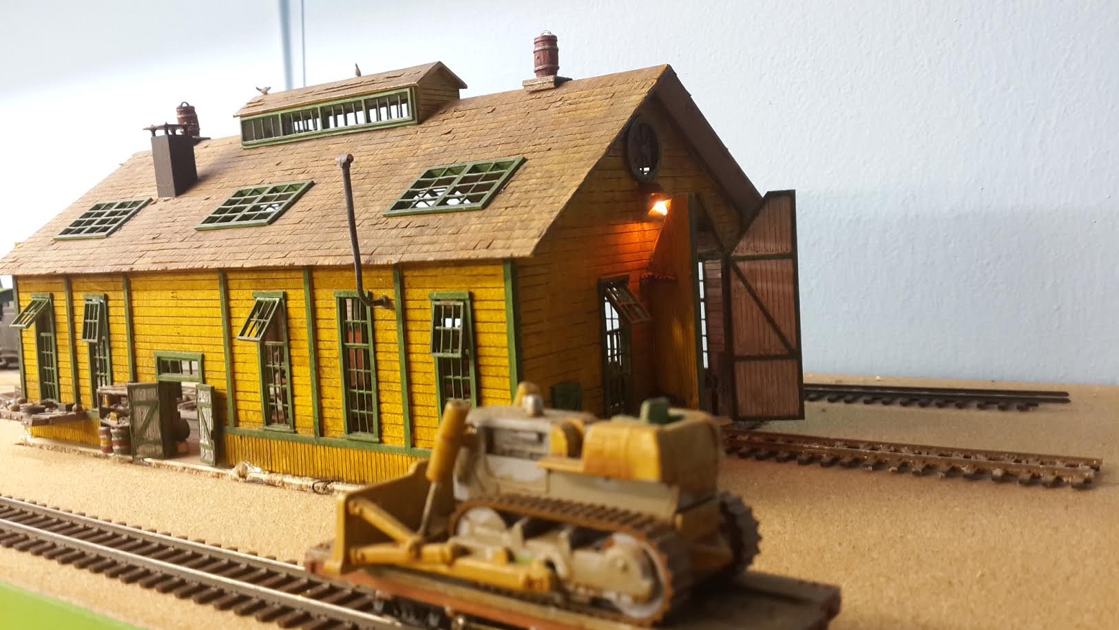
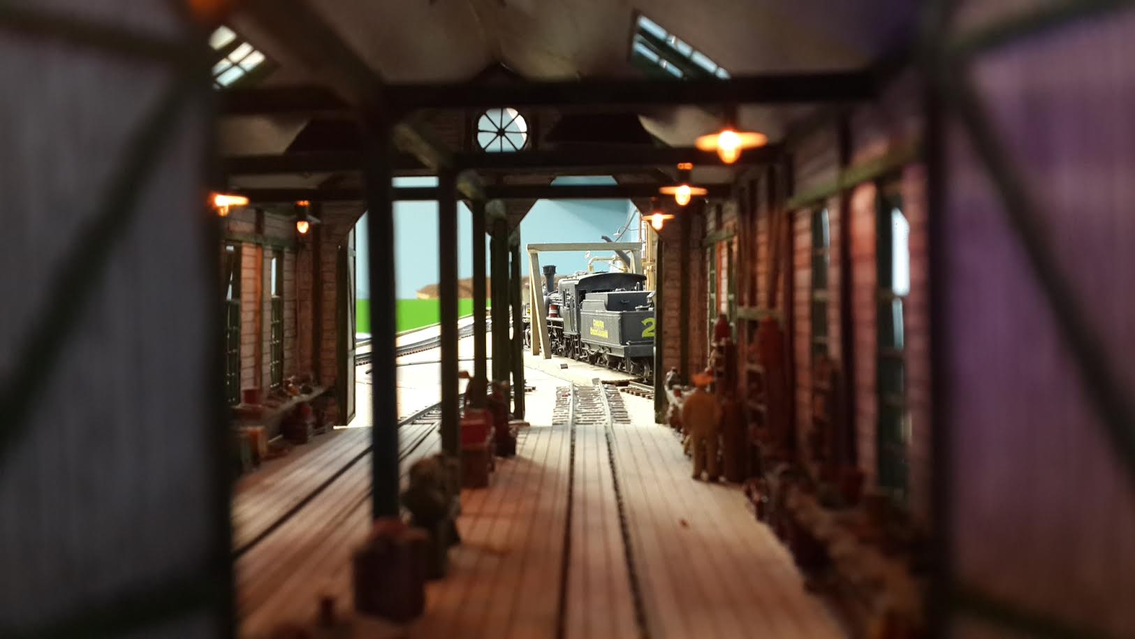
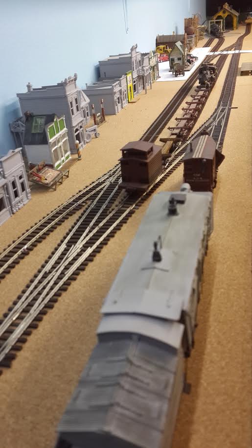
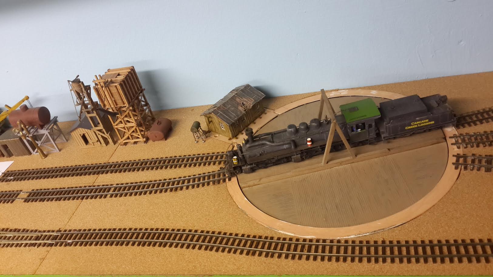
“Hi Al, the next section of the layout has all the track and points laid down, wired and fully operational. The middle section of the ‘U’ is also complete and ready for the sawmill, logging repair shed and extras to be added.
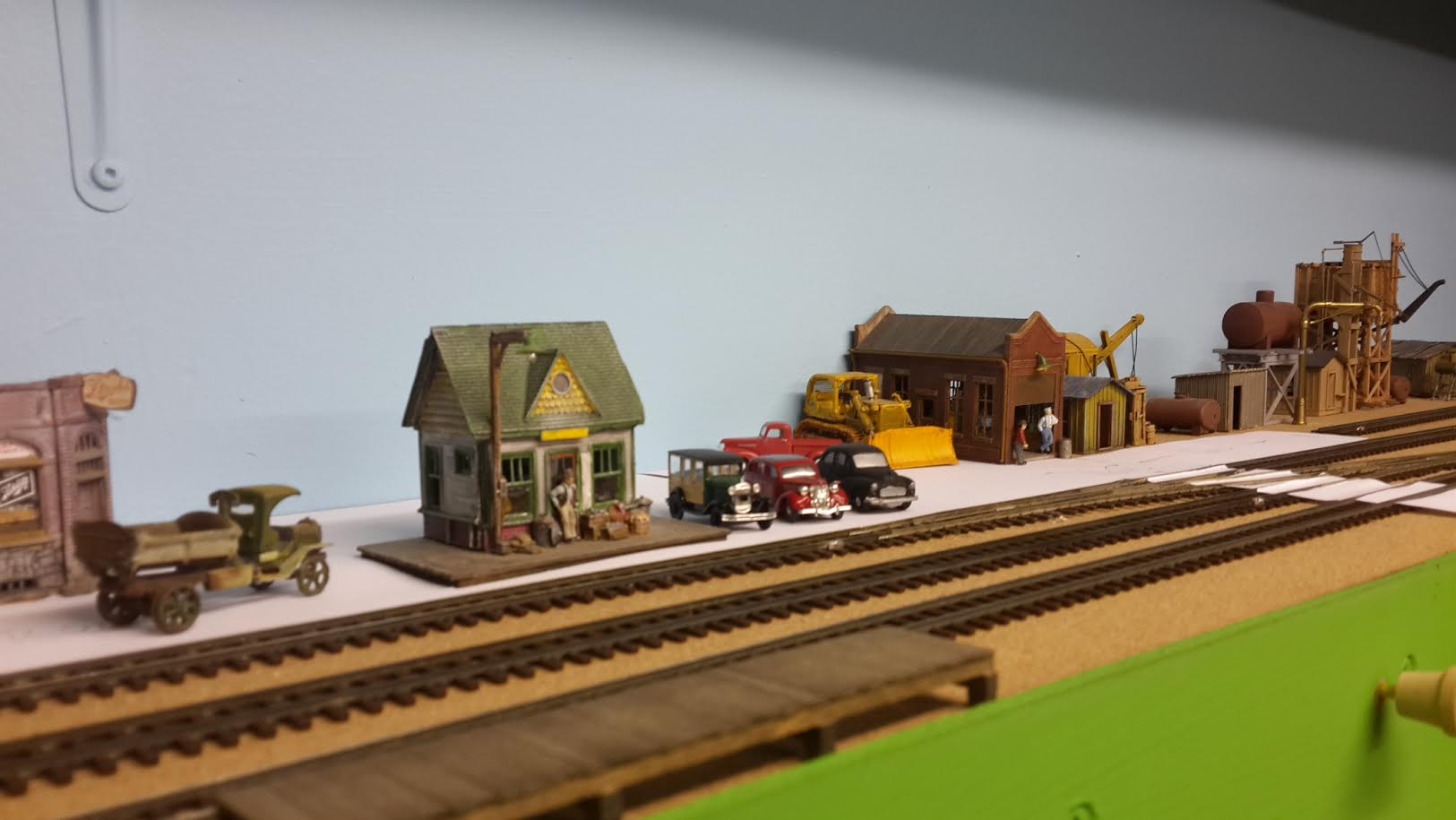
Busy with the town, engine facilities, yard and station. White paper is where the gravel road will be. Once satisfied, will begin with the scenery.
That’s all for now and keep up the good work.
Ps, the 2-6-6-2 locomotive just fits on the turntable with no room for error. (A modified HO Atlas turntable with HOn3 track wired on to it and a Tamiya gearbox mounted underneath the hut to power it).
Brian”
A big thanks to Cameron for showing us how to wire a DCC model railway.
That’s all for today folks.
Please do keep ’em coming.
And if today is the day you get started on your layout, the Beginner’s Guide is here.
Best
Al
PS Latest ebay cheat sheet is here.
PPS More HO scale train layouts here if that’s your thing.

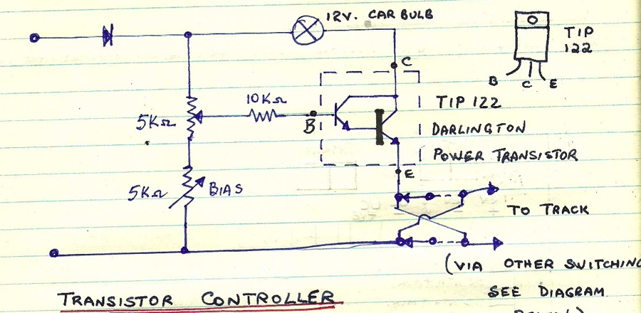
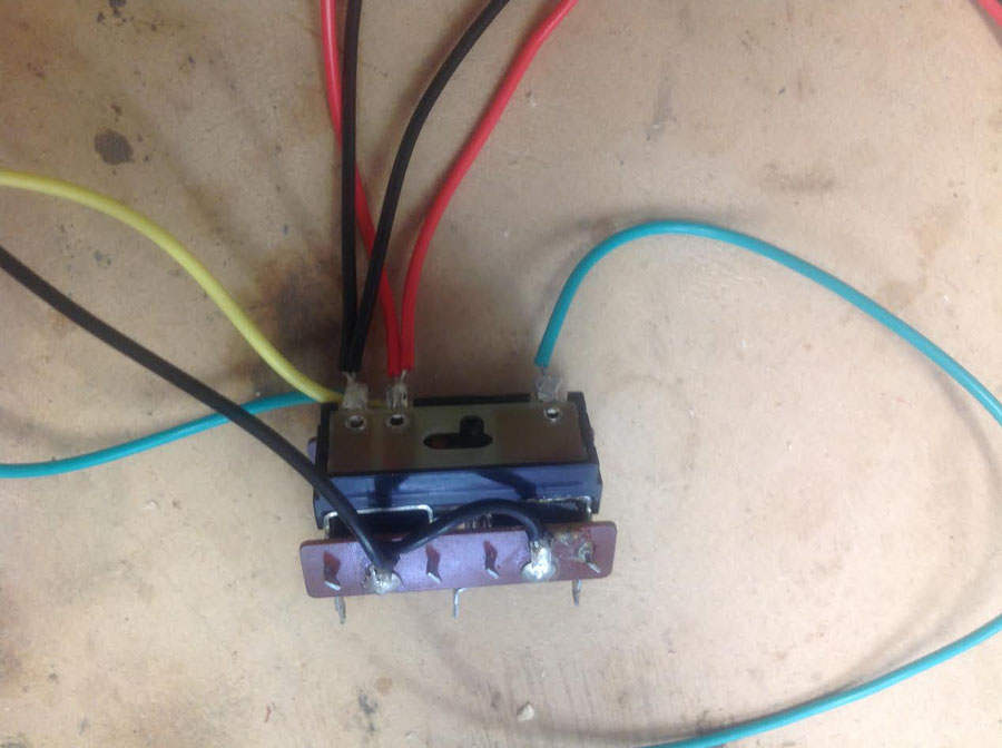


Hi, the transistor controller circuit as shown has the polarity reversing switch wired incorrectly. The left hand supply contacts need to be moved to the center two contacts then flipping the switch will reverse the source polarity to the tracks. The crossover wires are correct,
Nice to see hand drawn circuits again. Thanks, Joe
Very instructive…..thanks again….
Very nice ,just a hint, if you install capacitors let then stand upright. It help with heat dissipation and you save space on the board
Hi Al. I believe Joe is right about about the polarity switch wiring being drawn incorrectly. Good eyes, Joe! But I think the true fix is to remove the track supply wires from the right hand set of contacts and to reconnect them to the corresponding middle set of contacts. Hope this helps. Sal
A few things: calculate the worst-case heat dissipation in the two transistors, and add adequate heat sinks to keep their temperature below 60C (so you don’t get burned on them and so the transistors don’t die).
What is the cold, and hot, resistance of that light bulb? It looks like about 5W which would give a hot resistance of about 30 ohms, which would suck up a lot of power that your engines will need. Remember that a light bulb’s resistance changes a LOT when it gets hot.
Add some 15V or 20V zener or transzorb diodes to the outputs. You are switching reactive loads and they will spike on turn off, destroying the transistors. Twist the wires to the actual rails or points to minimize the reactivity.
If you are using a 2N3055 you must expect higher currents than that 1A diode can handle. Make sure about that!
I don’t know what you mean by “probe” – if you mean a pointed metal stick you can touch things with, expect to make bright blue sparks as you discharge that capacitor into ground! You might want to limit the maximum current somehow.
Use power fuses! They don’t protect the electronics, but they will stop things from catching on fire when bad things happen.
electronic shit baffles me….
Im glad somebody knows about it….
keep em runnin fellas
stjohn in long beach calif
Really interesting, helped me a lot. This is extremely helpful. Thanks.
Finally getting started with my layout after many years of waiting.
I decided to do modules. Do you have any posts on building modules? I would appreciate any information on building modules you might have. I’m going to build them in N scale. Thanks again for all the knowledge that you have supplied over the years. Jim, New Jersey .
I don’t even have an HO train layout, but don’t you think there is a safer way to package these components. If you invented these gadgets, have them patented. You may even get funding.
Hi, the comment about capacitors heating up should really apply to the resistors, they are more likely to heat up, but capacaitors shouldn’t ever heat up – if they do replace them. The comment about standing them on end is really useful, both for heat dissipation and space reasons.
Congratulations for going to a shop and getting the parts and doing it yourself.
reminds me of building my first valve radio at age 11 in 1951.
Lindsay in Nz
There is a big problem with Cameron’s Transistor Controller. The wiring of the toggle switch at the output is wrong. It won’t do anything. The outputs to the track must come from the center terminals on the toggle switch. As shown, nothing will happen. That 12 car bulb will pull at least 1 Amp and is not needed at all. Omit that.
Please advise your readers.
Hi, Keep up the good work Cameron. I ‘hate’ wiring, I always get things switched backward, so leave that part of the layout to my son-in-law.
In response to Jim from New Jersey ….. go to ntrak.org and you will find everything you need to know about building modules for your N scale stuff. You do not have to set up your modules as they do with the 3 tracks up front. I have added one additional thing to where my modules join, small dowels and corresponding holes, to help keep everything lined up.[drill a hole thru both modules AT THE SAME TIME, glue a dowel in one side, leave the hole in the other. I drill 3 sets of holes, with 2 of the dowels on one side, and the center one on the other module.] Automotive connectors that snap apart are great too. Very easy to work with. Have fun!
It is truly good to see a hand drawn schematic! I thought that skill was almost gone! And yes, the polarity switch is indeed miss wired as others have commented on. One way or the other you end up with a set of wires making a X on the switch. I like to use the moving switch contact (middle connection) to track. I would suggest replacing the light bulb with a resistor with an equivalent resistance as a hot bulb and also an appropriate wattage. I assume the resistor is to limit the supply voltage to the power transistor. For defining the wattage required for that resistor, figure the highest current you intend to draw for your engines, and then multiple it as follows: I x I x R, with I in amps, and R in ohms. That will give you watts. I would also suggest an LED from the plus supply to ground to tell you your circuits are hot. Again, you will need an LED and a resistor sized appropriately, If your supply is 14 to 16 volts (which it might be from a old computer power supply, subtract the on voltage rating of your LED and then divide that voltage by the rated current of the LED to determine the required resistance. A quarter watt, 20% resistor should work just fine here. Mind the polarity when soldering the LED. And I sure would use a heat sink on that TIP resistor. I have use a lot of these over the years, and they do like a heat sink, especially if you have shorts on the track!
Back in the mid-60s model railroader magazine had some great transistor throttles very easy to build build the simplest one first.Then add some current limiting resistors that poor base power from the Darlington transistor to limit your maximum current do whatever you want want up to 3 A. The light bulbs works but it’s old-school.
I would also use full wave bridge rectifier’s from your AC power supply for both circuits it will improve the efficiency.
Also if you go online there are many circuits for what you’re trying to Do.
Have fun and be safe.
Looks good.!!!