Had this wonderful lighting ‘how to’ in from Mark.
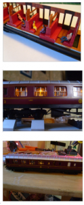
What I love about it is the difference such a small detail makes on a running train.
Big thanks to Mark and please do post a comment below.
“I always wanted to make my coaches look more realistic. I thought they would look great properly detailed and lit up for all to see. The problem with that is, if you are using DC, the best time for your handiwork to be admired is when the train has stopped at the station; and if it’s stopped, then there is no power to the rails and consequently the lights have gone out! Now my teenage son is interested, and I have more time for my hobbies, I thought it was time to tackle the problem. We (sort of) succeeded, so I thought I would share the method, and maybe it can be improved further. Let’s get started with what you will need.
LED’s. Whichever colour you prefer. I tend to think yellow is best for older rolling stock, white for more contemporary coaches, and warm white somewhere inbetween. The brightness can be controlled by varying the value of the resistors you use. I get them 100 at a time from Ebay, 3mm dome shape, round about £4 a packet. The longer of the two legs is the positive side.
Resistors. Again, you can buy large quantities for very little. I find 270 ohm and 680 ohm work well for me, but by all means experiment with slightly larger or smaller values if you want. You can afford to blow some LED’s when they are only a few pence each.
Copper coated stripboard to mount the components on. 1mm holes at 1mm apart.
A W06 bridge rectifier. A natty little box that provides a fixed polarity for your LED’s, regardless of the polarity you feed in. Don’t be tempted to buy the first ones you see as they are often silly prices. By waiting and watching, I picked up 50 for £10 including the postage. The top of the rectifier is marked with a “+” so you know which leg provides the positive.
A dual layer capacitor. Best to think of this as a short term rechargeable battery. It charges while there is power to the rails, and discharges to the LED’s when the power is off (You’ve stopped the train at the station). The capacitor needs to be 5.5v, 0.22 to 0.44 farad. 0.22 farad will charge quite quickly, but will only keep the lights on for a short time. 0.33 or 0.44 will last longer, but will also take longer to charge in the first place. You should get 2-3 minutes of lighting from a 0.33f with a 30-60 second charge. Look carefully online and you can expect to pay about £6.50 for 10 x 0.33 farad capacitors.
Wire. 7/0.2 equipment wire is fine. You can even go smaller if you want. My soldering skills aren’t good enough to cope with anything smaller gauge I’m afraid.
Obviously you will need a soldering iron and some decent solder, along with wire strippers etc. Because my soldering is far from pretty, I normally use a multi-meter to check my work as I go along.
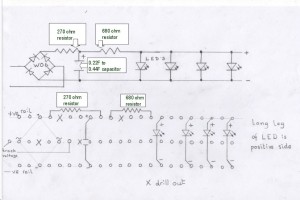
Below is the diagram for the unit, and I’ll refer back to it as we go.
There are 2 ways to go; make a unit with LED’s mounted to go the full length of the coach, or make a short unit and connect that to LED’s mounted another way.
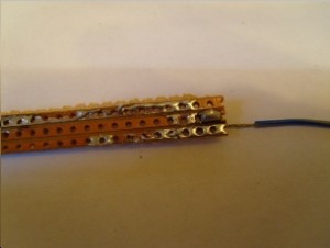
Whichever one you want to build, just make sure your stripboard is at least 3 “lanes” wide. Often I find if I try to cut it 3 wide, one of the edges starts to crumble half way through construction, so 4 wide is easier for me. You may want to work out where your “drilled out” holes will be, and get them done first.
With that done, just follow the diagram. Start with the first lead connection to the board. This will bring power from one rail to the centre lane of the board.
Remembering to feed in from the back, feed your W06 bridge rectifier into the board. “+” to the positive (top) lane, the opposite leg to the negative (bottom) lane. One of your side legs will go in the hole next to the lead you just soldered in, on the centre lane. The other side leg also goes in the centre lane, but the other side of the “drilled out” hole, as in the diagram. If you don’t drill out this hole you will be supplying power from both rails to the centre lane and it won’t work because you are creating a short circuit. Push the rectifier into the board as far as it will go and solder all four legs in place. Again, be careful to not let your solder spill over the edge of the lane it is intended for. Cut off all four excess pieces of the legs when done, and drill out the next centre lane hole (if you haven’t already done so). Now solder in your second power wire to the centre lane. You can solder both side legs into the same holes as the wires supplying power from the rails, but my soldering isn’t that good. Your centre lane is now complete. Yay!
Work your way along the positive (top) lane as per the diagram. Again, the left leg of the first resistor could be soldered into the same hole as the positive leg of the rectifier, if your soldering is up to it of course. Again, remember to drill out the next hole if you didn’t do it at the start, cut off excess legs after soldering, and check to make sure your solder hasn’t crossed over. If you check this after every step, you will know precisely where the problem is if there is one. Leave the checking to the end and you could be left guessing. The next resistor on the top will finish that lane as far as the main unit is concerned. (Don’t forget to drill out again if you didn’t do it at the start).
The capacitor has 2 legs, one for the top lane and one for the bottom lane. It does not touch the centre lane at all, but sits above it like a bridge. The side marked negative connects to the bottom lane.
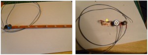
If you’re making a full length unit then go ahead and solder in your LED’s where needed. The long leg of the LED connects to the top lane. If you need to fold the LED flat to hide it you can. They tend to fold quite easily up towards the board, but not sideways. Cut the excess legs and check your solder. Test by touching the wires to the rails, give it a short charge, and take the wires off the rails. If you’ve done it right, the lights will stay on (although slightly dimmer). You can now fit into your coach and connect up to whichever bogie pickup method you prefer.
If you’re making the unit only, connect 2 wires (1 to the top lane, 1 to the bottom) to carry the current off to your already/remotely installed LED’s. Test as above with a single LED and you should be good to go.
I have found that yellow LED’s do dim rather more than white ones when the power is removed. It’s probably due to the different resistance between the two colours, but I decided I could live with it. I did also try the lovely self-adhesive LED’s that come on a roll. Although they are ridiculously easy to hide, they dim an awful lot when the power is taken off. I tried various ways to compensate for the difference in the bulbs, but I just couldn’t make it work. If someone else can get it to work please let us know. I would rather use those as they are so much easier to work with.
Mark”
And now I’m going to do something I thought I never would.
Slowly over the years, I’ve been getting more and more mails from mails from folk trying to find old posts.
I’ve always resisted putting a search box on because I don’t want this to be just another train site. But as the blog grows, it costs me more and more to run it. I don’t mind the time (I enjoy it). But as the mailing list grows, so do my costs.
So what to do?
I’ll tell you. The search box. If you’d like to ferret through years and years of posts, and find all the ones relevant to what you’re doing right now in your layout, you’ll love the ‘search box’, which I’ve called the Golden Key.
But it comes at a cost. Sorry. Don’t worry though, it won’t break the bank – just $19.97. And that’s for life too. So one payment gets you a life time of searching. You can search until the cows come home, it’s yours for good.
You’ll also be supporting this site too because it’s starting to dig in to my coffers a little too much for my liking (and way past breaking point for the ray of sunshine known as Mrs Lee.)
Here’s what ‘the golden key’ will do for you. Press play and have a look:
Anyhow -I’m sure it will help some of you out, and it will certainly help me out. You have until Tuesday if it tickles your fancy.
That’s all this time folks. A big thanks to Mark.
Latest ebay cheat sheet is here.
Best
Al


Just a quick note. The black band with little blue rectangles in, on the side of the capacitor, marks the NEGATIVE side. Make sure you fit it the right way round.
Good job,
This method of lighting provides another benefit – the coach lights will light steady and not flicker as the coach rolls over dead spots.
very interesting trick to power lights in DC! Not sure if this will work for my scale (N), but undoubtedly, a great technique. 🙂
Brilliant and easy reading with pictures to clarify. I will keep this one for reference later. The experience with colours and type of LED very usefull.
I am now thinking what else can this type of light control can be used (train lights front and rear etc;)
That’s a great idea I have thought about doing this with a small rechargeable battery but I thought it would send false power back to the rails your system is best !!
Thanks for the capacitor trick on the coach lighting, I’ve wondered which way to do it, ie rechargeable battery. Here’s a good place to shop for lighting on e-bay – wehonest.com They sell variable voltage LED with a variable resistor built into the leads. They can run on 1.5 volts up to 12v dc and maybe even higher. Lighting both gow and led is dirt cheap including block signals w/built in color controls for yellow.
Ed C
Excellent how-to, Mark! The use of the bridge rectifier is simply genius as it solve two problems; not only does it convert forward and reverse power to the proper polarity, but also prevents capacitor discharge from back-feeding to the rails.
Caution! When purchasing electronic parts, be sure and get the ones that don’t have miniature flashbulbs, fire crackers or excess smoke packed in them. They can be very annoying. Nothing sticks out like a smoldering crater on a PC board……………… Thanks for the tip Mark, I didn’t know the caps would hold a charge that long.
Thanks for the comments all. Glad you like it. Of particular interest to Frederick, I did make one with a self-contained red LED unit (self made of course) with a fibre-optic strand through the back of a lamp on the back of a brake third. It worked, but running two different colours off the one board really sucks the power out of the coach lighting. If I can find a way to colour the existing white/warm white/yellow and then put it through to the lamp on the back I will let you guys know how to do it. Unless if course somebody beats me to it, in which case do tell please. Thanks for all the tips from you all in the past, keep it up.
Thanks for a great write-up! I’m knowledgeable on household AC and basic DC, however, my knowledge beyond that (capacitors, resistors, etc.) is sorely lacking. Can you recommend a book which I might use for education? If would have to be at a level an author might use for “DC For Dummies” or the like. Thank you!
Hey guys,
Can any of you suggest how I might find model buildings 14-18 from Homes of Yesterday and Today? I have tried Craigslist, E-bay, and Amazon. any suggestions are appreciated. thanks. Dennis
Art I wish I could. I have ideas and then rely on my father’s 40+ years as an electronic warfare specialist to help me turn it into something that works. I’m still trying to find a book or course of some kind to improve my knowledge myself. You could try “IC 555 Projects” by E. A. Parr for some interesting things to make yourself though
To Art Risser.
Art you night try looking into the “Heath Kit ” line of products. They were able to make even me understand Electronics. They have many little kits that you can get from them that actually make something work. They have some very intricate products also They take you from A to Z . The prices are not exhorbitant either
Hi Mark
That looks like a great system. I was wondering about the capacitor sizes, 440,000 microfarads (0.44Farads) is a pretty big capacitor . A rechargeable button cell would occupy less space.
Cheers
Ralph
I may have missed it but how do you connect the power pick ups to the wheels?
Hi Mark
Thanks for that “How-to” very informative.
Al – the Search Function will be extremely useful , excellent facility (- paid up already ! )
Cheers
Gavin
Ralph, I did have a little paragraph on purchasing capacitors, didn’t make it in maybe on space grounds. The last lot I bought were 0.33 Farad, 9mm x 4.5mm, 5.5v. I didn’t think that was especially bad when you’re getting almost instant charging. Body sizes vary by manufacturer, so pay attention when ordering, or you could end up with something 2 inches across. Capt Jim, I didn’t cover wheels and pickups. There are so many ways of doing it and most people have a preferred method, so I thought it best to leave that alone. I put a spring on the axle of a metal wheelset. They are insulated at one or both ends already.If insulated at both ends, use some silver conductive paint to connect the axle to one of the wheels. Solder your pickup wire o the spring. To pick up from the other rail use another wheelset the other way round. If you can fit it in, a wheelset insulated at both ends can be used for pickup from both rails at the same time with some copper or phosphor bronze strips attached to the underside of the bogie and pressed against the back of each wheel. Solder the wires to the strips to complete the pickup.
Hi Mark, I just added lighting to some of my coaches, I used a button battery and holder, a very small switch that I located under the model and wired it up to three leds, I tested the battery and I got about 25hours before it started to fade, like yours it gives a warm glow , very realistic.
The cost was £3.00 and a bit of soldering, the only thing is , I have to manually turn them on and off , but I don’t need power from the tracks.
I hope this helps the non electrical minded like me.
Thanks Mark
I must say that I prefer the capacitors because of their rapid charging and no need for a switch as they will eventually discharge if left inactive on a siding without needing to be switched off.
Cheers
Ralph
As I recall, many carriages used on secondary services had reasonable light from the dynamo as long as they were moving at a fair clip, but once the speed fell you went back to battery power and the lights would be down to a yellow glow,because they didn’t do enough mileage at speed to keep the charge up. So, maybe you only need some of the LEDs fed from the capacitors.
Al, if I started searching through all the old posts I’m sure I’d be sitting here all day!! Thanks for all your efforts though, and tell Mrs Al it keeps you out of the pub.
Rod
THAT IS A VERY GOOD IDEA.
Hello Mark,I am dummer than a rock when it comes to electronics, I am making a list of the items needed to light my cars, I am joining your golden key page this coming payday,( apr 1st),please extend the “cut off”period so I may join, you are a genious my friend!! Thank you!! Mike Wilson,,Arkansas USA
The cap is great for allowing for dirty track and such. However if you are running your trains on DC (no DCC) you could always put three diodes in series with the locomotive motor. What this will do is to make the train start at .7 volts above when the lighting is stable. Say you locomotive can run down to two volts. Now you have raised the locomotive run range up to 4.1 volts. The led lighting will work down to 2 volts.
What I would also do is to add a 3.1 volt zener diode across the led feed. The cathode goes to the positive lead of the leds, while the anode will go to the negative lead of the leds. This will regulate the voltage feeding the leds and keep them constant in intensity.
My mistake. Put the 3.1 volt zener across the cap, with the cathode to the + of cap.
This will regulate the voltage to 3.1 volts.
Thanks for a great tip and easy to understand instructions. I’ve saved this tip to my computer along with all the comments and will be definitely “giving it a go”
David
Great tip thanks. Check out the LED strips available on Ebay etc. They can be cut to length in multiples of 3 LEDs. very easy to use and have a low profile too. “Yellow White IP33 Light Strip Flexible 300LEDs DC 12V”
Re power pickup for coach lighting and the use of springs or blades to wheel flanges; I suggest the use of conductive wire, phosphor bronze springs (oh yes) to mind, preferably making the lightest connection to axles rather than wheel flanges (less wheel braking effect and potential contamination).
Re the use of a zener diode across the capacitor, great idea: by increasing the zener voltage to say 5.1 V and raising the 680 ohm led feed resistor to 1.8k, the capacitor is still protected from over-voltage damage and light intensity stabilised whilst the led runtime will be increased. Varying feed resistance varies led brightness (experiment ok, you will still get useable light from the leds using 3.3k)
Great little blog, unfortunately you lost me in the diagrams. I was understanding it right up to the pictures then I lost it.
I’m gonna ask Frank (our sparky) when I see him next week. He understands all the techy pics😐 maybe he will be able to explain it better to me in simple talk 😀
throw me a lifesaver it’s over my head ! I’ll buy store bought.
thanks for the time though lol.
Just a word of caution.
These supercapacitors store a serious amount of energy and if they fail they will fail big. Sufficient to cause damage to the coaches or you.
The resistor values quoted are safe for the 5.5V capacitors used as they give a charge of about 4.5Volts. Trying different resistors is unlikely to damage the LEDs it is more likely to over volt the Capacitor and/or allow too much initial in rush of current and burn out the first resistor. E.g. the 0.44F capacitor will initially draw 0.5Watts through the first resistor so you will need a half Watt type not the usual quarter Watt. Bigger Capacitors exacerbate the problem.
Having said that IF you follow the advice strictly using the values given and use a half or 1watt resistor as the first one. This solution works a treat for both DC and DCC.
Cheers
Mal
I believe the problem with the strips is that each “bulb” is actually 3 or 4 LEDs in series so that you don’t need the second resistor when connecting to a 12V supply.
The problem is the Cap is only charging to 4.5~5.5V and so the voltage drop across the strip LED is higher than the supply. They simply don’t work when the input voltage is not high enough to overcome the respective sum of the LED drops.
Let’s think of a different solution and post it here.
I shall go and have a play when my 1F capacitors arrive.
Regards
Mal
For DC all you need is to wire to a resistor, capacitor, light bulb on the positive side. On the negative side you need to wire in a diode. The diode keeps negative voltage from coming in on capacitor. Light will not work backing up but who really cares. A very simple way to add lights to passenger cars
A cautious note on the above circuit, There is no safety net with overcharging the supercap. visit coach-lighting.com where the pcb incorporates built in safety features.
Great idea Thanks PS the Capacitor values is in Micro farads. A Farad would be a foot in diameter
Fantastic Idea and easy to understand after you do it. Be Safe!
Al, I’m glad you found a way to permit yourself to take in the money people are willing to pay you in order to keep the site going, even if you’re calling it a Golden Key 😉 while allowing the rest of us not to have to pay in order to continue using it, and to help Mrs. Al have some relief, too. Very smart! I’ve sometimes clicked on the link to “see all the posts” but have never found them. Glad they have become available.
OK, now that I have a Golden Key, how do I use it? BTW, no sound on your Your Tube video.
Another option I found for coach lighting is go to modeltraintechnology.com and just buy ready made full systems engineered for dcc decoders at a very reasonable price including the insulated wheels and power pickup system built right in. No fuss, no muss, no confusion and an amazing, perfect end result every time. They also have ready made arduino controlled lighting systems and fiber optics for your city structures! Really amazing drop-in technology.