Dan’s been in touch with his take on a model railroad lift bridge:
“Al, On the Boston and Maine layout I featured at the beginning of my blogs, I added an addition to the main layout.
This created the usual dilemma. Duck under, lift out, or bridge that lifts up.
Certain criteria had to be met. It needed to be easy to do which ever solution I came up with. It was going to be removed often because the room it would block was in use very often.
Above all, it needed to be easily realigned. Here is what I came up with. I have no idea as to whether I “reinvented” the wheel or not. It was simple and has been 100% effective.
This is the finished look of the lift out filling the gap between the main layout and the addition. It is not spectacular or super fancy. There is nothing to get broken or fall off. It gets the job done and is reliable.
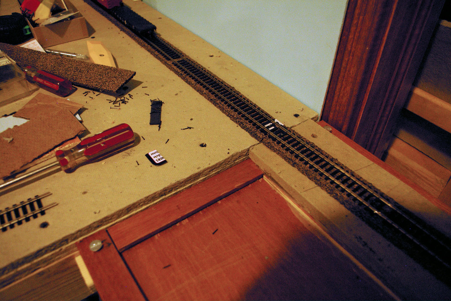
This is the gap that needed to be crossed.
I used a panel from a dressing screen. I had used the screen when I did public telescope viewing. It blocked out some of the ambient lighting. The panel is sturdy and was easy to work with.
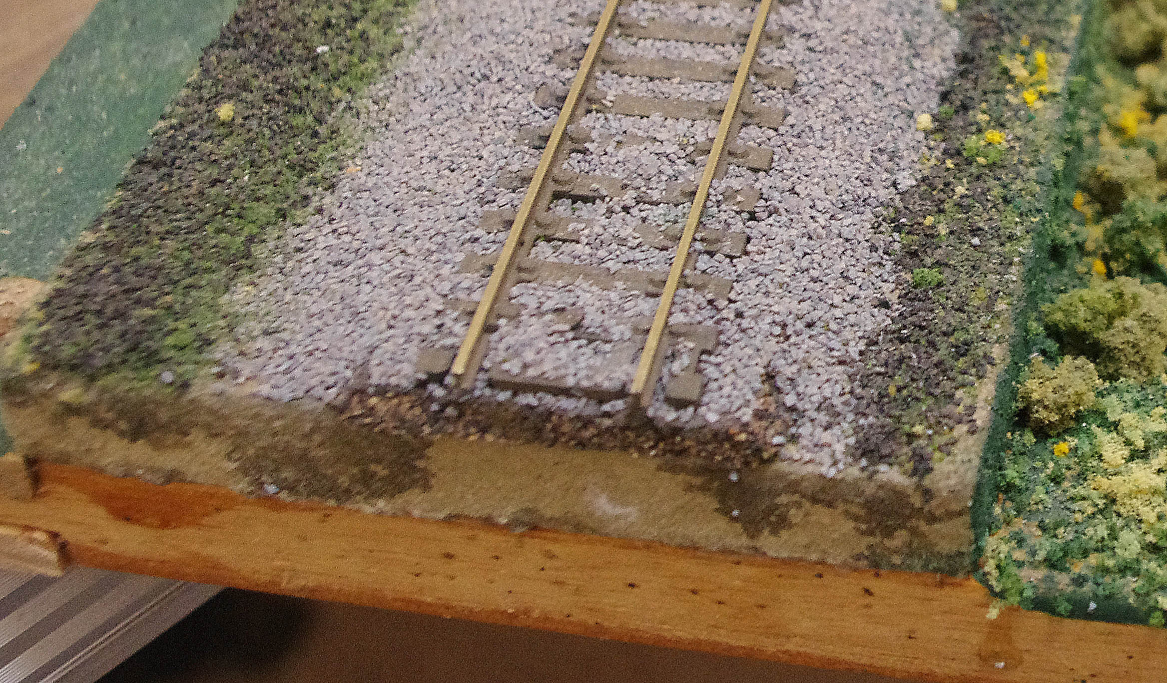
This is the finished look of the lift out. I cut the panel to the desired length that turned out to just about 3 1/2 feet long. I kept the panel the same width. This kept three sides in it’s original form. The side to the right is the cut side.
The issue of what should it look like arose. I first thought it might be a river. That would require a bridge of some sort. This is supposed to be near Boston. Walt, the owner, and I decided to make it a “fen.” He told me that a fen is a boggy or marshy area. Fenway Park was built over a fen. So, the trains are crossing a fen.
The roadbed is Homasote and cork road bed and Woodland Scenics ballast.
After carefully measuring the point of contact with the lift out I placed the track in position. It was easy on this end. The addition is Ayer and joins at Lowell Junction on the main layout. I just had to know where the joint needed to be.
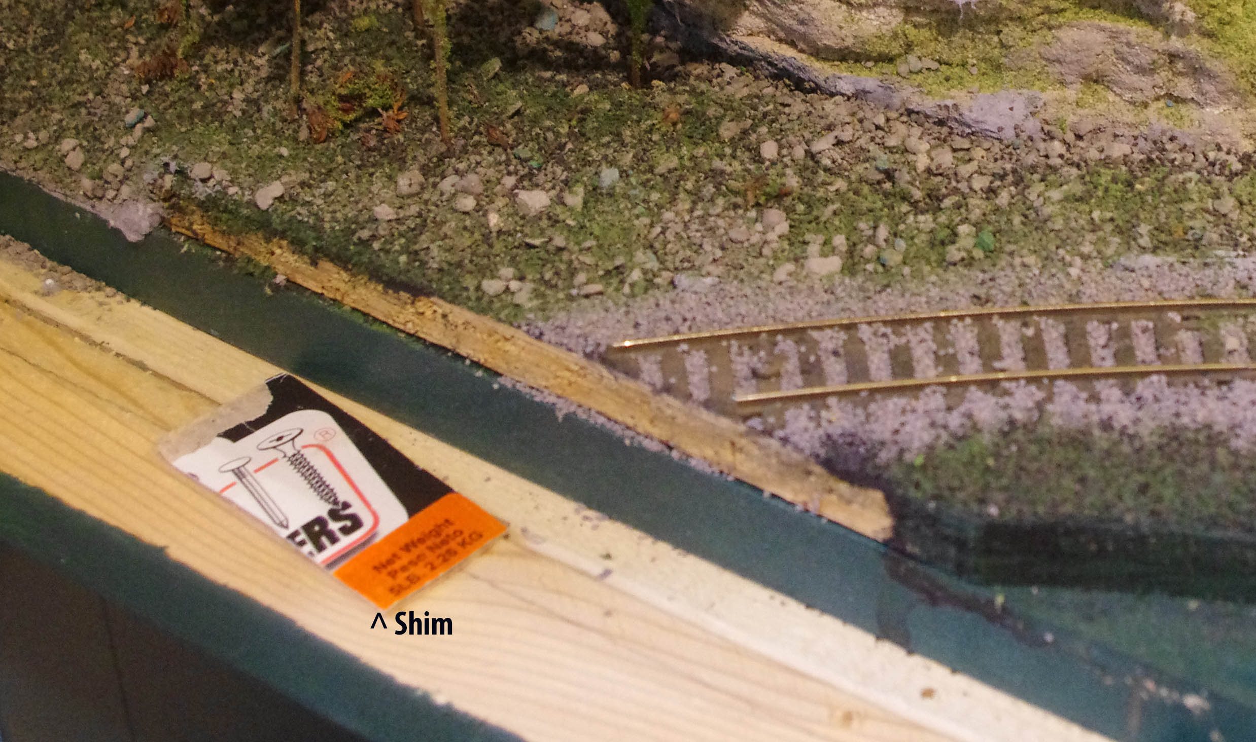
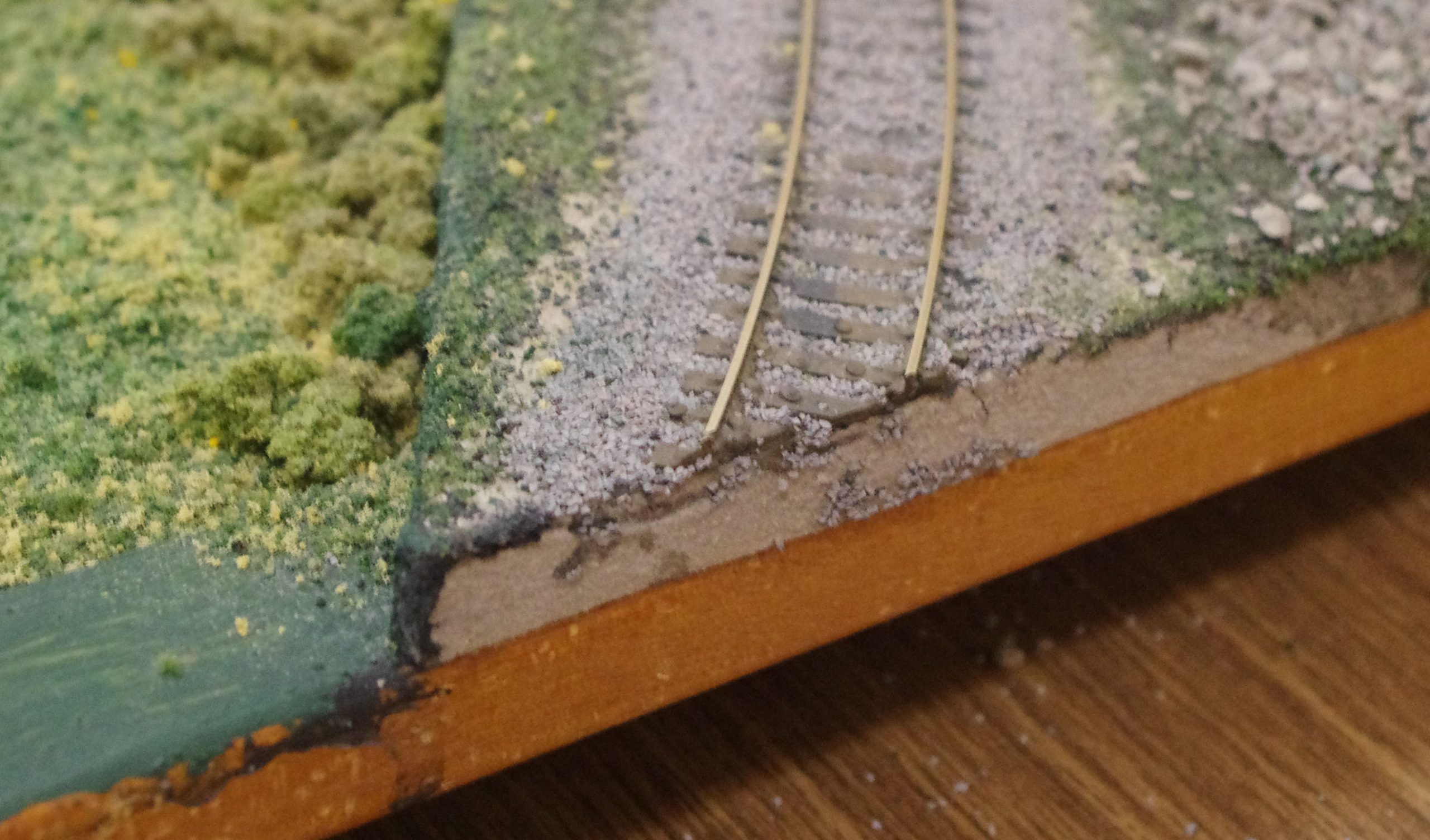
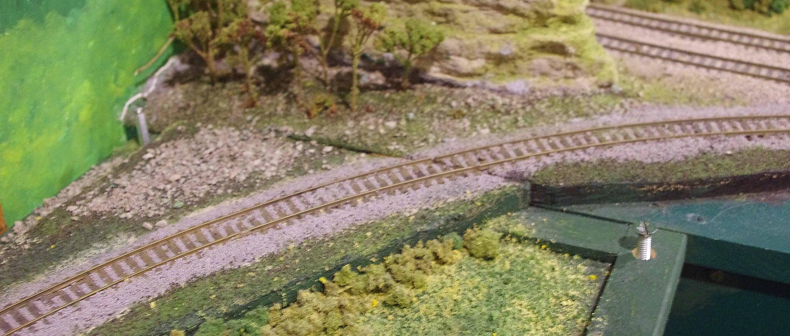
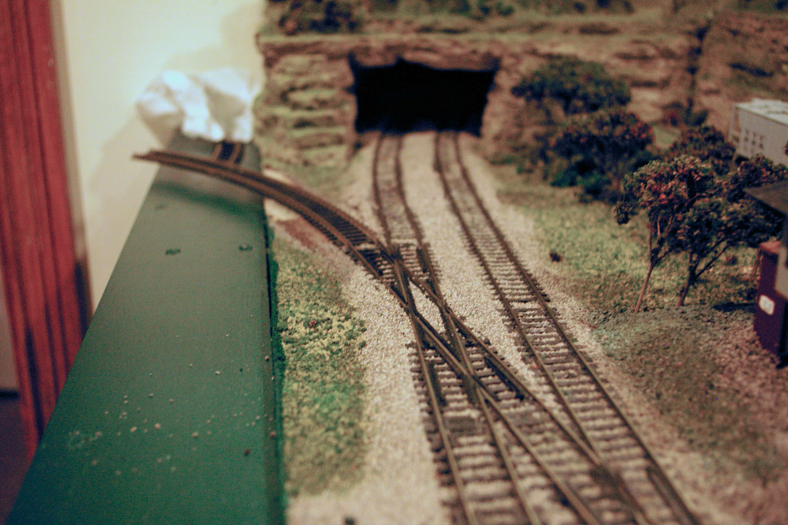
The junction end was more of a challenge. It was on a curve. Later you will see the track arrangement to the lift out. That is a very expensive shim in the photo *+) There was a slight deformation in one of the wood pieces. This was all it needed.
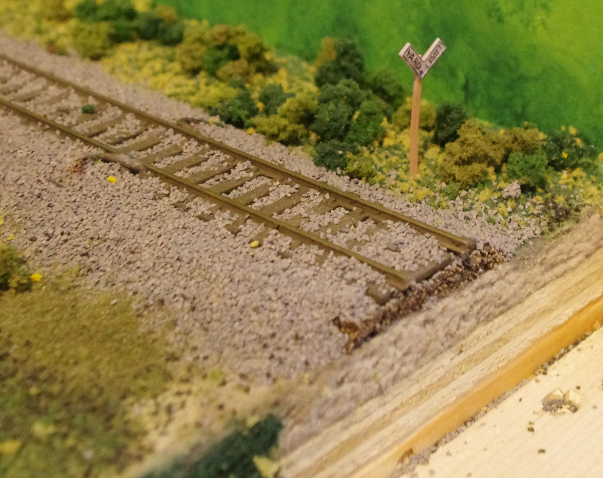
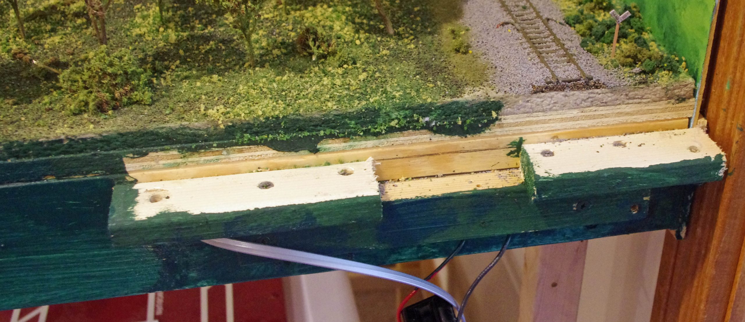
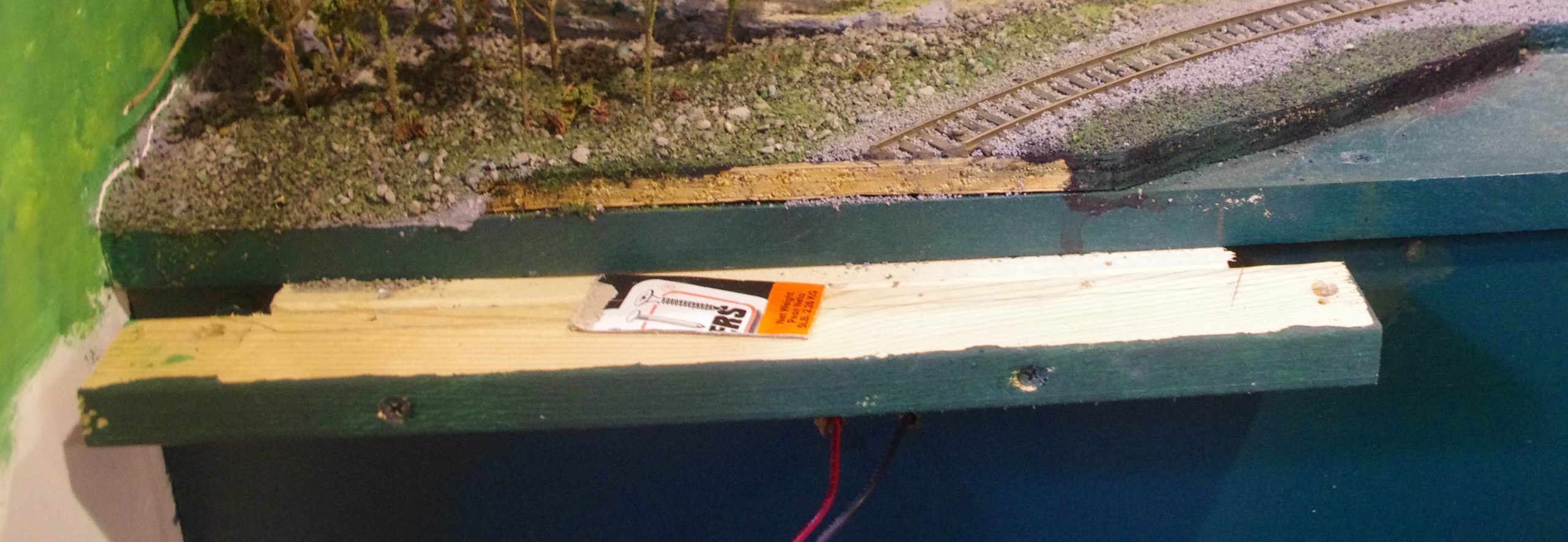
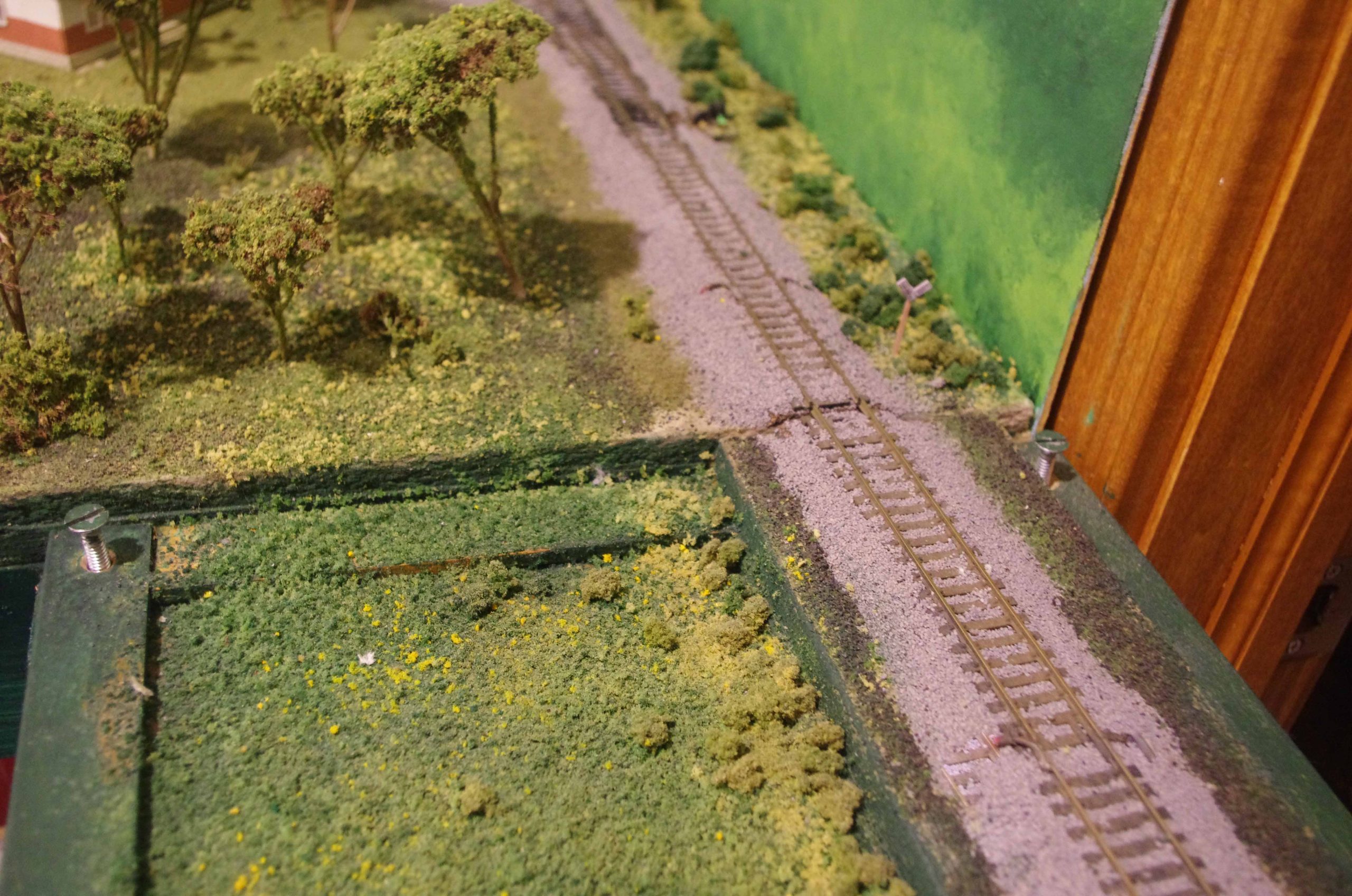
The Ayer end of the lift out.
The Lowell Junction end.
The supports for the lift out.
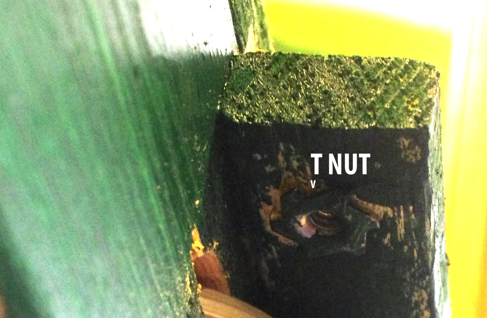
I used 3/8th inch T-Nuts for the connection points. The T-Nuts are embedded under the supports and the protruding threaded part does the aligning. Not visible is a short copper piece of tubing in each hole. This prevents any over torquing of the screw preventing distortion.
Close up of the underside showing the embedded T-Nut.
The lift out at the Lowell Junction side. The alignment screws are not tightened all the way down for this photo. These screws automatically align the track. Look carefully at the LJ end of track. You see a small screw in the center of the track. This keeps the track in place in case someone brushed up against the track. (Voice of experience learned long ago.)
Ayer side of the lift out. The screw keeping the track in place is not visible in this photo..it is there.
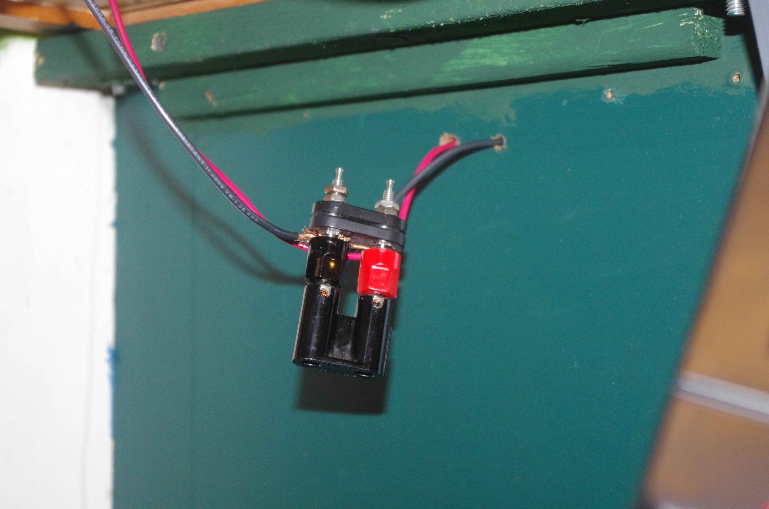
Electrical connections on both ends. These are over 80 years old. My uncle was ham operator back in the 30’s. I inherited all of his supplies. The #12 buss wires have a connector on each end and supply power to both ends and the lift out.
There is no protection for trains running off the layout. With the lift out out there is no power at Ayer. You need to throw the switch to get to Ayer and It is power routed to the lift out.
There is also a DCC connection.
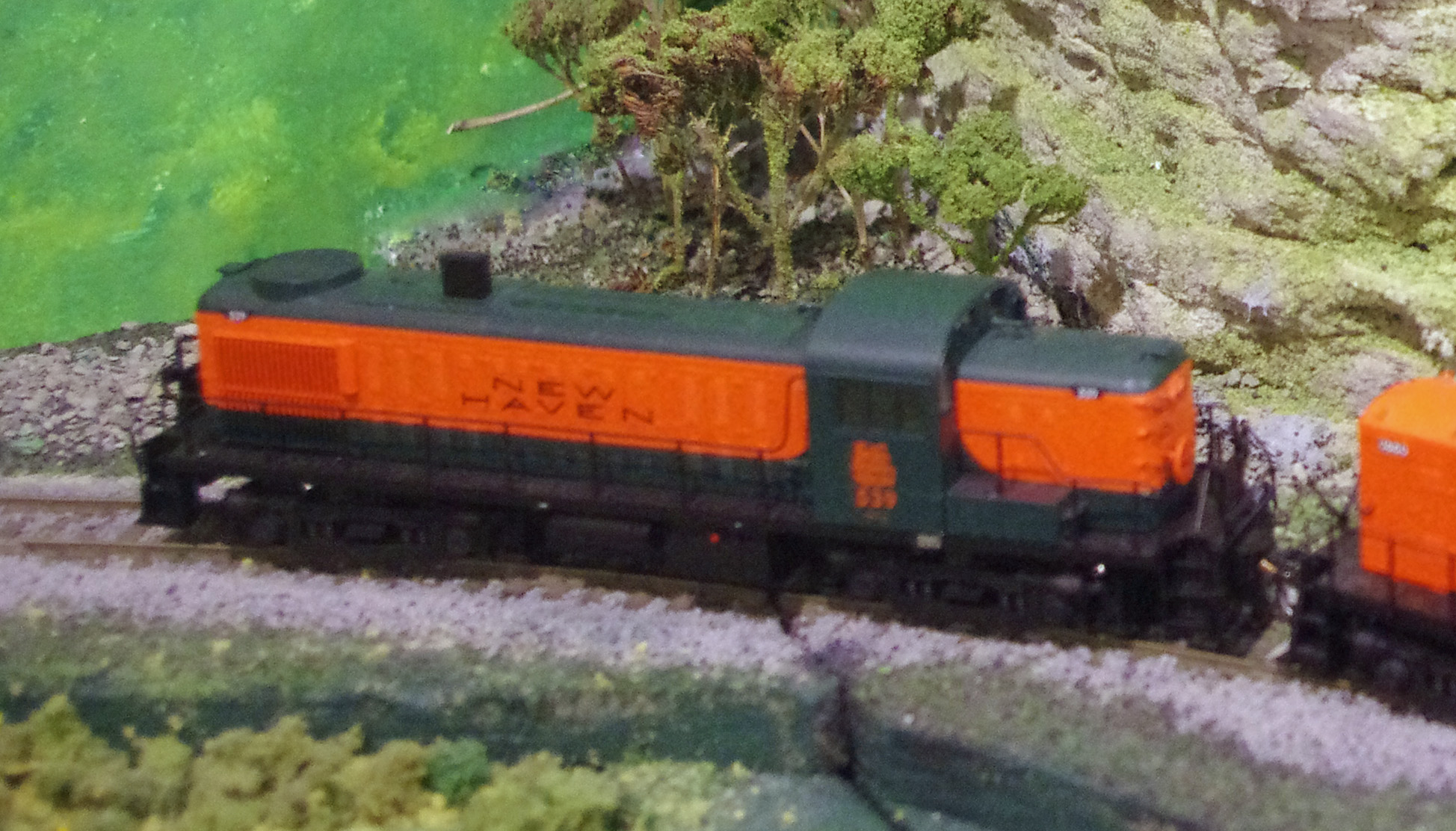
An NH train grossing the gap on the Lowell Junction side.
The Ayer addition was added after the main layout was finished. Visitors always wondered where the track was going? I had the junction in place from the beginning. This explains the easement curve in photo 4. If you were wondering why the track was not straight on the lift out and it required the curve and the possibility of derailments because of the cut in the track.
The overall junction. The NH RR uses the diamond and reaches a transfer yard. The NH RR is responsible for the upkeep of the diamond because they crossed the B&M mainline.
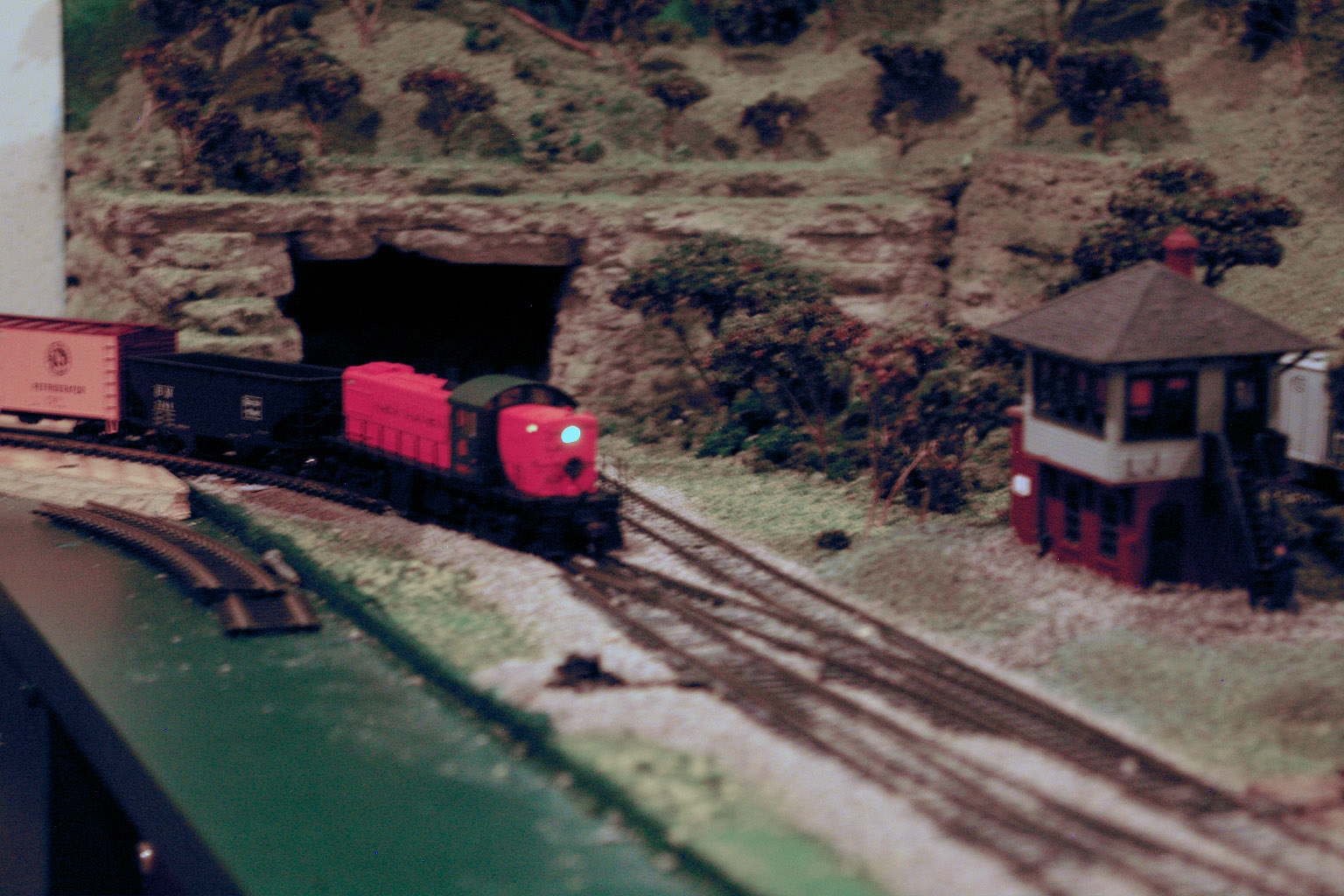
NH RR crossing the B&M heading to Lowell Junction yard.
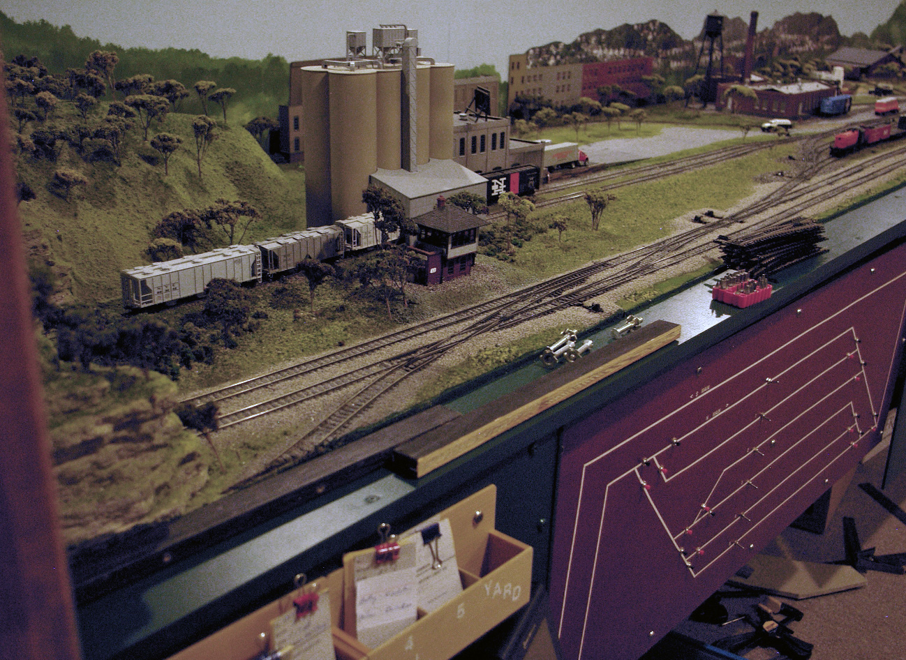
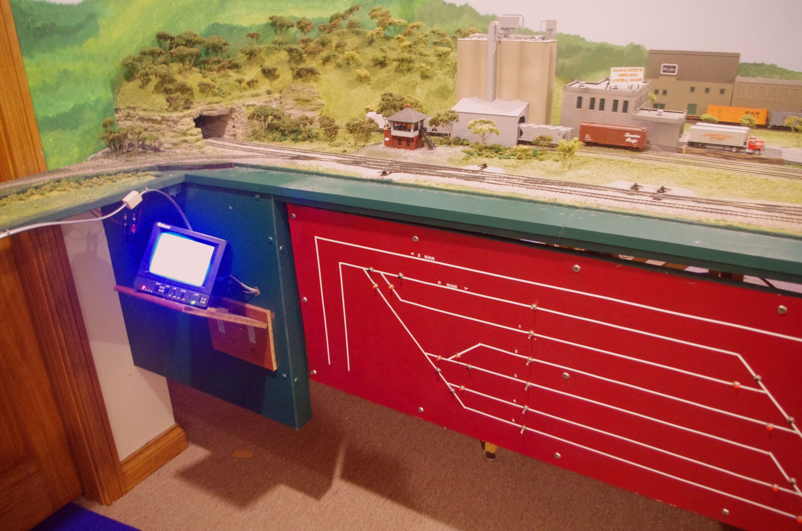
The finished look. The diagram is the lower run through and storage track at Lowell. (Not modeled.) There is a similar situation at the opposite end of the layout at Boston.(Also not modeled.)
The TV is for the 4 cameras viewing the situation in the lower level. There is also a set at Boston.
I hope this helps if you get into this situation.
Dan”
A huge big thanks to Dan for sharing his model railroad lift bridge ‘how to’.
I do love seeing what you come up with to get round the problems this hobby throws at you all.
That’s all for today folks.
Please do keep ’em coming.
And if today is the day you get started on your layout, the Beginner’s Guide is here.
Best
Al
PS Latest ebay cheat sheet is here.
PPS More HO scale train layouts here if that’s your thing.
Need buildings for your layout? Have a look at the Silly Discount bundle.




Dan, I had a similar problem on a friend’s layout. two tracks led to a station fan.
The support and track were laid across the gap. Then I installed supports under each end of the span.
The track and support were cut in appropriate places. Track was removed for this.
When this structure was removed, I removed the supports and made V cuts in each marking them accordingly. The supports and V’s were re-installed and the support structure attached to the V section. Track was relaid and shimmed to be level with the bench work sections.
Now power was supplied from the bridge portion to the lead tracks from contacts under the supports for safety .
The lead tracks were cut after the switches to the bridge. Now they could only receive power when the bridge in in place.
Additionally our wiring guru wired the bridge so the bridge could only receive power when the turnouts were set for the beige.
To keep the guru free of migraines, traffic is only in one direction across the bridge.
I was interested in seeing this today because I’m facing the same dilemma… for me I had the option of the lift out section on tangent track – but it is a 3 track main line … there is always something challenging about the location where a lift out is required it seems –
I’m working to utilize one of these Adjustable Electric Stand Up Desks with a Single Motor I’ll let you k on how it goes
Dan, Your solution is simple and workable. I like the old connector. Having one track join on a curve did make the geometry a little more critical, but the blocking looks like it solved the positioning well. Yours looks like a good operating layout. Rob
good problem solving. use as much space as you can, even if you go across a doorway, love it.