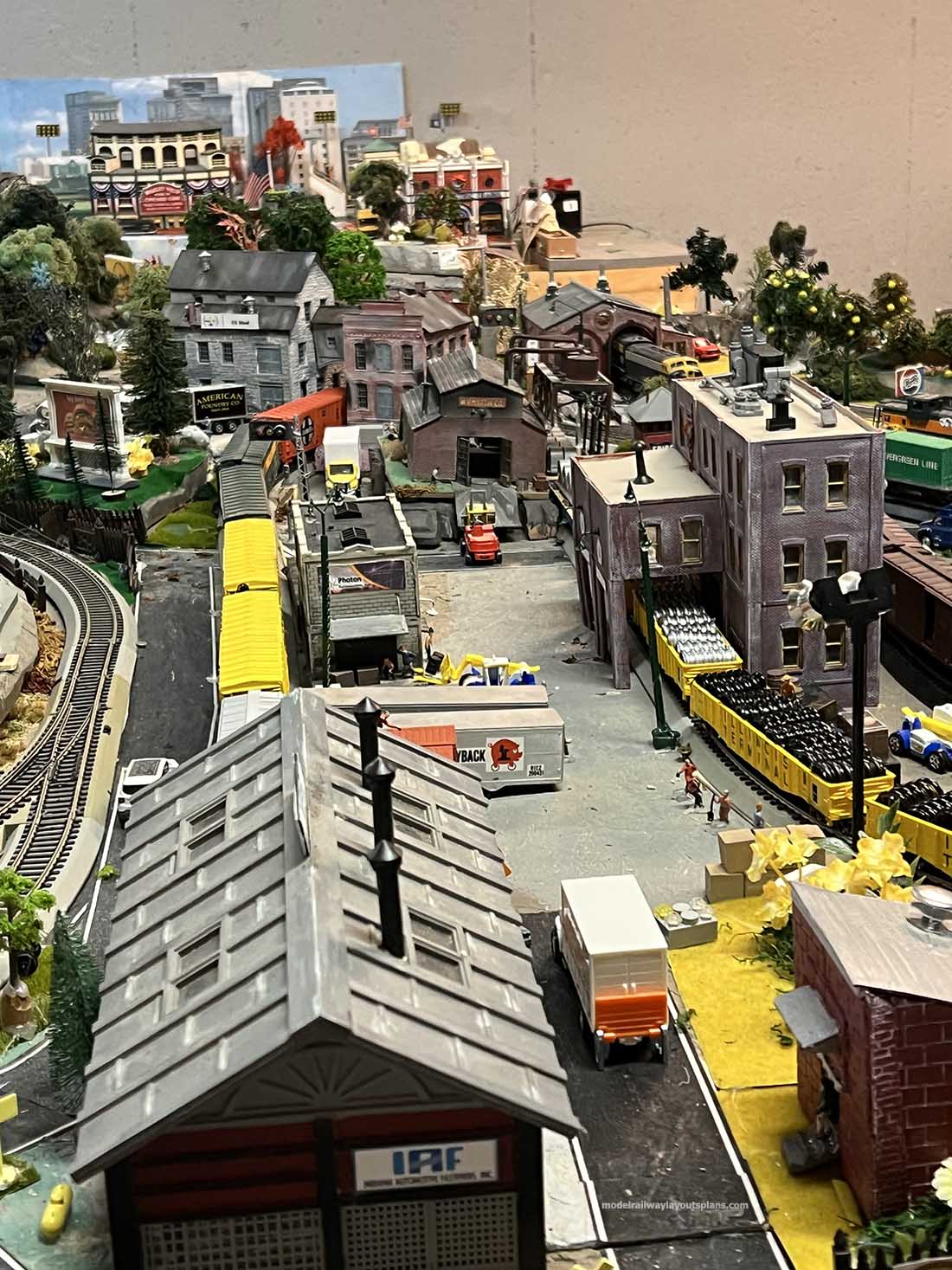
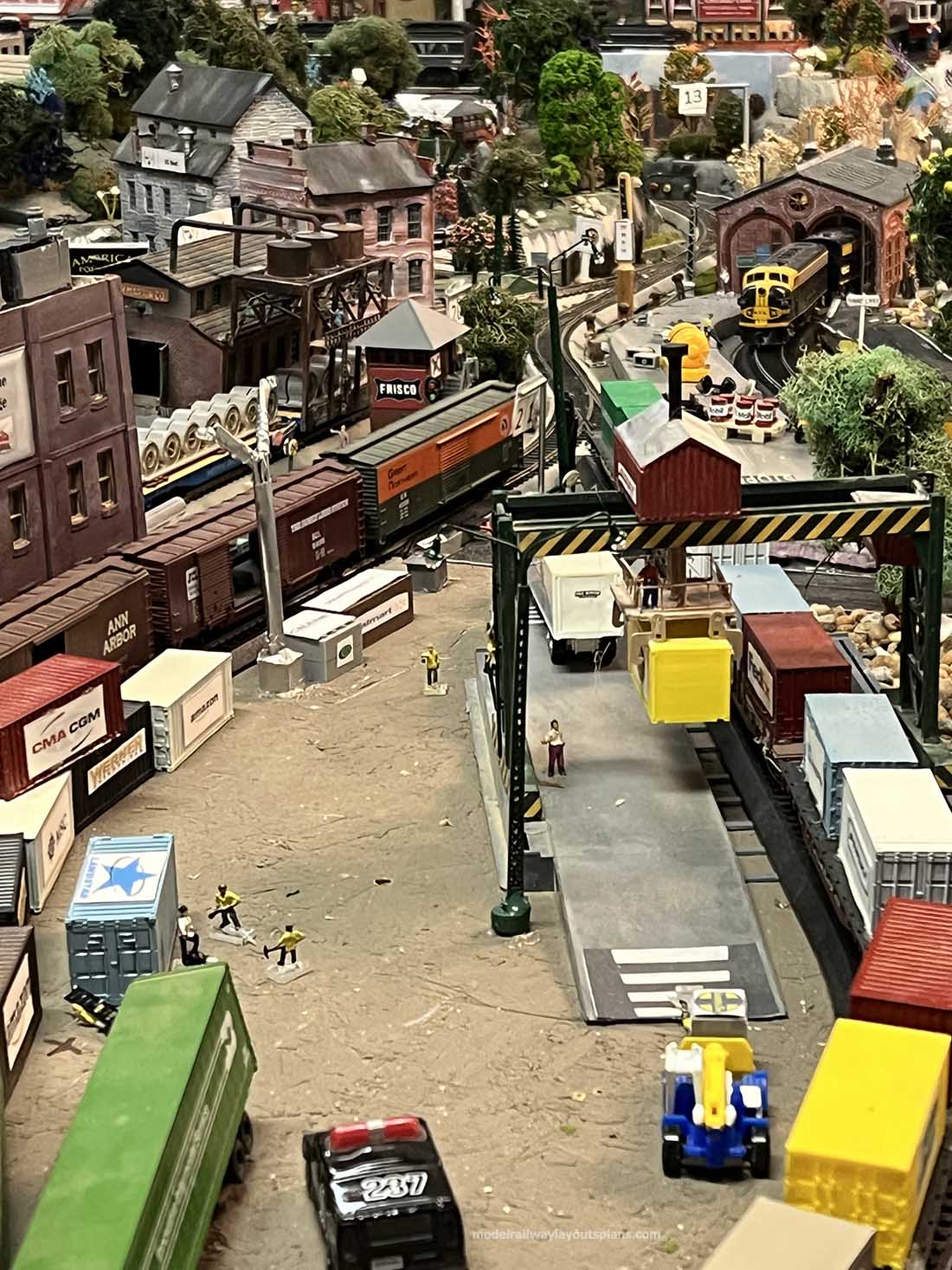
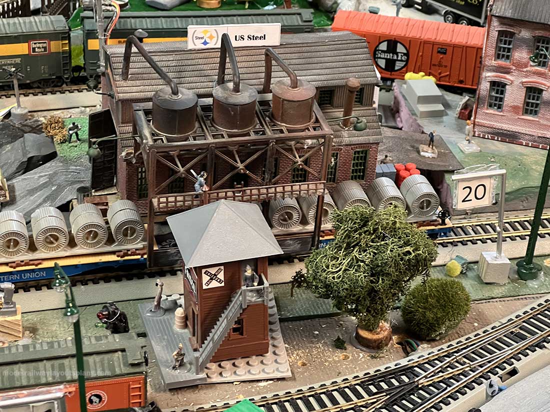
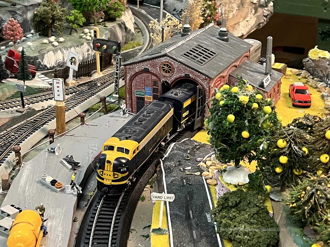
The talented Ken has been back in touch with his HO scale switch rebuild:
“Hey Al,
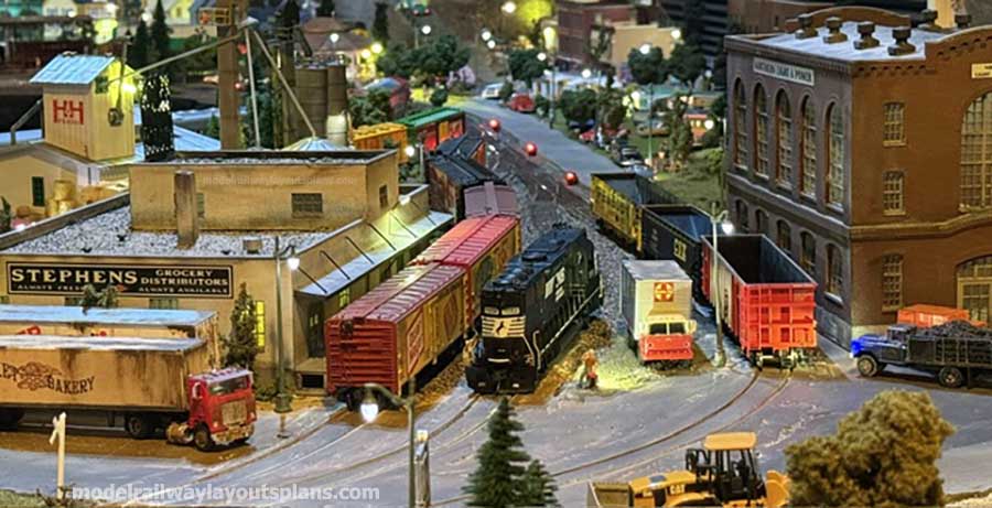
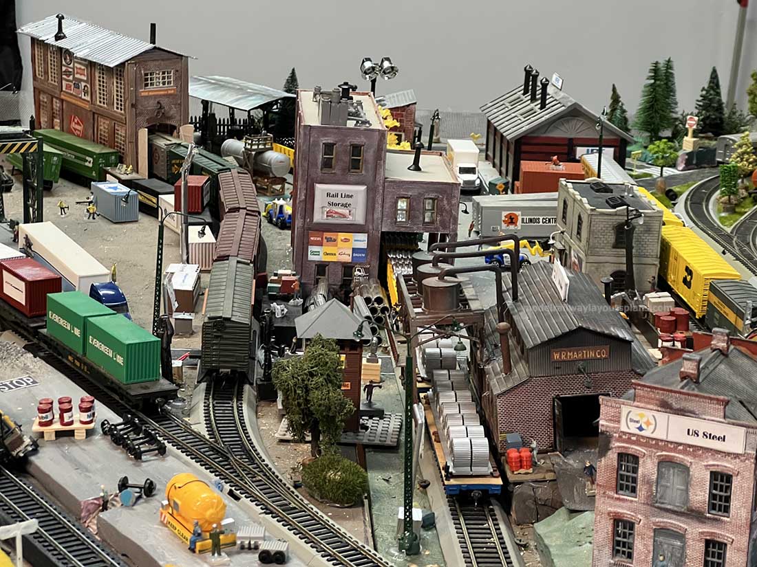
It’s been about a year since my last update. I really thought I was done with my layout, but there was something bugging me about how the (3) industries on my industrial section were laid out.
The only way to spot cars into these industries was to back in and drop them off.
That created a problem in that if I had 3 coal hoppers backed into the power plant, how would I get the front and middle hopper unloaded. Same thing with the wholesale grocery supplier as well as the feed mill.
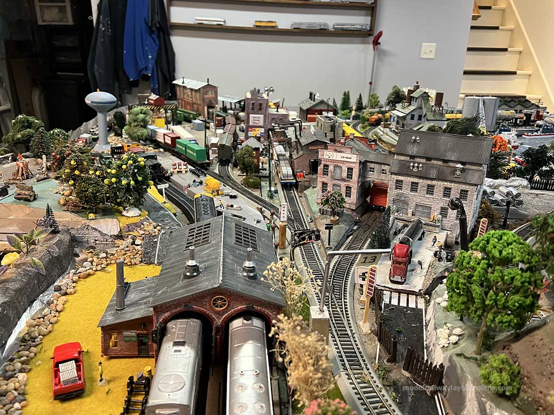
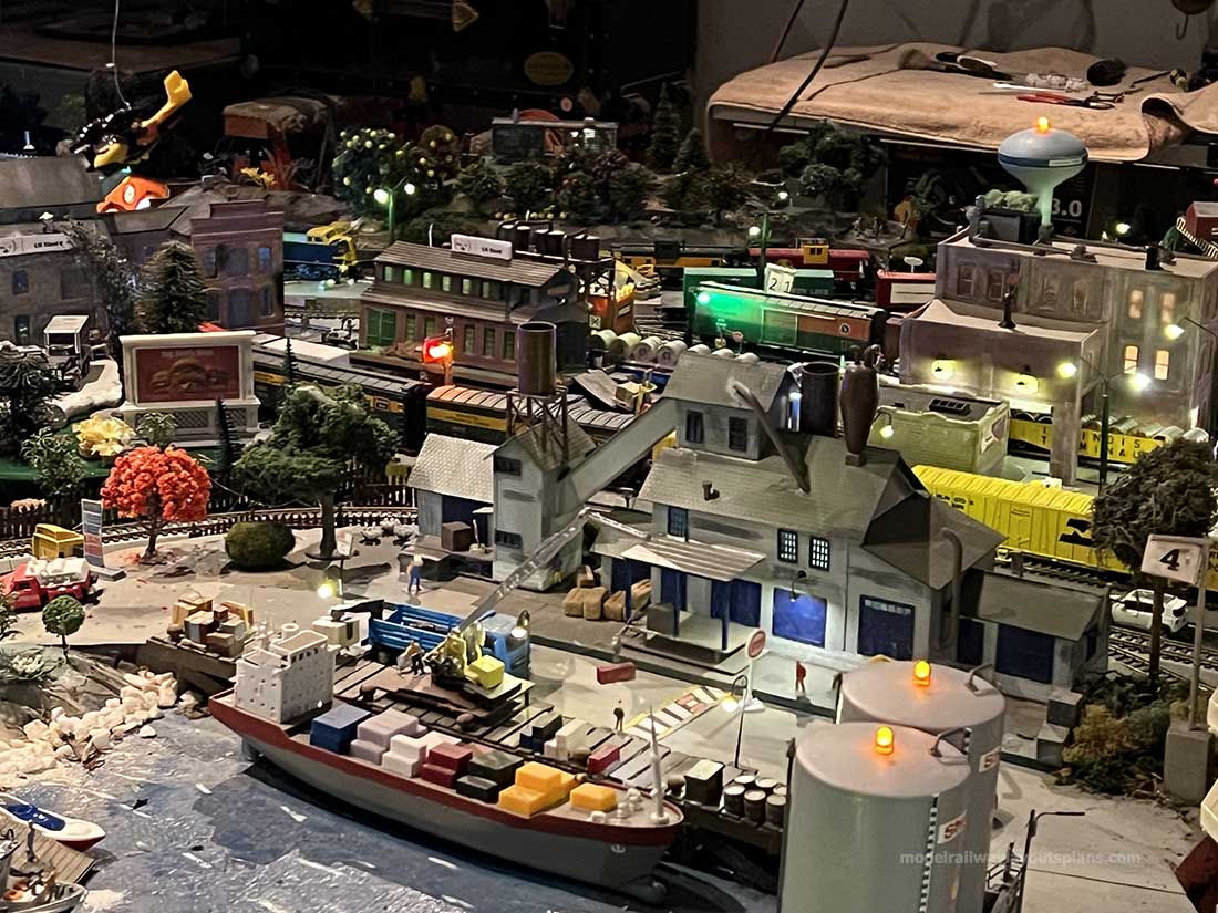
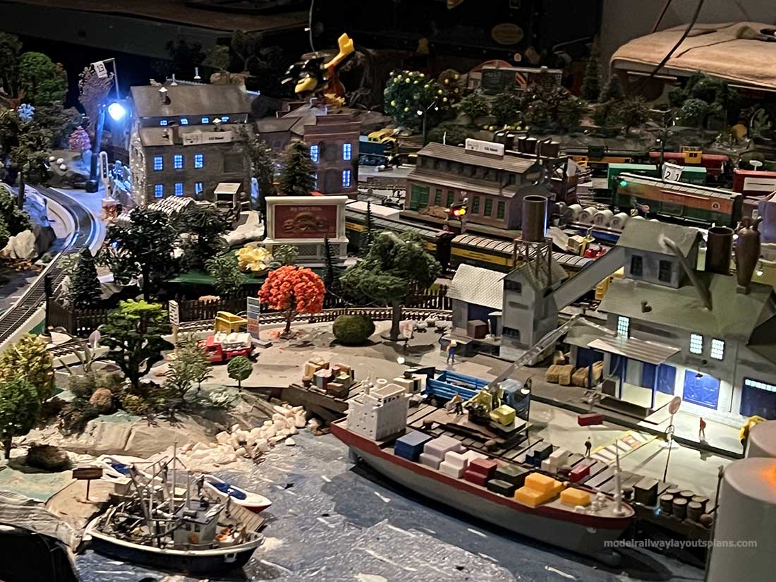
So, I decided to extend the layout out so I could bring the locos in from the back side and drop them off that way.
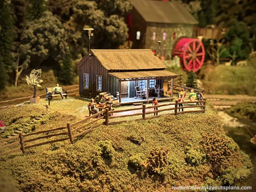
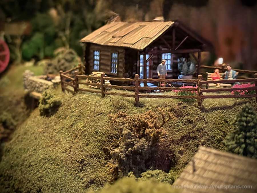
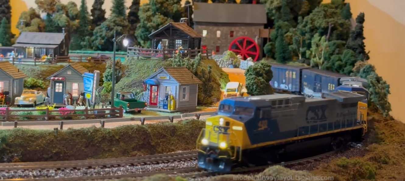
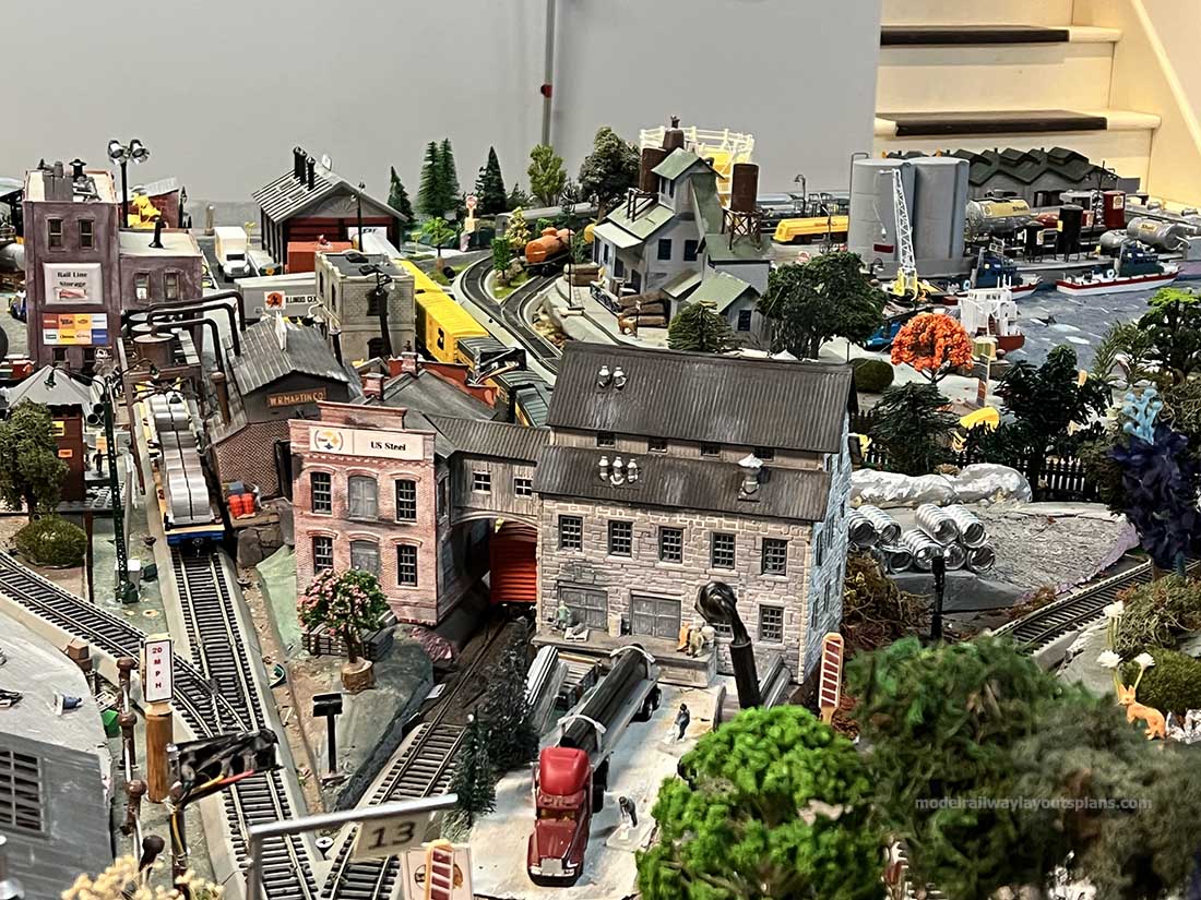
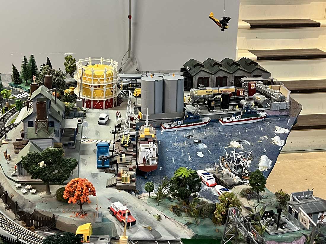
Plus I created a run-around track to give me switching opportunities. I always wanted to have a grist mill on my layout, but there wasn’t enough room. By creating this extension it opened up the opportunity to build a mill pond along with a grist mill.
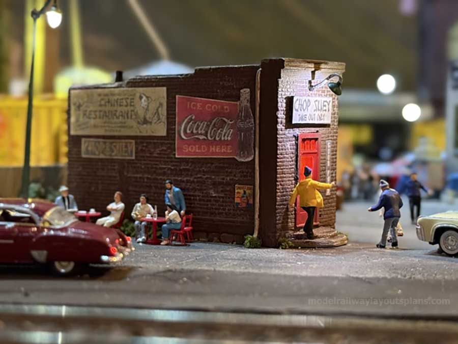
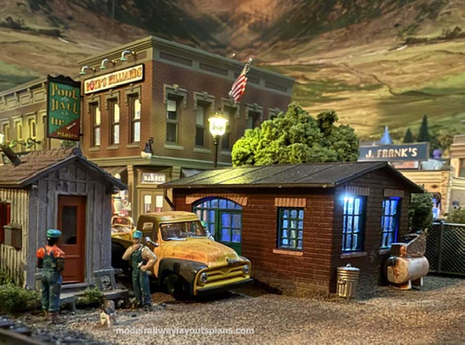
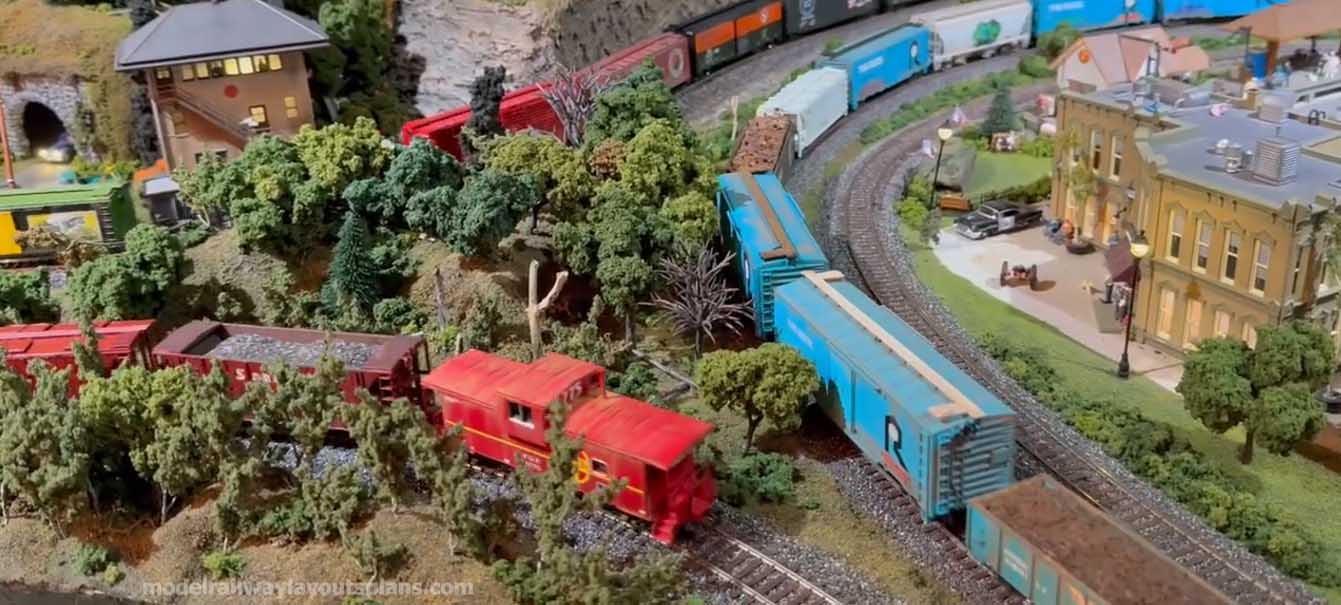
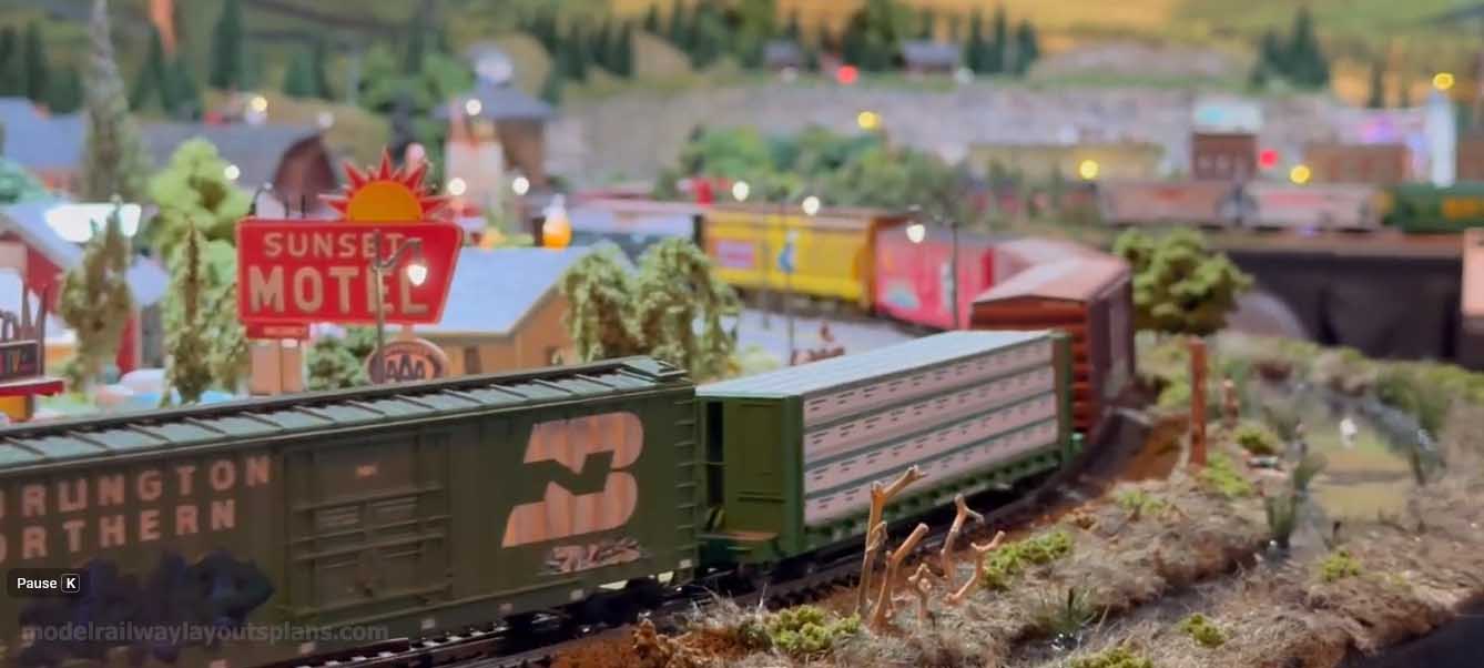
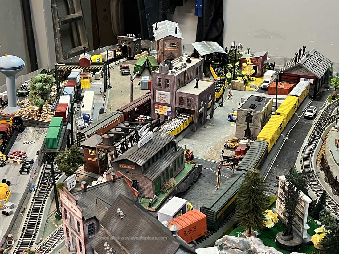
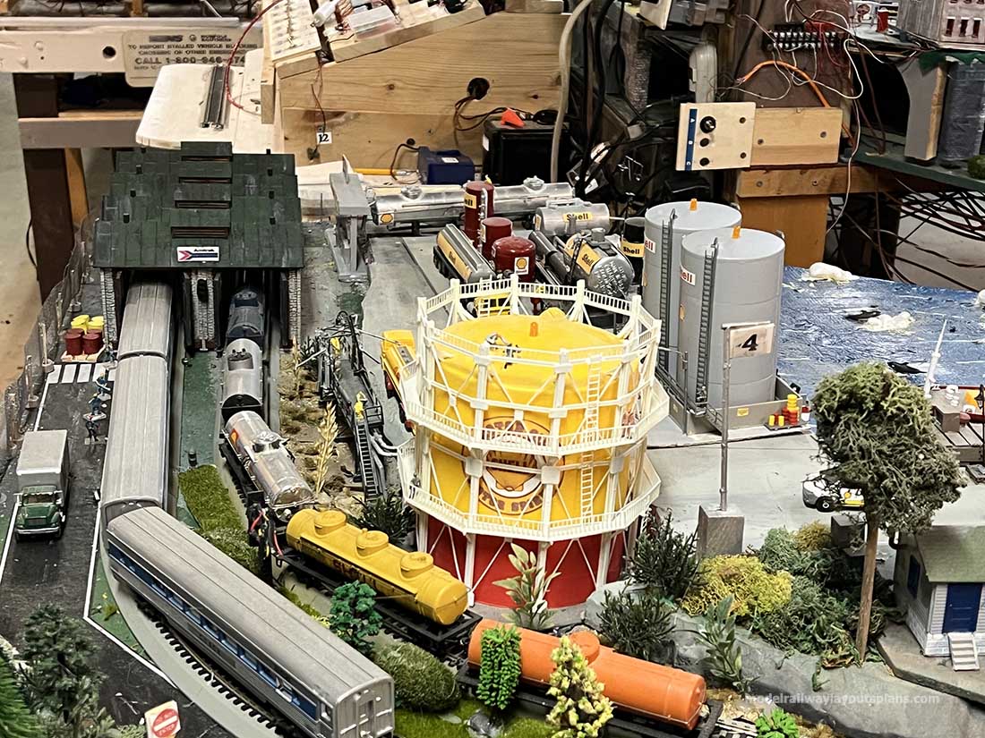
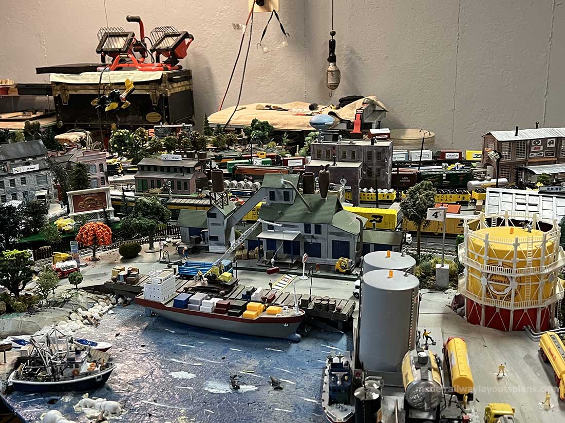
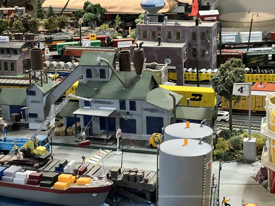
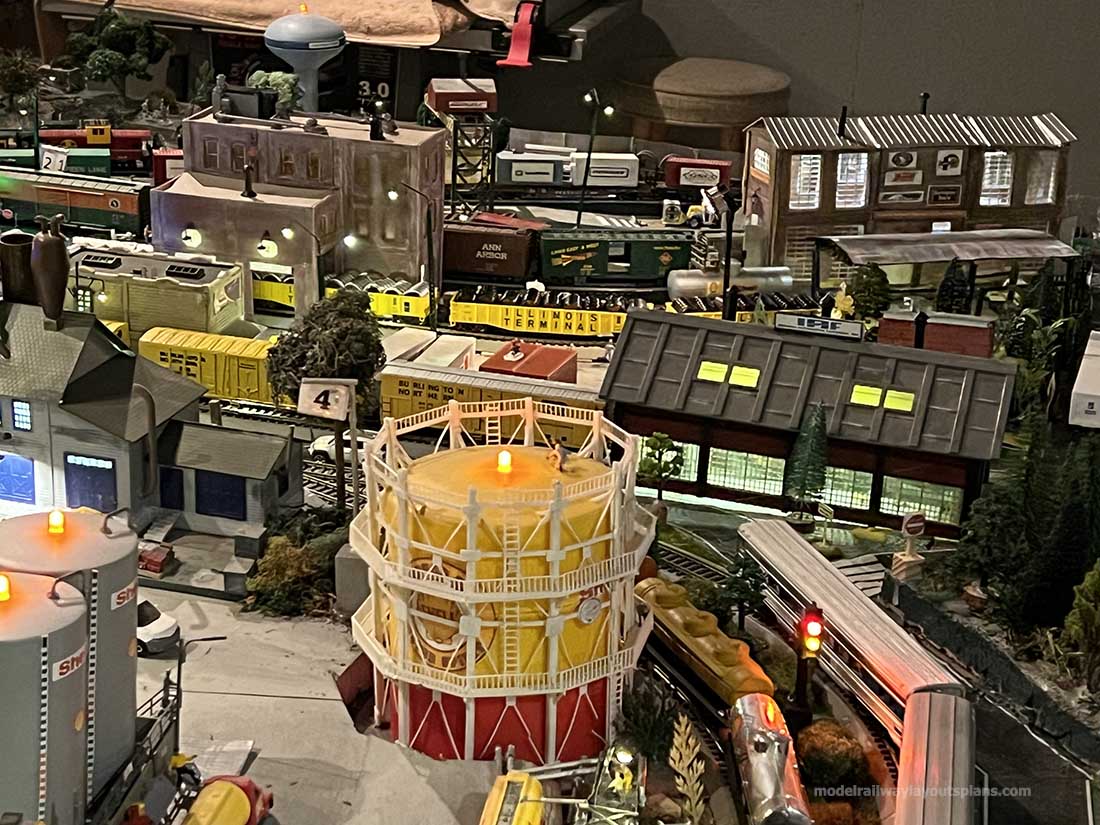
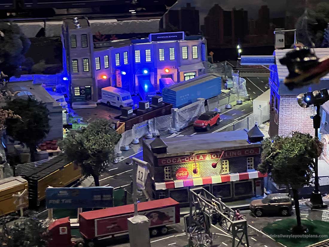
I’ve posted a couple pics here but I’m also posting a link to a YouTube video of my layout showing several trains running. It is a compilation style. Please forgive me for its length, it’s 23 minutes long.
So if you have time in the morning having your coffee or tea please check it out and give me a like if you would. No narration, just trains and photos. Thanks a bunch.
Ken”

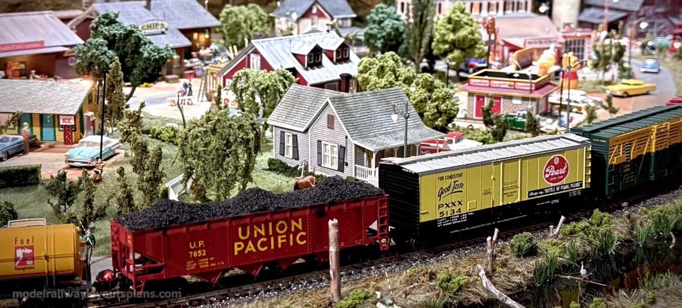
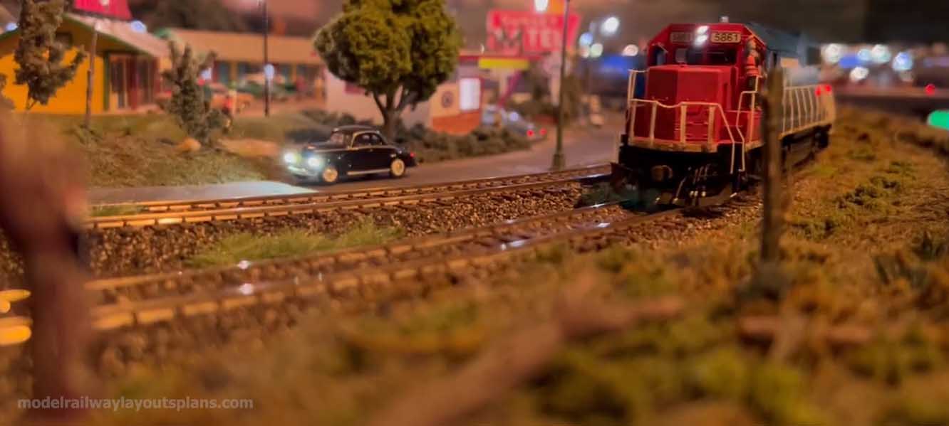
A huge big thanks to Ken for sharing his HO scale switch rebuild. What a layout!
You can see Ken’s last post here: HO scale layout plans
That’s all for this time folks.
Please do keep ’em coming.
Is today the day when you make your big start?the Beginner’s Guide is here.
Remember, it’s the start the stops most people…
Best
Al
PS More HO scale train layouts here if that’s your thing.
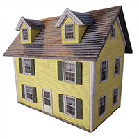 The Smith’s house – yellow
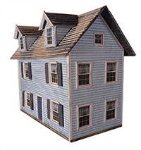 The Miller’s house – blue
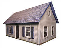 The Johnson’s house – gray
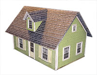 The Davis’s house – green
 Smokey Joe’s lock up
 Carl’s brick store
 Fat Bob’s store house
 Big Tom’s timber store
 Big Kahuna bundle deal
 Silly discount bundle