Bruce been in touch with a very helpful post on building model train inclines.
Here’s a thorny issue that comes up quite a lot in my inbox.
Now on to Bruce and his piece on building model train inclines.
(His curve clearance post is here.)
“Al,
Some time ago, I sent a graphic with explanation on selecting the minimum radius for two parallel sets of rails. Some appreciative comments were added.
I have noted that in several viewer responses that there may be some difficulty determining rail length for various %slopes.
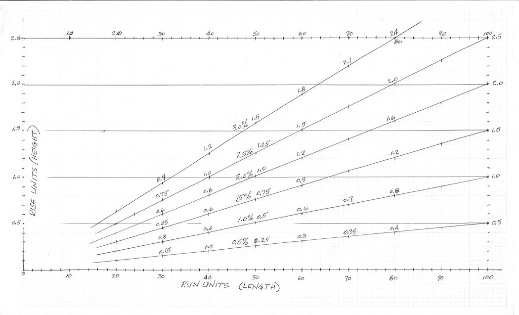
I thought perhaps that some users might have an easier solution by using a graph. Therefore, I am providing the following with example of usage for building a model train incline.
Rise and Run
%slope (percent slope) is determined by using the formula
RISE X 100 = %slope
RUN
The graph is graduated in UNITs. One unit may be any length measure base.
This would be determined by the measure the user decides to use; mm (millimeters), cm (centimeters) or inches.
Of course one could use Yards, Miles, Light Years or any other.
On the graph are lines representing typical %slopes plotted for determining either RISE or RUN.
Or, knowing the RISE and RUN, the %slope may be found.
Assume the user is into HO scale. Then on both the vertical (RISE) and horizontal (RUN), the Unit 1, 2, 50, 100, etc, might be labeled as cm (centimeters).
First one must determine the minimum height to be used for clearances of one track over or under another.
Select the tallest Locomotive or Car and measure its height in the cm.
Add additional measure for assurance of clearance.
I.e., tallest item might be 5.0 cm.
Then add to this using this measure, the height of roadbed and rails; 0.5 cm is assumed for example.
Then 5.5 cm would represent the minimum amount of RISE to be used with the desired %slope to determine the amount of RUN required.
Now one can determine whether he has enough real estate to accomplish the desired %slope.
Example referring to the accompanying graph.
Note that the RISE graph values range from 0 – 2.0 and the RUN values range from 0 – 100 UNITs.
Note also that the graph is linear for both RISE and RUN.
Minimum clearance height of 5.5 cm. This value is then equal to 1 UNIT on both RISE and RUN.
Example #1: Determine amount of RISE for given RUN and any %slope.
Select the desired RUN based of available real estate.
Assume RUN available to be 440 cm.
440 cm divided by 5.5 cm equals 80 UNITs.
Assume maximum clearance RISE allowed to be 11 cm or 2 UNITs.
Then search RISE value for each crossing value on the %slope values vertical to the 80 cm RUN value.
For this example, the 1.5 %slope provides a 1.2 UNIT RISE for the 80 UNIT RUN., or 5.5 X 1.2 = 6.6 cm minimum.
Also, using the 80 UNITs RUN, find the %slope value using the 11 cm RISE line. The crossing is found to be the 2.5 %slope line. One might consider this to be the steepest grade for his train to successfully climb with a desired number of cars coupled.
Example #2, the 3 %slope is desired for the 80 UNIT RUN. Find the required RISE (height) for this %slope.
The graph is linear; thus, the 3 %slope RISE would equal 2 X 1.5% RISE = 2.4 UNIT RISE or 2.4 UNITs X 5.5 cm = 13.2 cm.
Example #2: Determine amount of RUN for given RISE and SLOPE.
Assume RISE = 1.2 UNITs and SLOPE = 2%.
Search the 1.2 UNIT RISE value horizontal to the intersection of the 2% SLOPE line.
The RUN would be down from this intersect to the value of 60 UNITs.
The amount real estate required would be 60 UNIT RUN X 5.5 cm = 330 cm.
In like manner, one could determine %sLOPE by locating the intersect of the given RISE versus the given RUN.
Of course not all measurements will coincide with any graph interest, but the use can then eyeball the desired value between any two intersects.
Al, I certainly hope this is of value to your viewers. I certainly, enjoy all the posts and comments. I also have gained some insight from many of the posts as I continue my future layout. I have a lot of work ahead. Many comments have assisted to reduce some of the work load.
Bruce”
A big thanks to Bruce – it reminded me of Chris’s post: How to make inclines.
And Dean’s: Model train inclines.
Now on to Bob – he sent me this in but it fell through the cracks.
Fortunatley he gave me a gentle prompt, and I’m glad he did too, I enjoyed his vid.
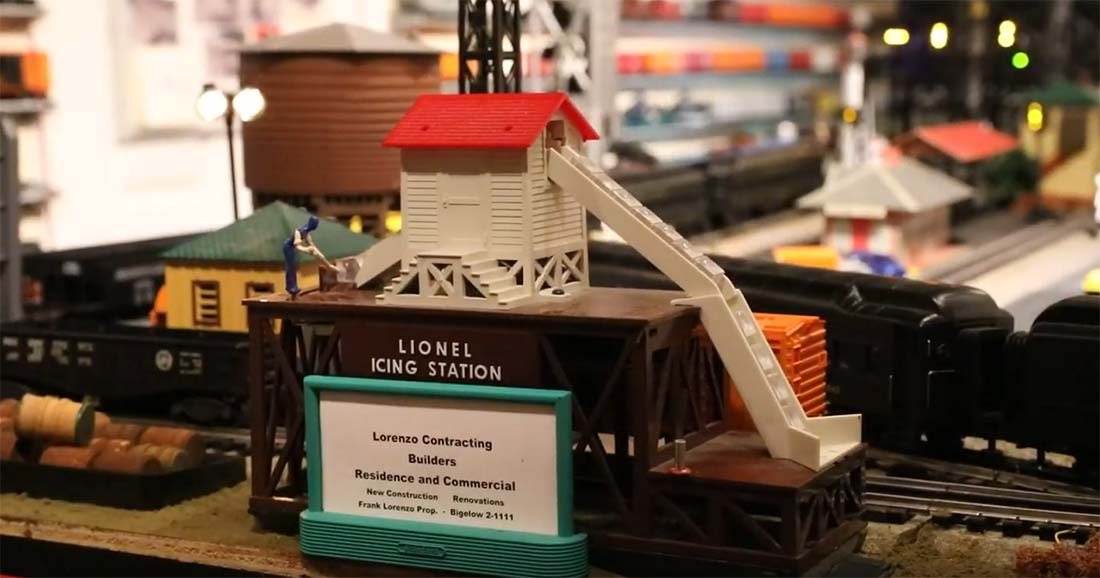
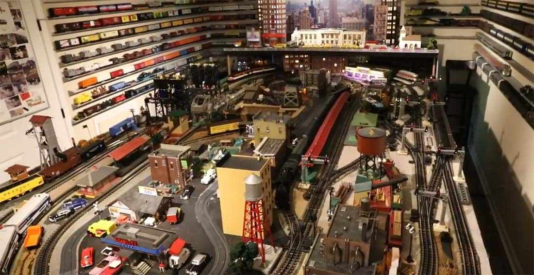
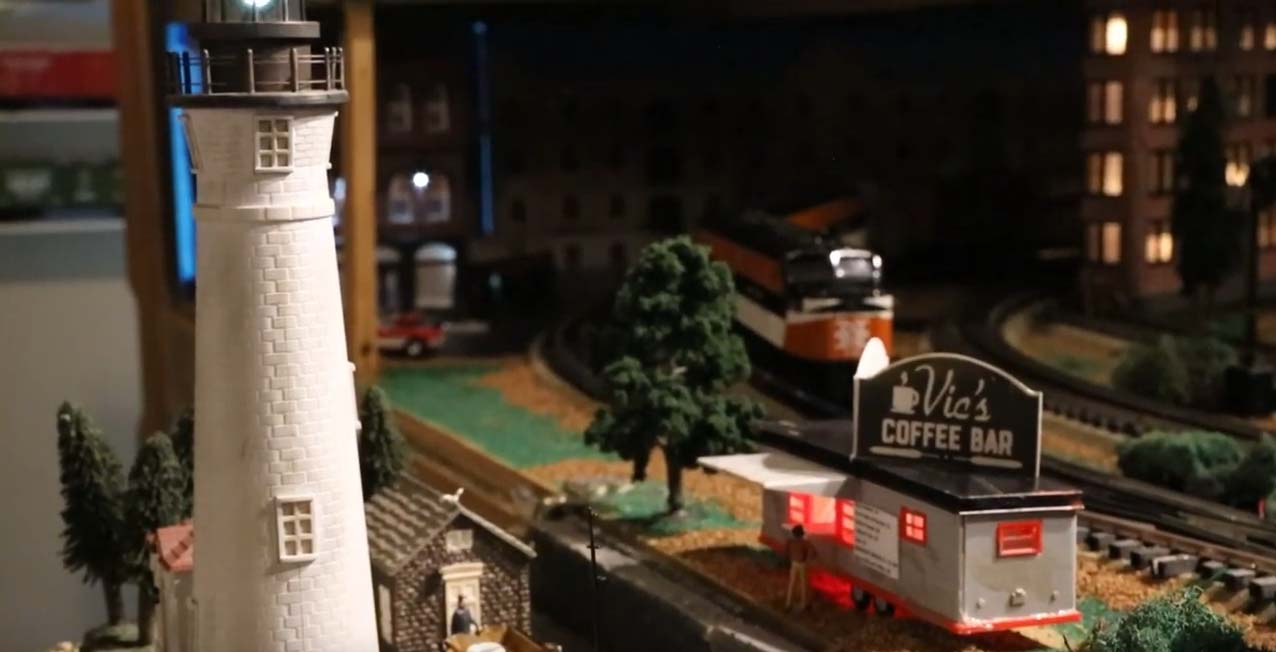
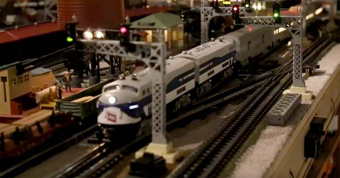
“Al,
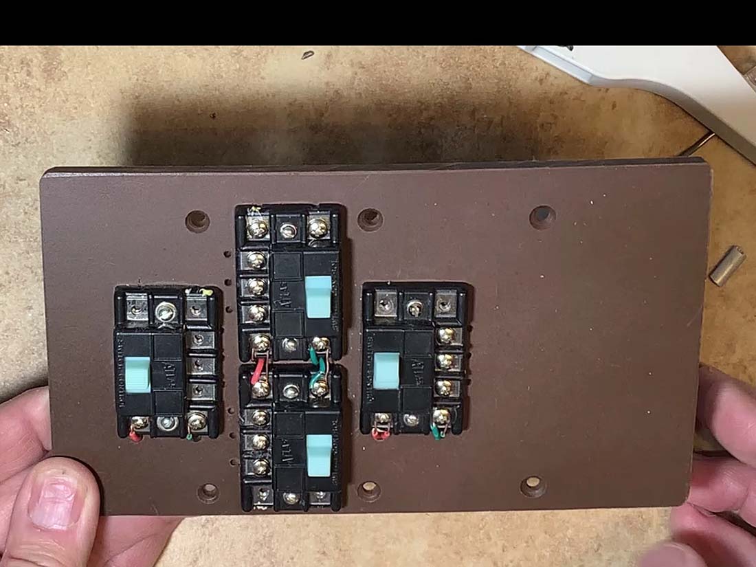
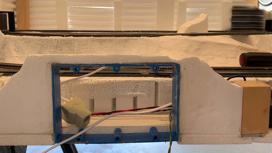
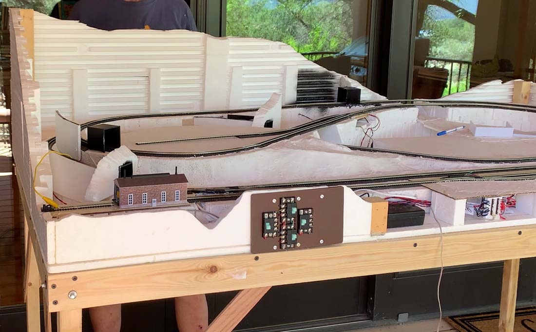
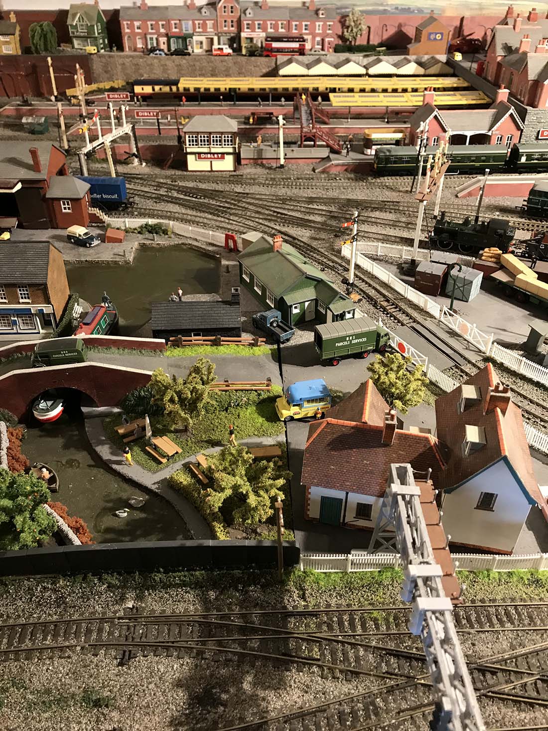
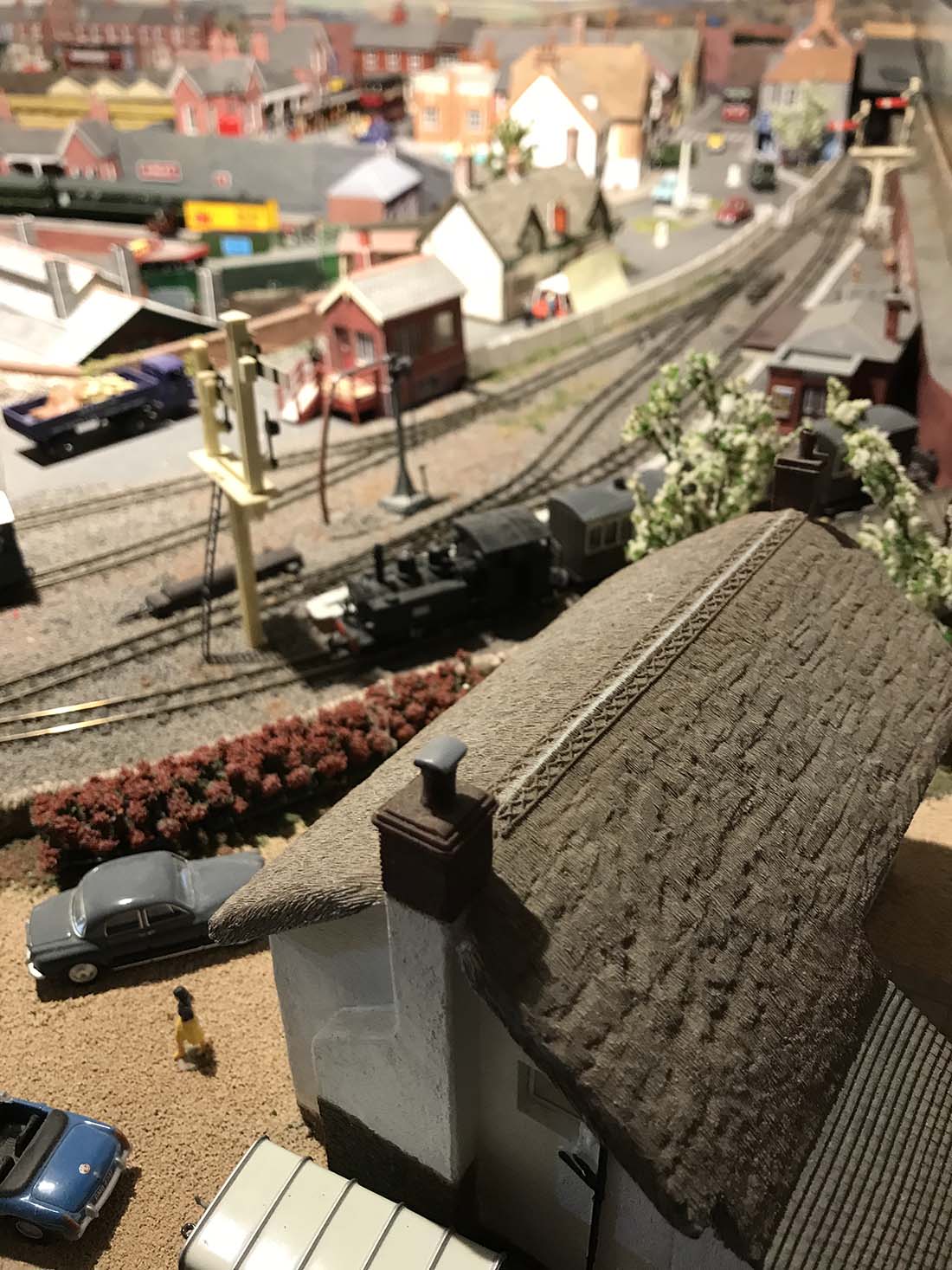
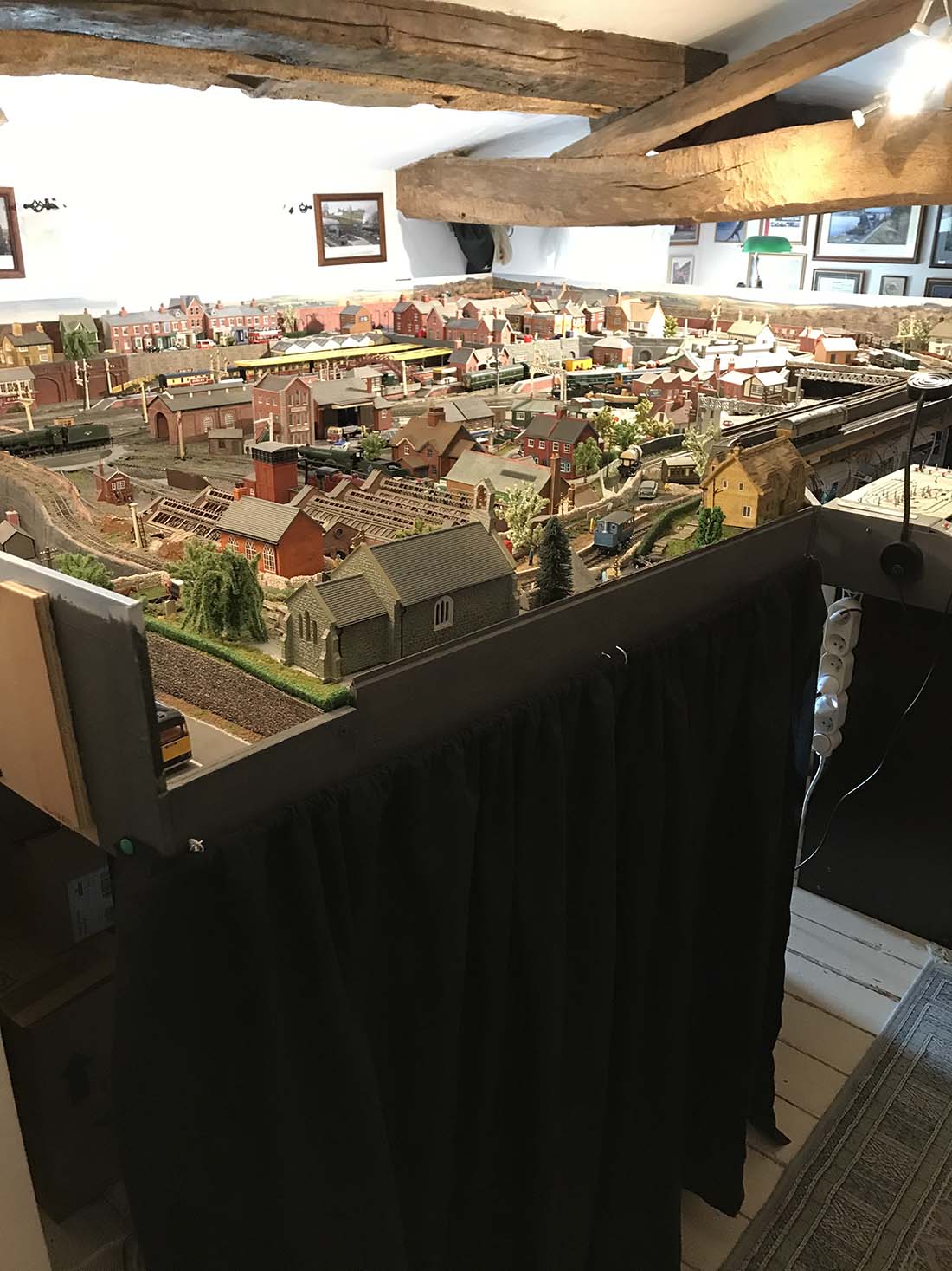
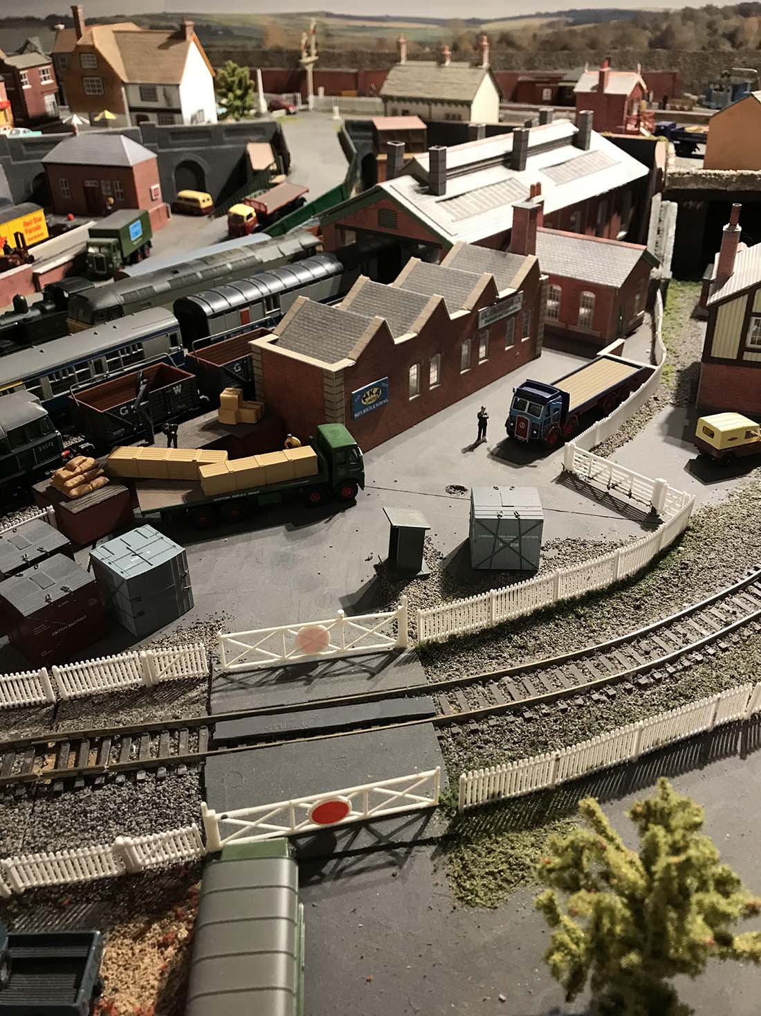
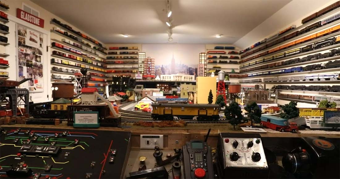
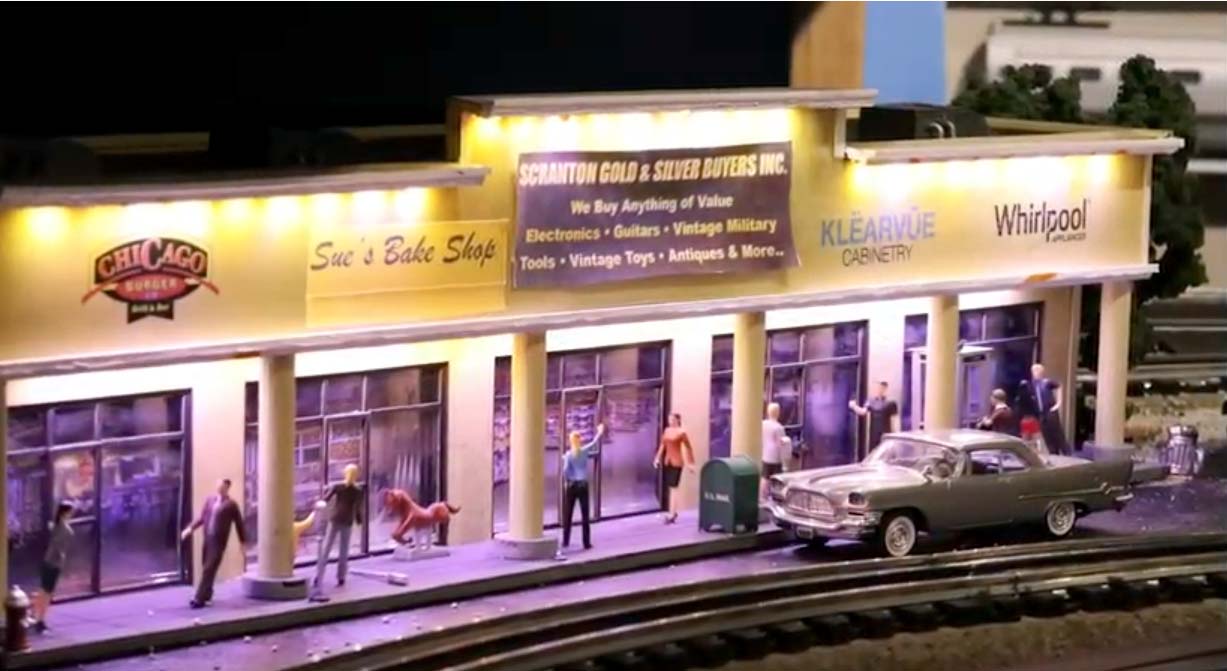
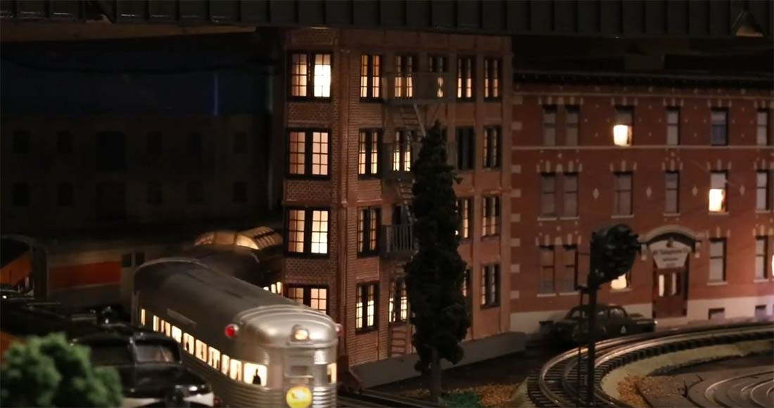
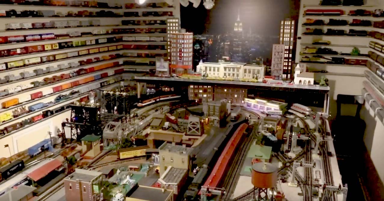
Thanks for all your emails, I find them quite inspiring. This video explains all the features of my layout.
Regards,
Bob”


A huge thanks to Bruce and Bob. What a clever lot you all are.
And if you like this tip, don’t forget the Beginner’s Guide is jam packed with more just like it.
That’s all this time folks.
Please do keep ’em coming.
Best
Al
PS Have you had a look at the new ebay cheat sheet yet?