Rich has been back in touch with some very impressive N scale girder bridge pics.
“Hi Al.
I know its been a while since my last post. From time to time life gets in the way of our hobby.
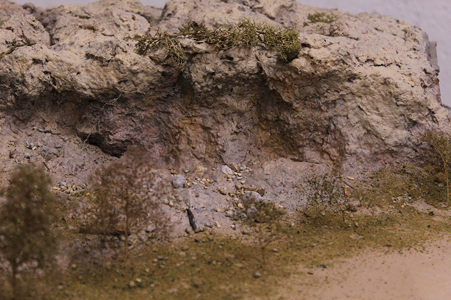
Through what I have learned on your web site [ I read all your posts. ] I believe I have done well on my side cliff coloration blend.
Still working on many other areas of my lay out and loving every time I get the chance to work on it.
Thanks again Al for all your posts.
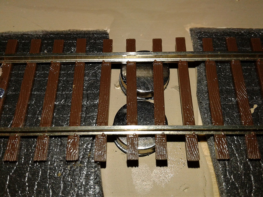
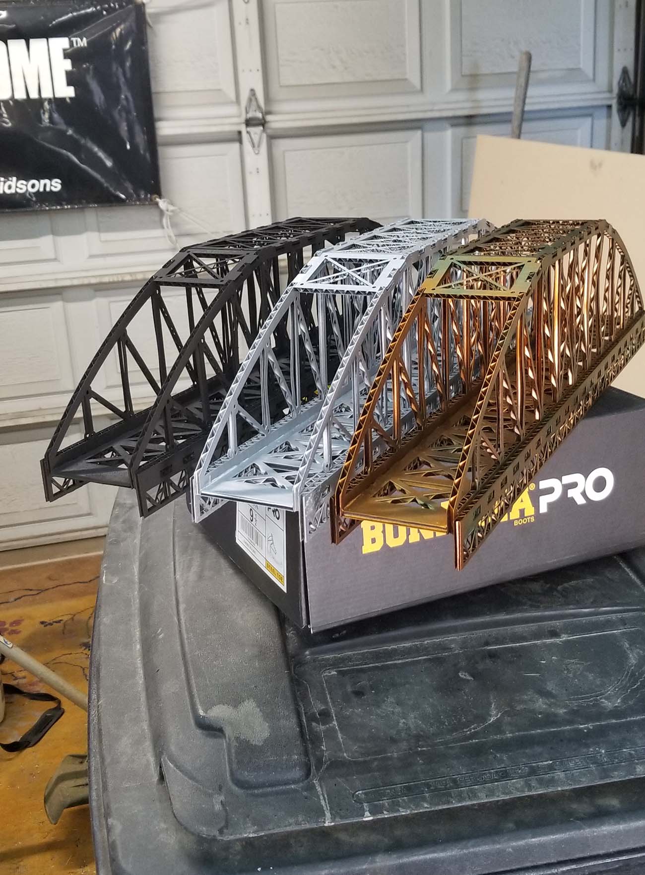
Hope you like the latest pics from my train room – very pleased with my N scale girder bridge.
Happy Modeling
Rich from N.J.”

Wow – an N scale girder bridge! Fiddly work.
And now on to Eric. I found this when I was looking for the Orient Express post the other day (I’d just watched the film).
It really does sum up a lot about this hobby:
He’s been back in touch after his last post:
“Al,
Thanks for getting my story up so quickly. It was great reading all those wonderful comments!
I’ve noticed a lot of people mentioning getting their start in the hobby way back in their childhood. The same with me. I was about 5 years old when my Grandpa who lived in Germany sent my Dad and me some Marklin HO trains.
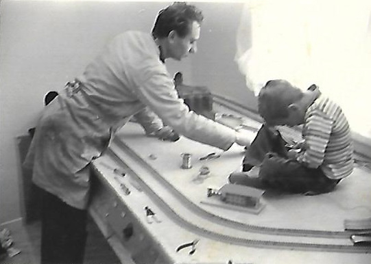
I remember my dad starting a layout that we never finished as we ended up moving to Hawaii. This was back around 1965. I remember a photo of my Dad and me working on the train layout and I just happened to find it again! I have attached it.
Might be interesting to see if others may have photos of way back with their original train sets. It would be real fun to see a collection of old photos and you may want to ask if anyone has any they would like to share.
Please feel free to share my photo on your site if you like. It made me feel real good seeing my Dad again in the picture.
Thanks again for everything you are doing to share this hobby with the world!
Eric”
Now for the latest from Richard:
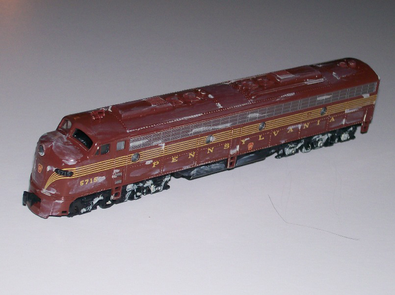
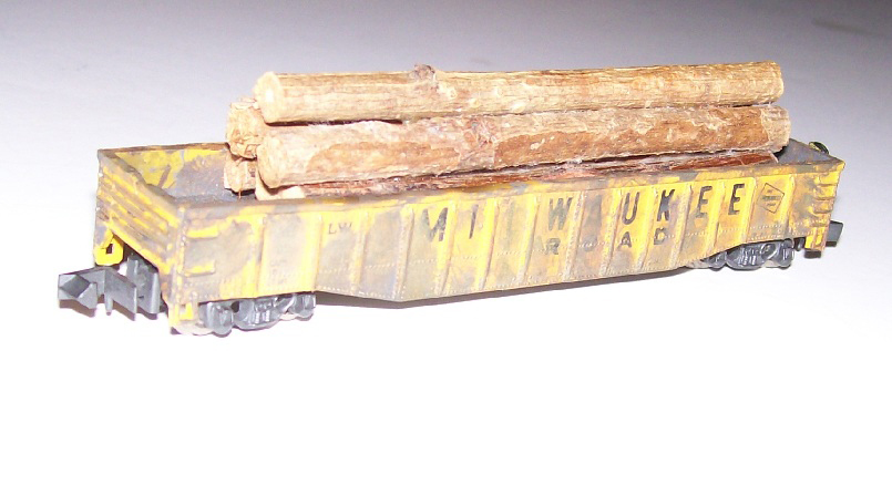
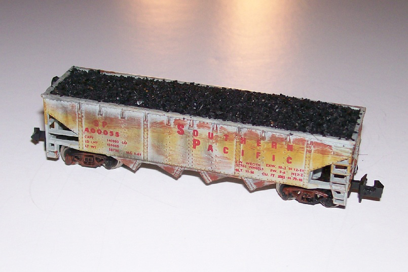
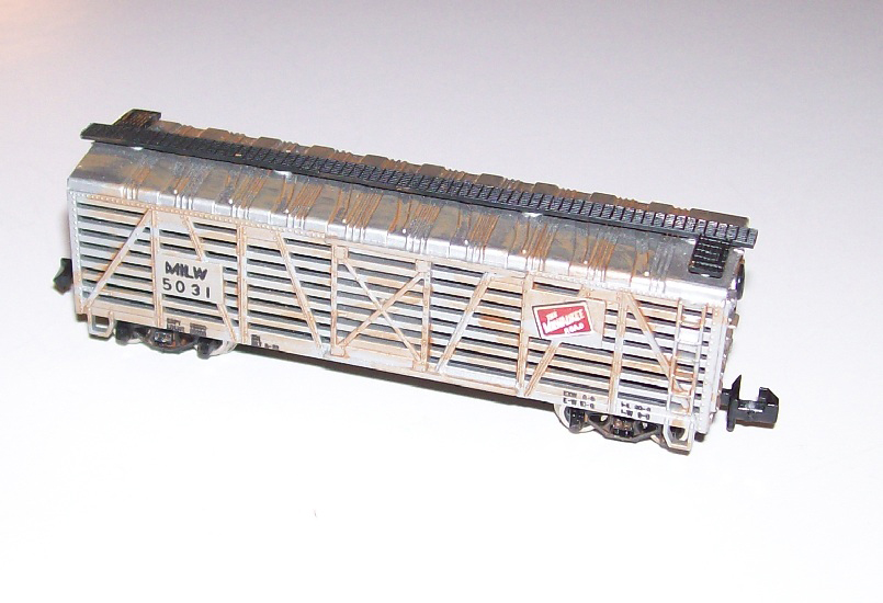
And let’s have a look at Richard’s update. He’s been busy with some fine weathering:
“Hello Al.
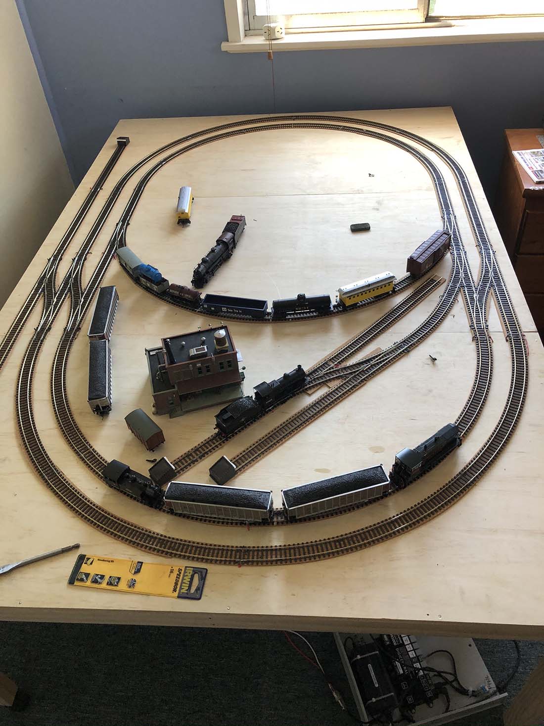
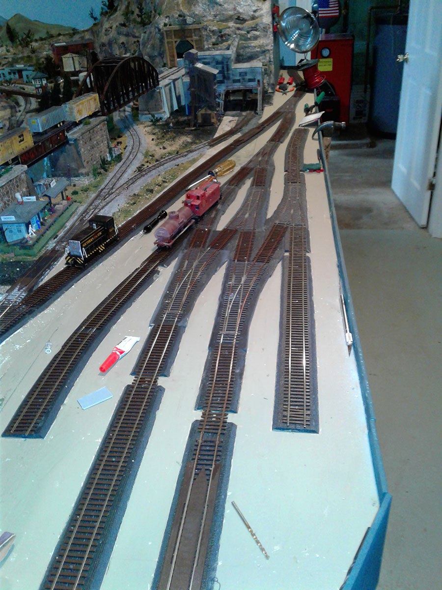
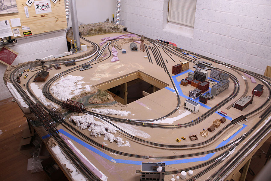
I have been tending to some of the minor improvement tasks on my N-scale “Mountain View Railroad” layout since my first post in early August which you so kindly published on your blog.
I have finally received several shipments of trees which were back ordered for what seemed like an eternity and this has kept me somewhat busy planting them. I now have over 6oo trees on my tiny 4 by 7 foot layout.
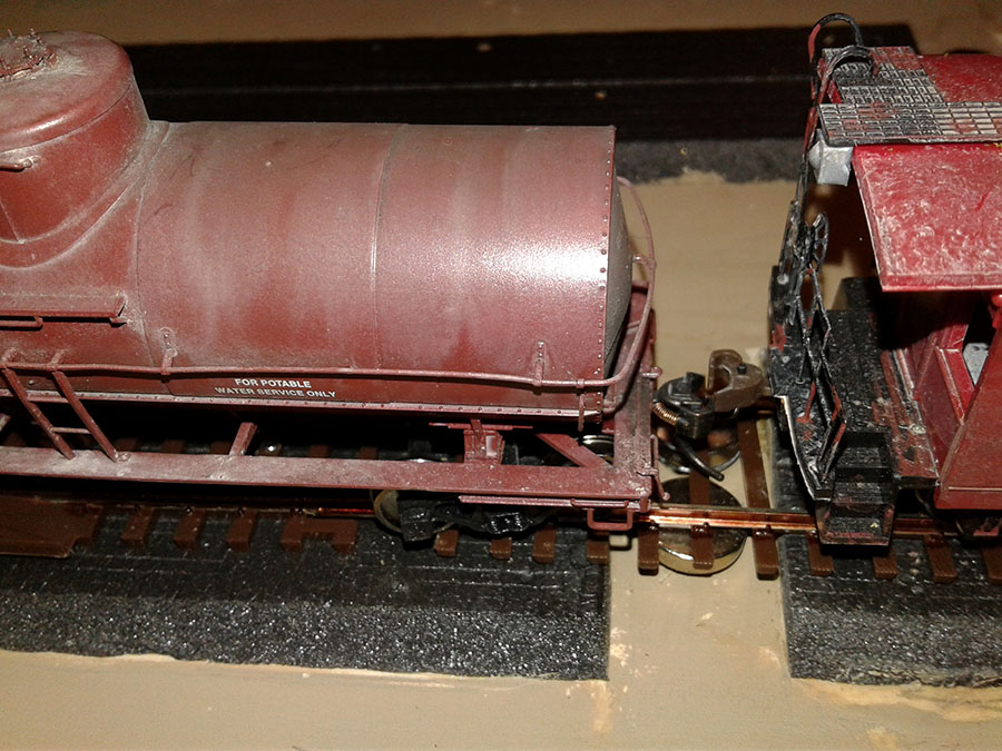
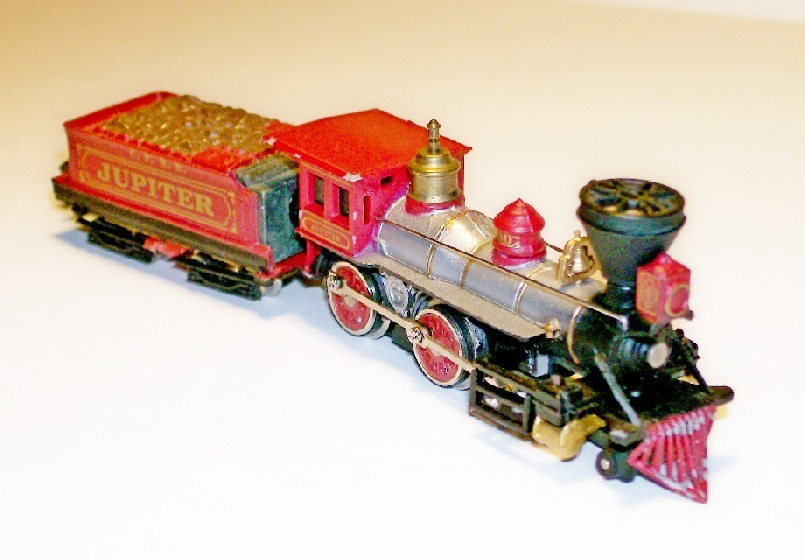
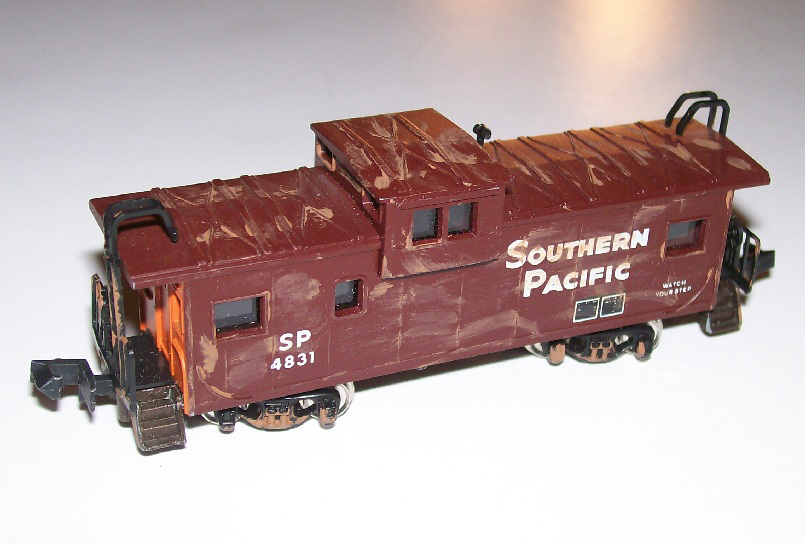
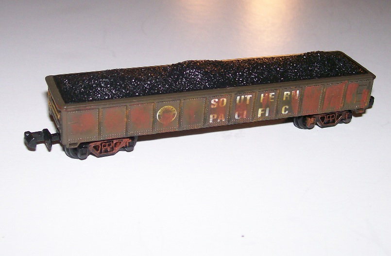
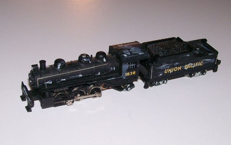
I have also been a bit busy weathering some of my rolling stock. See pics below.
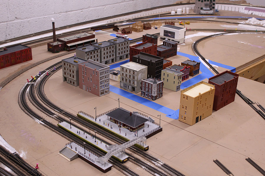
In addition I have been placing additional N-scale persons and vehicles around the layout. I still need lots more people around “Merchant’s Row” and the train station.
My layout is broken down into 4 basic areas:
The “FARM” area
The “RESIDENTIAL” area
The “INDUSTYRIAL” area
The “MERCHANTS ROW and TRAIN STATION” area
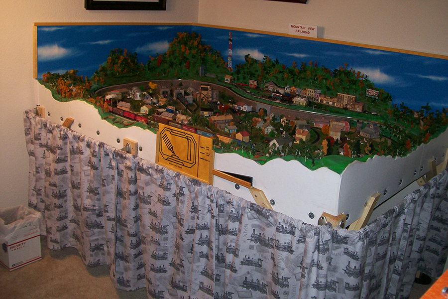
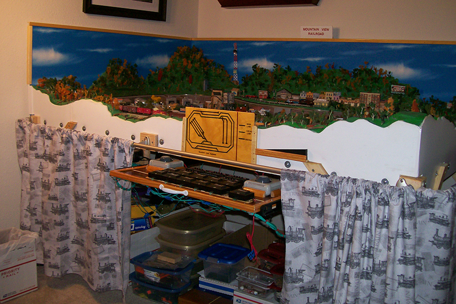
With my limited space of a small bedroom in my apartment, my work space as well as my storage space for my railroad “stuff” and tools was getting to be a bit of a mess. This necessitated purchasing some fabric with a steam locomotive motif print to hide the mess when I am not operating my trains.
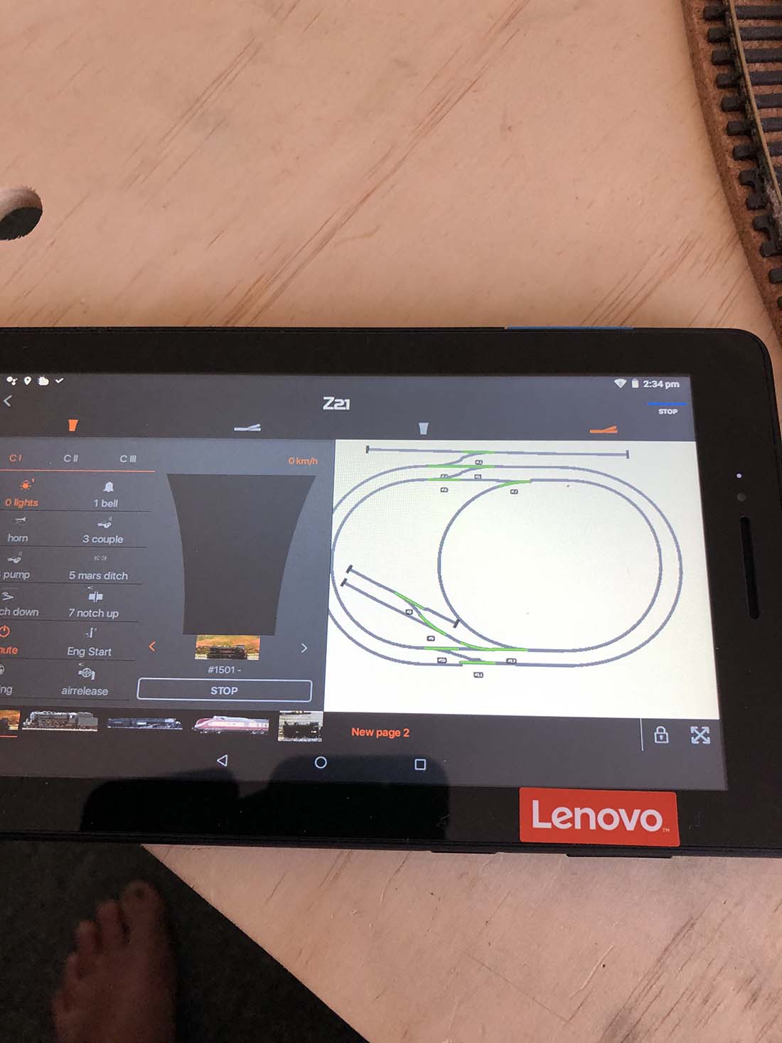
My sisterI fabricated a “skirt” for the two sides of the layout that are not up against walls. There are two fabric panels which provide access to the stored “train stuff” and the engineer’s control panel which is mounted on a set of ball bearing slides designed for a computer keyboard allowing me to slide it beneath the layout platform when not in use.
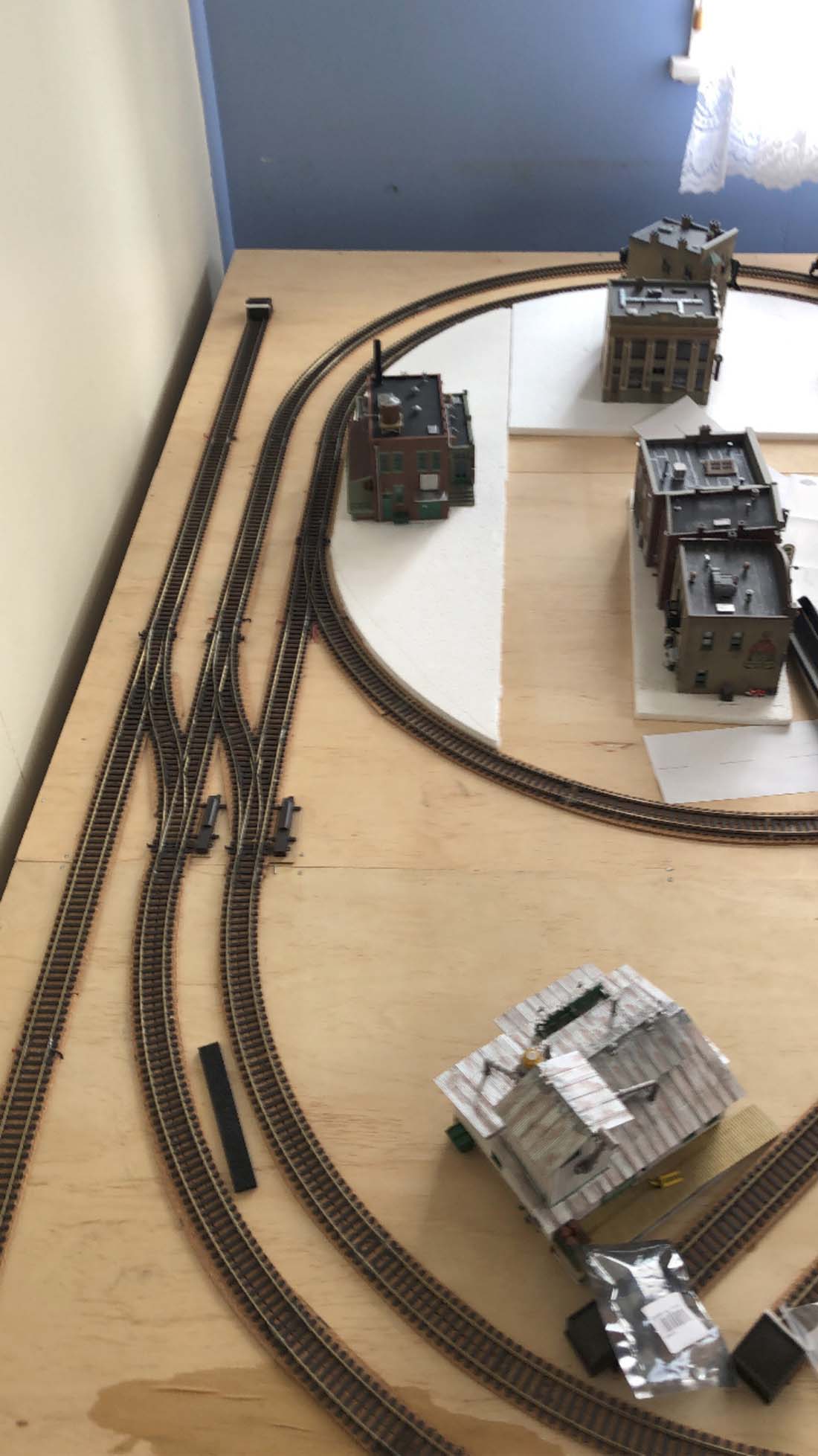
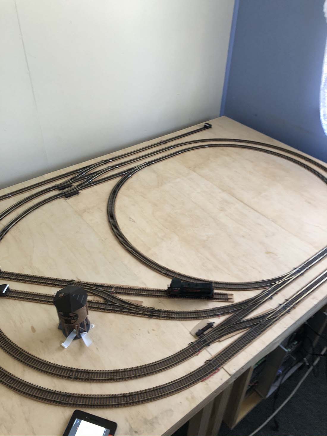
Here’s a couple of pics showing the skirt and the layout in its current state.
Some stats of the layout are as follows:
Approximately 64 feet of Bachmann E-Z track with integrated ballast
6 each right hand #6 Bachmann remote E-Z track turn-outs
5 each left hand #6 Bachmann remote E-Z track turn-outs
7 each Bachmann E-Z track siding bumpers
67 Buildings and other structures
32 Steam and Diesel locomotives
170 Freight and passenger cars
106 automobiles and trucks
30 Street lights
Here’s a few of the weathered rolling stock (there are over 150 more to be weathered) *LOL*
Now that winter is on our doorstep I hope to get a bit more accomplished on my layout………Still lots to do, but it is getting down to the tedious chores that sometimes really tax my patience requiring me to take occasional breaks to maintain my sanity. *LOL*
Thanks for all your hints and tips. Without them I’d be lost. You certainly have done more than your share to support this great hobby. Keep riding the rails.
By the way, do you know of any firms that sell an N-scale powered hand car?
Regards,
Richard
Maryland
USA”
That’s all for today.
A big thanks to Rich, the other Rich and Eric.
Please do keep ’em coming, and if you’d like to make a start on your own masterpiece, the Beginner’s Guide is here.
Best
Al