Dave has been in touch with a question that comes up alot – how to wire reverse loops?
And Bill from Virginia’s been back in touch – with another scenenery ‘how to’.
But let’s start with Dave.
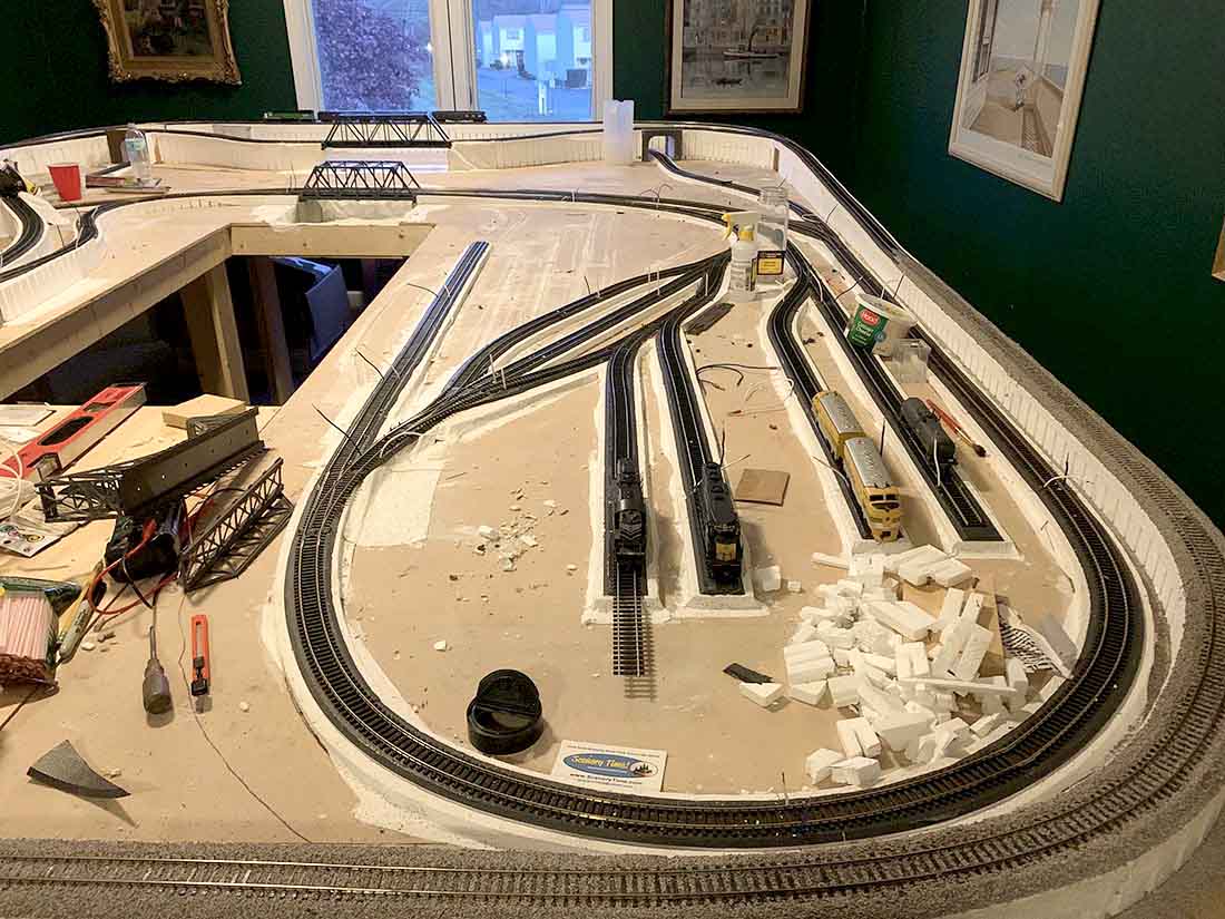
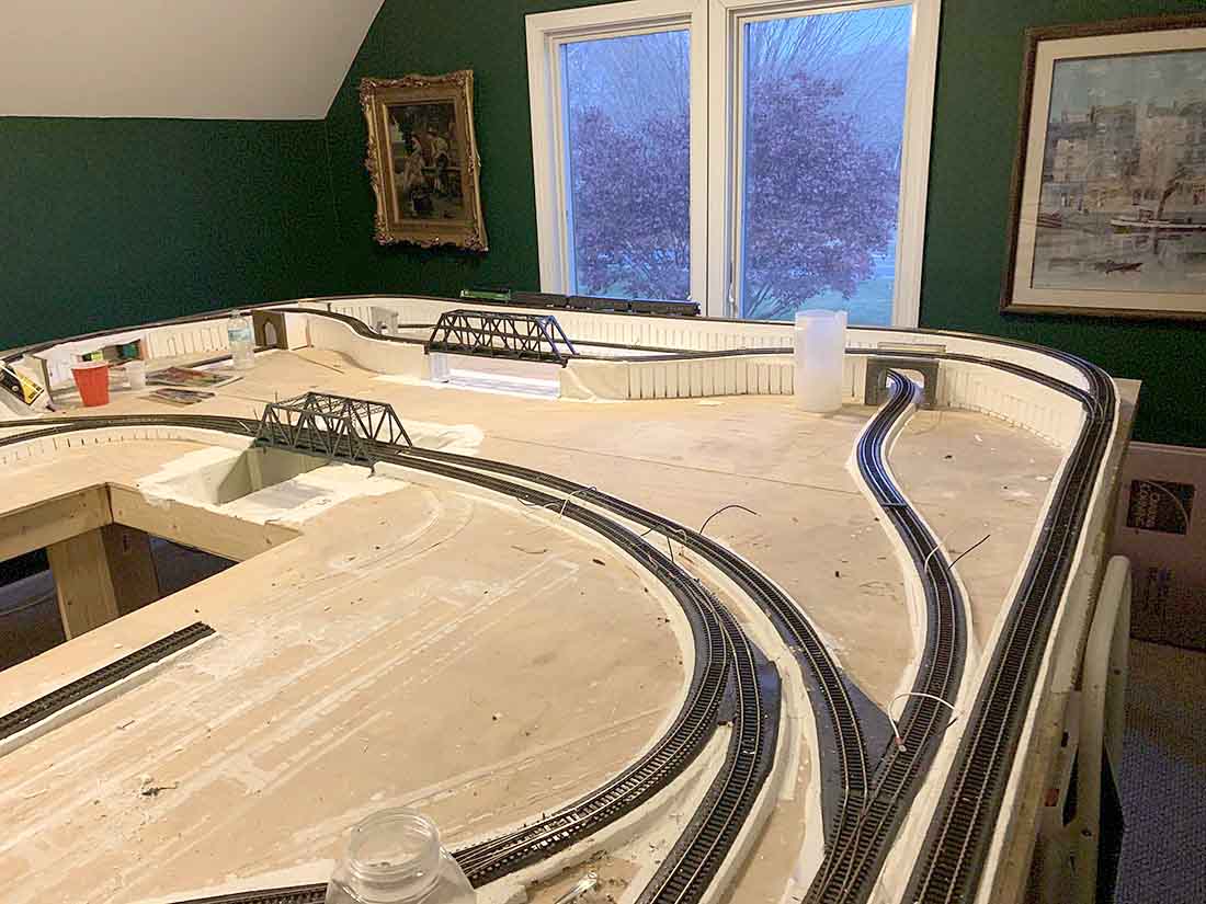
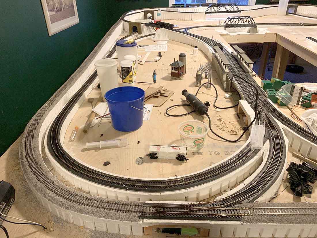
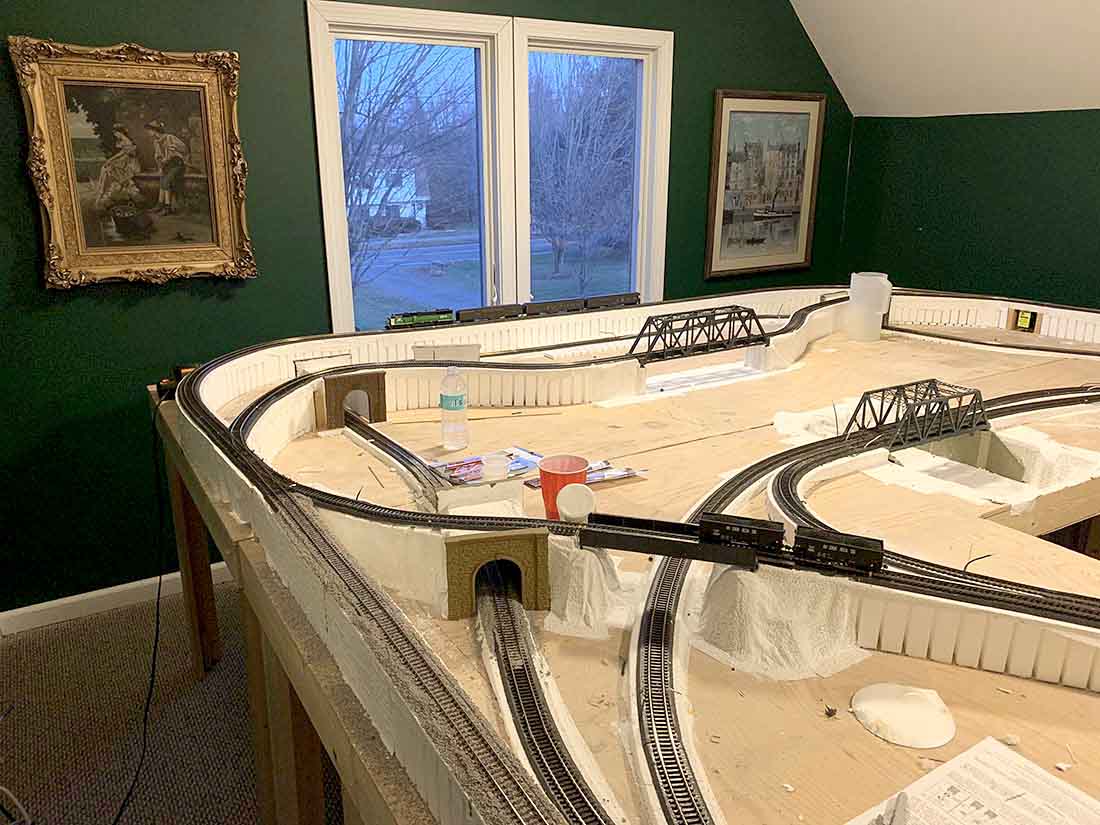
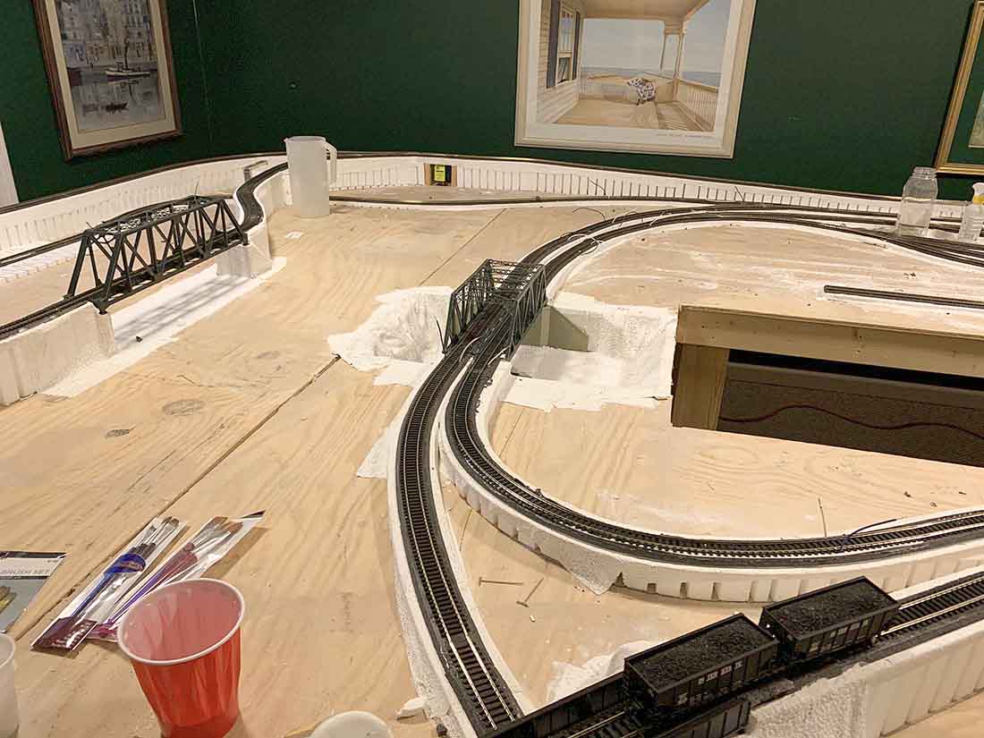
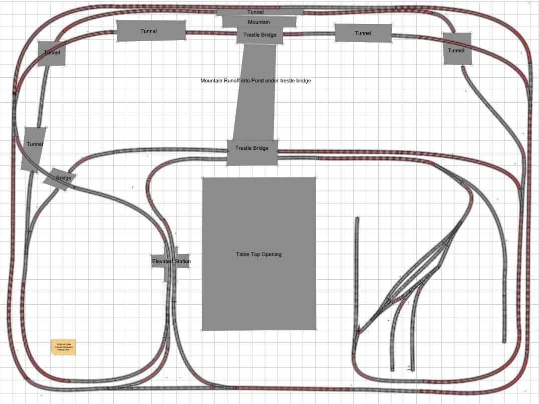
“Here are 5 pics of the layout and a diagram.
Sorry for the mess but I’m trying to ballast the outside loop.
The problem is the reverse loops and how I should wire them. I have NCE as my DCC control although I have it running on the outside loop via DC right now.
I understand I need to insulate blocks or districts, but do I continue to wire the track the same within the district ( Blue wire on the north rail, white wire on the south rail) and use a module for seamless transition?
I do not want to use a DPDT switch if at all possible.
Thanks
Dave”
And Des has sent in this scenery tip:
“Alastair:
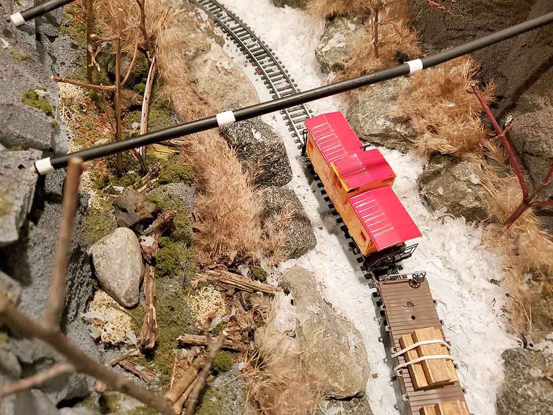
The dried foilage is the winter blooms off cattail plants found in wetland areas.
Des”
Now on to Bill – If you missed his last ‘how to’, it’s here.
Now have a look at how he gets the details into these trees:
“Greetings Al
I had a lot of fun putting the how to’s together for the pine tree build. I created a video for the furnace filter pine trees I showed a picture of in the ‘How To’.
I’m hoping modelers that give it a try and send in pictures of there results. Quick, easy and fun.
Best
Bill in Virginia”
That’s all for this time peeps.
Please do leave a comment below if you can help Dave with his reverse loop.
Please do keep ’em coming. My inbox is looking a bit sad and lonely at the mo.
Andrew’s been back in touch with a wonderful kit bash ‘how to’ – it’s very much like making your own custom model trains.
Embarrassingly, this was sent in ages ago. I discovered it clearing down my emails this week.
“Mommy says I am a hoarder but prefer the term “Collection Connoisseur”, after all, you never know when that little oddity will come in useful.
Besides it lends itself to my objective of “modelling on a shoe string”.
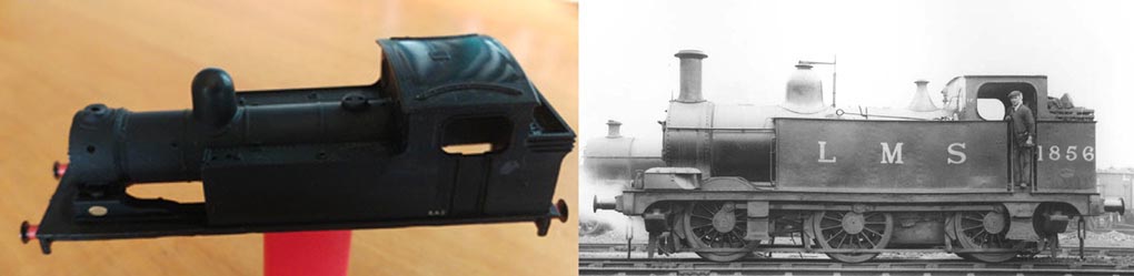
In my opinion, one of the cutest (if one can use such a term when describing railwayania) is the Midland Railway Class 1F (0-6-0T).
I know that there are some fine models out there but where is the fun in that, besides I have been looking for a locomotive to model where I can experiment on a new, low cost method of producing a chassis. So, let’s get on with it.
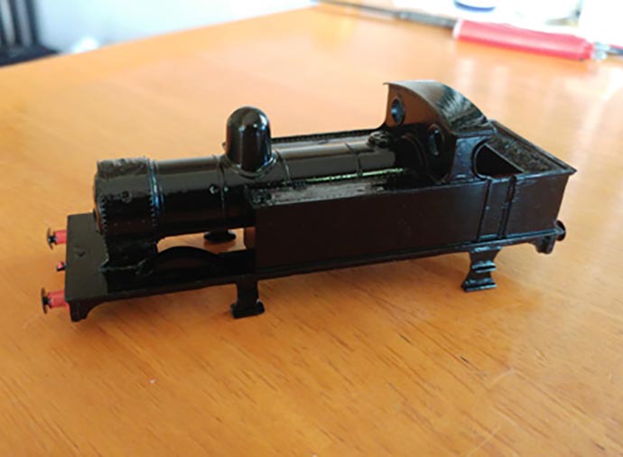
Scratching through my “hoard”, I came across a Mainline J72 body that had lost its chimney and on comparing it to the drawing, I thought that with a small amount of cutting and filing and hacking,
I could transform that into a reasonable facsimile of a Class 1F.
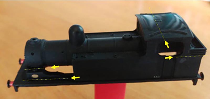
Fortunately for this article, the body was black and Plasticard is white so I think that without too much explanation, the pictures will tell the story.
Using my trusty no 10 scalpel (with that box of Band-aids close at hand), I cut away the front wheel arches and sand boxes and made up new splashers and filler sections.
A portion of the footplate where the sand boxes were was glued in place to cover the resultant gaps. Tamiya putty would as always hide a multitude of sins.
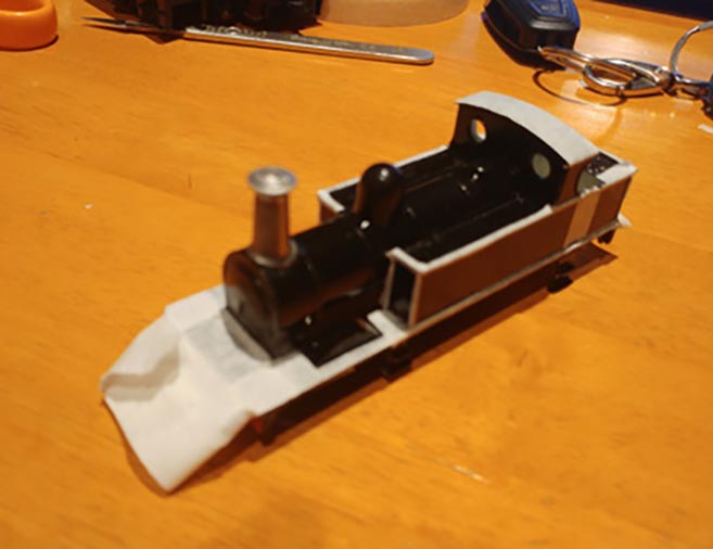
I had set my mind on the early open cab format so I sliced through the roof and reshaped the “windows”.
Obviously, I lost the rear wall between the cab and the coal bunker in the process but was careful to keep as much of the coal as possible, installing a new “wall” to stop the coal from falling out.
Next I cut thin strips of 0.5mm thick Plasticard into lengths and glued them in place to form the ridges around the tanks. Strips of 1mm thick Plasticard was fitted around the coal bunker in similar fashion. The tricky part was the lining around the “windows”where in the same manner 0.3mm Plasticard strips were applied. Once dry, these were sanded with 800grit water paper to ensure that they were smooth and straight.
You probably noticed in the first picture that the body had no steps and these were done last as they tend to break off with too much handling. Once again, 0.5mm Plasticard was used for the legs and 3x3mm Plastruct angle was trimmed to size and glued in place for the steps.
The broken off chimney remains were filed away in order to obtain a smooth rounding. You may find here that the file will slip and the rivets around the smoke box are destroyed in the process. Never mind this is easy to fix with a handy little homemade tool and I digress briefly so that you can make one of your own.
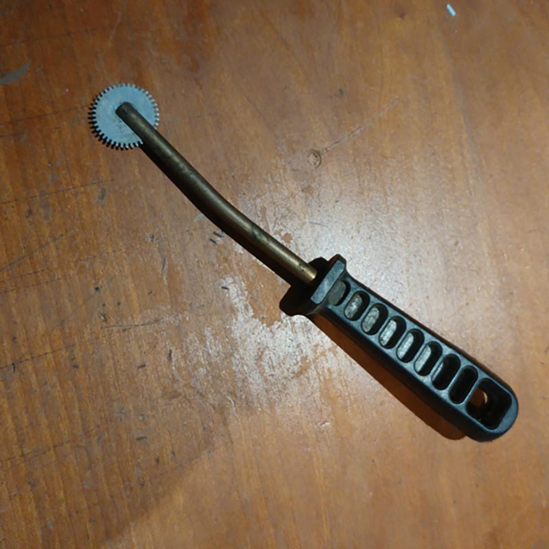
The Rivet Tool: Talk to your local watch-maker/jeweller and request a clock’s brass gear, as fine as possible and approximately 30mm in diameter (I’m sure you must have one lying around from one of your wind-up toys).
Now take a piece of 6mm round brass and drill a 2 or 3mm hole through the centre about 6mm back from the end. Cut a groove wide enough to insert the gear and approximately 30 in from the end. Give a slight bend to the bar (about 15°) approximately 100mm from the cut end.
Insert the gear into the slot and fix in place using a small bolt and nyloc nut. Push the other end into an old file handle and you are done. I would suggest that you round the gear teeth slightly so that there are not too many sharp edges.
So, how now? Well, cut a strip of 0.25mm Plasticard to the same width as the length of your smoke box. Place the Plasticard onto a firm (not hard) surface (a piece of softish timber will do the trick), place a steel straight edge onto the plasticard, approximately 0.5mm from the edge.
Now run the gear of your rivet tool down the length of the Plasticard applying enough pressure to make an indentation without going right through the Plasticard. Repeat on the other side. Next, turn the Plasticard strip over and laminate this to your now smooth smoke box. Hold in place with a clothes peg or other suitable item. You have now repaired the rivets on your smokebox and any mistakes can be hidden with some paint.
Now, back to the subject at hand.
Fill in all the handrail holes with Tamiya putty and once dry, sand smooth finishing with 1200 grit paper. So that is the bodywork pretty much done. Carefully wash with warm soapy water, rinse well with clean water and leave overnight under a cover (like a clean, empty ice cream container) in order to dry.
Avoid touching the body with bare hands as you may well leave an invisible oily residue which once painted, will make you look like a trainee copper taking fingerprints at a crime scene. I use cheap latex gloves for handling at this stage and find that when spraying, keeping them on makes sure the hands are clean.
I stripped off all the loose bits putting them one side for later use and held the body up against a 1:1 scale drawing which in this case was a photograph which I scaled using Adobe Photoshop®. It all looked good so far.
Overspray the entire body with a gloss black and put one side to dry. Once again, the trusty ice cream container comes in useful. I normally resist the urge to mess with it for 2 to 3 days to be sure that the paint dries well. It is important that the paint bonds properly and you may well opt to use a plastic primer before you apply colour. Extending the process byanother 2 to 3 days is well worth the wait.
Scratching about in my junk box, I found a suitable white metal chimney and although not 100%, it looked good enough. A hole was drilled and it was fixed in place with a dab of super glue after first filing away a small amount of the paint so that it bonded.
It is now time to tape up and apply that wonderful Midland Red that makes all their locomotives such an attractive sight to see. Having handled the painted body quite a bit, it received another wash with warm soapy water, rinsed and dried as previously.
With careful reference to as many photographs and pictures as I could find, I taped up all the areas that should remain black.
This entailed cutting thin strips of masking tape on a CLEAN glass surface and carefully applying as required.
I left the smokebox and chimney uncovered as they would require a satin black finish.
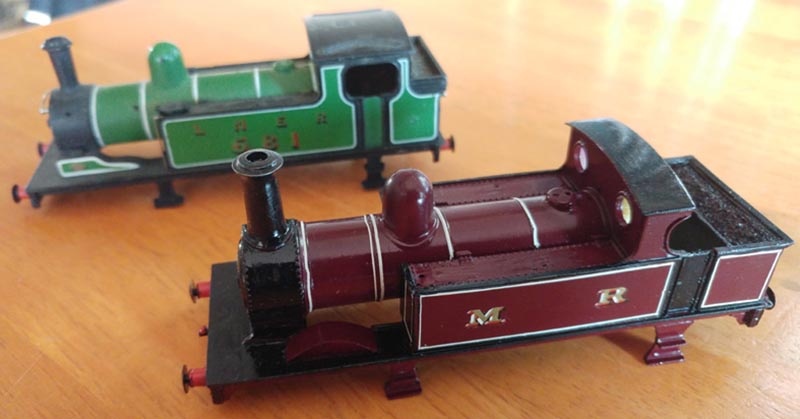
The exact choice of red is up to you but I used what I had and am quite happy with the endresult. Don’t be in too much of a hurry to peel off the masking tape, rather leave it to dry properly.
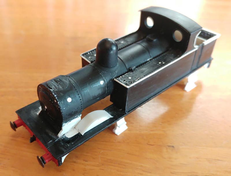
Now apply the decals as per Midland specifications and you are done for all intents and purposes.
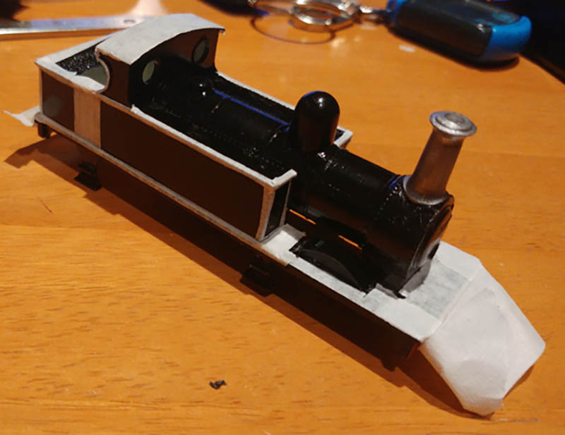
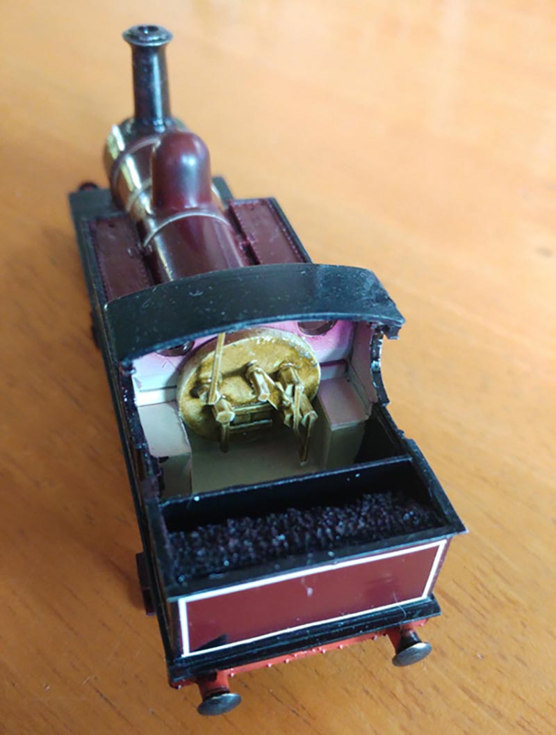
The picture below displays my almost final product.
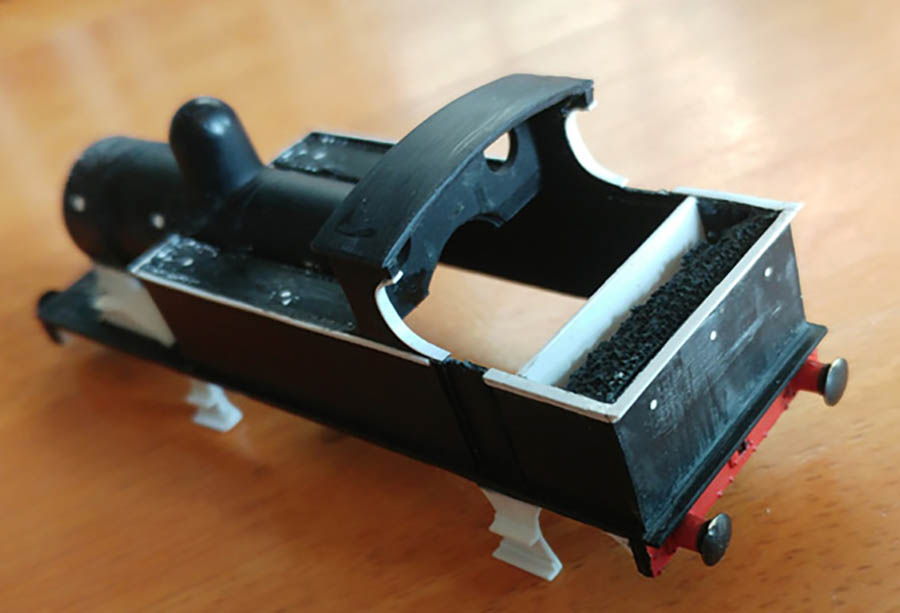
Taking it a step further, I wanted to hide the motor so I decided to fabricate the boiler detail inside the cab.
A bit of extra effort but worth it at the end of the day.
Using bits of scrap, cut and trimmed bits and pieces to produce a not very accurate but reasonable impression. I am not going to go into the detail of this as I think it is fairly obvious from the picture.
You can of course purchase a white metal or plastic option from your local hobby shop but we don’t have that kind of facility here. What I did notice from the few pictures I was able to find on the Internet was that this was predominantly brass with the inside of the cab being white.
Now to find some hand rails and some valves of the right design and I am done!
Currently, I am experimenting with the manufacture of a chassis using etched PCB and 10mm brass and once this is completed and tested, I will follow up with Part 2 on how to make the chassis in this manner.
I hope this provides further inspiration for producing acceptable models on a shoe-string budget.
Andrew”
A huge thank you to Andrew – loved what he’s done. Very clever and very frugal.
I suspect kit bashing is alot cheaper and alot more fun that buying custom model trains.
Now on to Alan.
He’s a man of few words, well none, but he sent in this which I thought was rather good:
That’s all for today folks.
Thanks to Andrew and Alan.
Please do keep ’em coming, I really am running out of stuff!
John’s been in touch with a very helpful piece on model train coach lighting:
“Dear Al,
Thank you for all you do for the most amazing hobby and for all the tips and advice given.
Below is a short tip that some might find helpful.
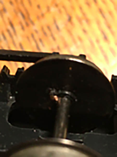
Wheel Contacts for coach lighting
I have loads of carriages and wheel sets where both wheels are insulated from the axel. So as not to have to replace all the wheel sets, I have tried various options for picking up current for coach lighting I have tried contacts on the wheel rim – too much drag; I have tried electric paint between the axle and wheel rim but that does not last; I have looked on the internet but not found anything that is really helpful.
So, my solution may be of use to some out there:
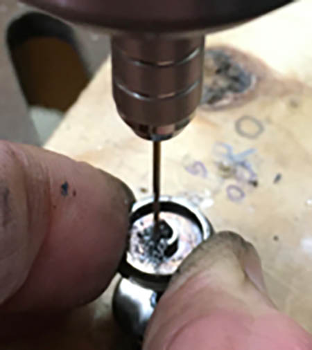
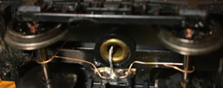
The wheel sets have a small rubber bush fitted to each wheel that insulates it from the axle. Using a drill press, I drill a small hole in one bush on each axle. The drill size needs to be small (0.5-0.75mm) so as to drill against the axel through the rubber bush and through the wheel.
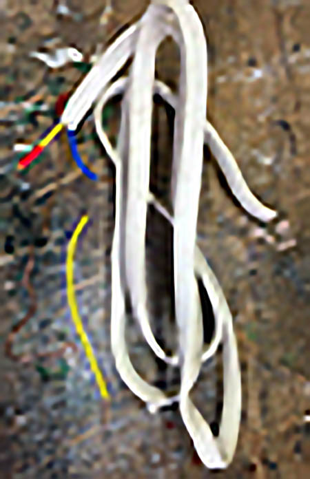
Insert a piece of copper wire extracted from an electrical cable – it needs to be a tight fit (wiggle it round and back and forth, until it goes through).
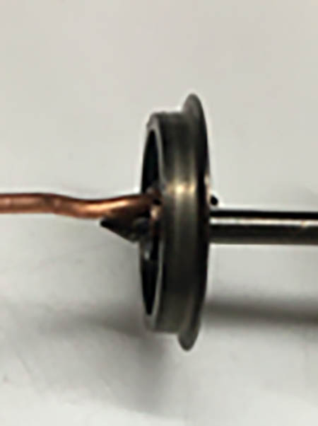
Trim it off leaving about 0.5mm protruding each side. Using a par of pliers on each end of the piece of wire and crimp the wire to ensure a really tight fit.
Check the gauge of the wheels as they sometimes do move on the axle during the work. The small piece of copper wire cannot be seen behind the axle box and you have good contact.
I have successfully installed lighting in fifteen carriages.
Best Wishes
John”
A big thanks to John for sharing his model train coach lighting tips.
Now on to Bob:
“Hi Al,
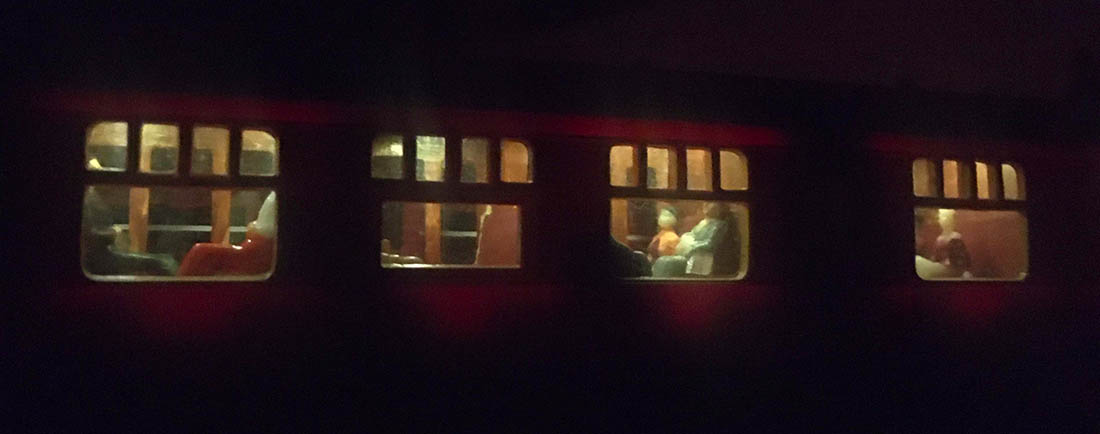
I was moving the tructrain out of my way the other day and it looked so good when I was running it that I decided to take some pics of it.
So here it is running on track 2 over the lift bridge passing through part of the town toward two crossings; and past the ice cream stand I had previously posted.
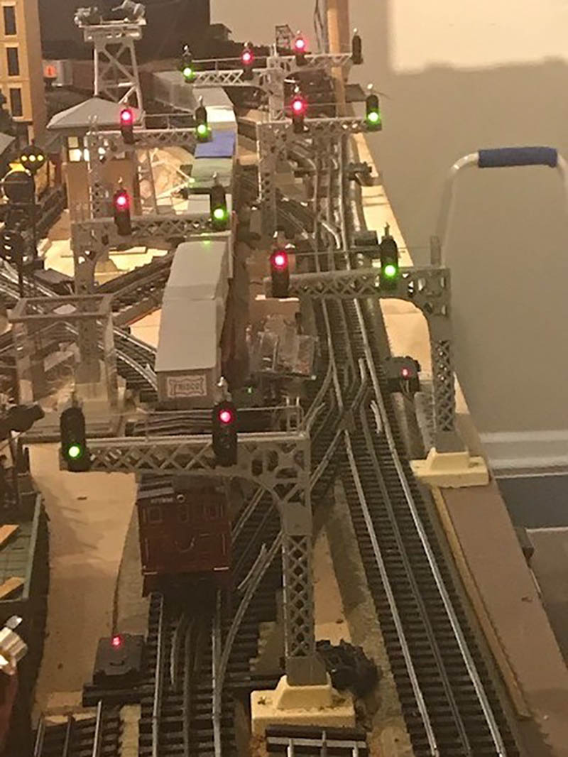
The PRR style signal bridge does not give accurate indications. I configured it to show stop when the bridges raise.
I activated the raised bridge circuit to make the signal look better in the pics.
The left hand signal on the bridge is actually showing a turnout position for track 1 on the other end of the bridge.
The green light signal is showing another turnout on track 2. My son who is an engineer had some angst about that one!
I used a different configuration on the other end of the bridge for the bridge up signal.
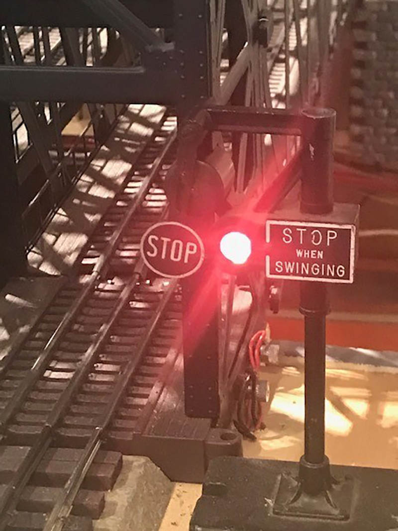
There is a lift bridge in the Newark, NJ area that I passed at times during my commute. I always wanted to get a picture; but a main truck route runs right next to the bridge. Just before the bridge is a smash board that drops when the bridge is raising.
I always wanted to model that, and thought about using an HO crossing gate; but then decided to use a Lionel Banjo signal, as seen in a still shot.
All the single mast signals also are turnout indicators. Many of the turnouts are crossovers so the signals help me stay out of trouble.
I wired the turnouts to throw together so the dual signal changes as well. The red roofed station platform is at least 70 years old. I added a close up still shot. It’s made out of wood with a metal mesh on it. I don’t know if my Dad made it or picked it up somewhere. It looks like it’s closer to Standard gauge, but it’s a keeper.
The Girard station is tin and was made by Marx. It is also up there in years as it was on my original layout as a boy. As you can see the layout isn’t quite finished to say the least; although I got quite a bit done these last few months.