Don’s been in touch with some model train tips – ignore them at your peril.
It’s very good of him to share it. He’s not alone, I often get mails like his:
“Dear Alastair,
Five years ago I started a layout in the basement of our house. It was made of plywood table sections. After completing all the tables we decided to move to a condo.
I was able to use the loft with an attached bath. Now to share all my mistakes.
1. I was able to use the tables after I arranged them as a jigsaw puzzle. This forced me to make a track plan that fit the tables. The curves were too tight. So, I widened the tables. This caused tight isles. Starting over should begin with a clean sheet of paper.
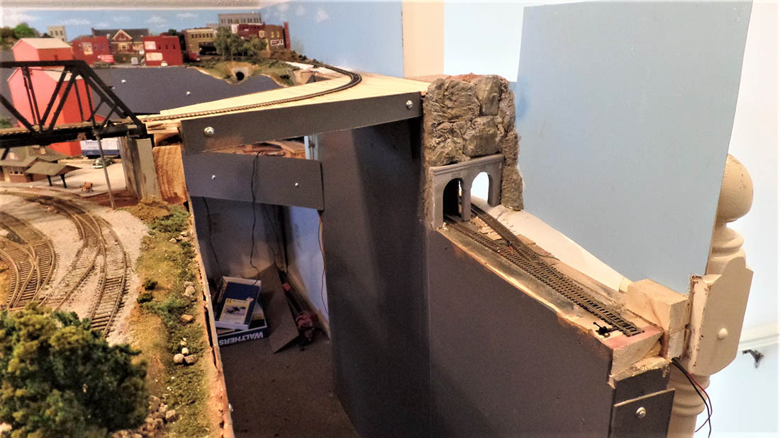
2. I decided on a mountain railroad. This allowed tracks to pass over each other. It smoothed out the plan and lengthened runs. The elevation change was 18 inches. Wiring leeds to the track were over two feet to get under the plywood table. Most switch motors were above the plywood and hidden.
I cut five inch access holes in the plywood for future access after scenery would hide them. Disaster. Putting my hand through the hole limited my view. It was dark and required temporary lighting. While they were wired before scenery, Changing to DCC took advantage of the other terminals. Don’t make a layout with elevation changes more than four inches.
3. Not knowing about DCC I bought many nice switches off Ebay. Some were even brass. While they functioned fine mechanically, many were a nightmare electrically. Because of DCC I had to replace four switches after the scenery was in. Also, DCC required more electrical drops. This required 24 inch drill bits to get from the elevated track and through the plywood.
4. Before DCC I had to limit train length because of some four degree slopes. With DCC I figured I could add helpers. One problem, helpers of different types than the lead engine ran at slightly different speeds causing a tug of war. They can be speed matched with a recorder or an oval loop. I had neither. So, limit slopes to two degrees or less.
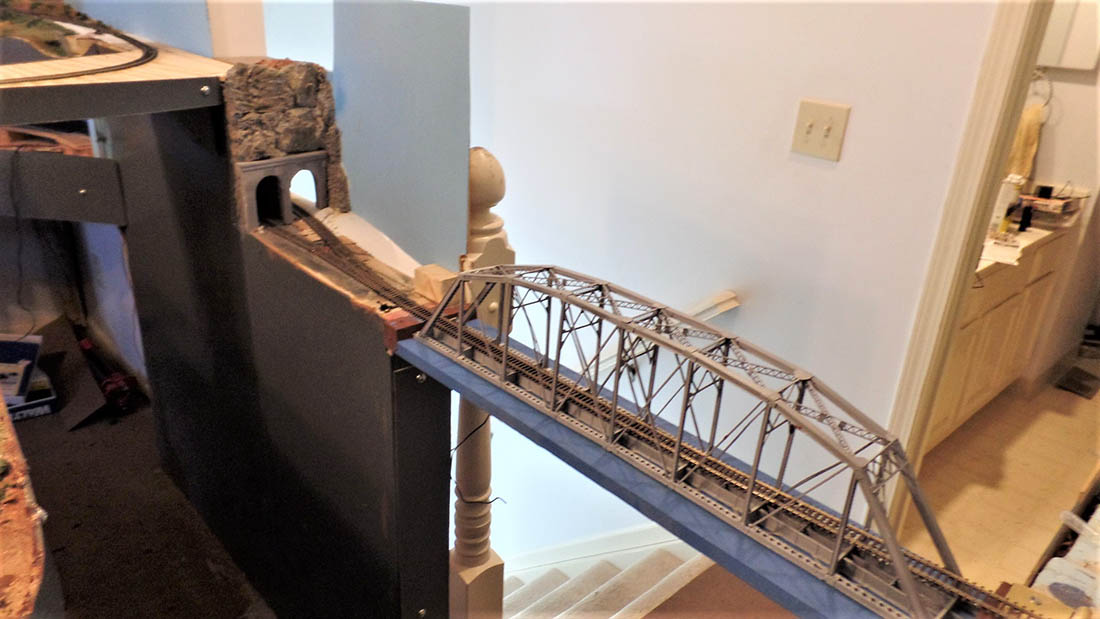
5. The last straw. Because of the elevated track, the two ends of the track didn’t match and made this a point to point railroad. I had a return loop at the low end and needed one at the high end.
I had planned for this. I was going to go through the wall into the bath and loop over the bathtub. The bathroom was not being used. We had others on the main floor. Last fall I mentioned my plan to my wife, proud of my solution. She mentioned, as a soon to be widow, she would turn the train room into a sewing room.
Plan B. I had a lift section to enter the space. I added two more to make a return loop. I am too old to duck under (76) so I was continuously moving them. Misalignments, derailments, and a lot of work. So, I am ripping it out and starting over. I wish I’d know these model train tips before!
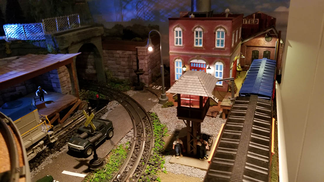
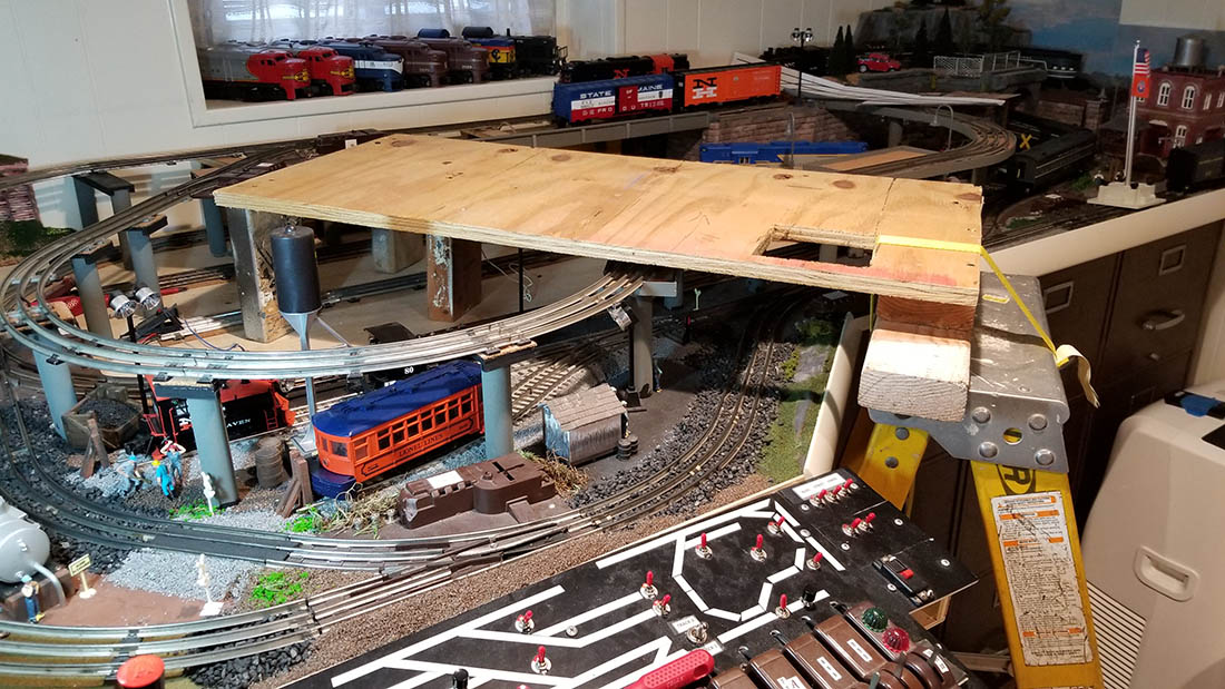
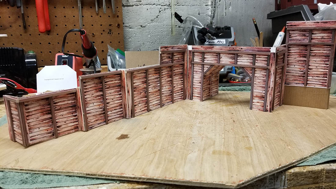
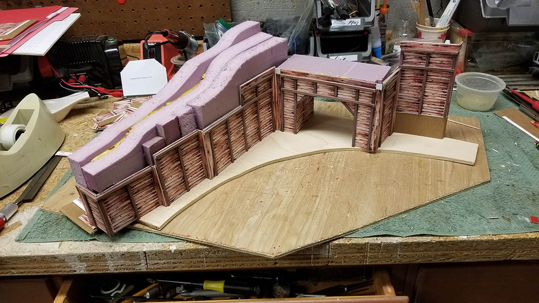
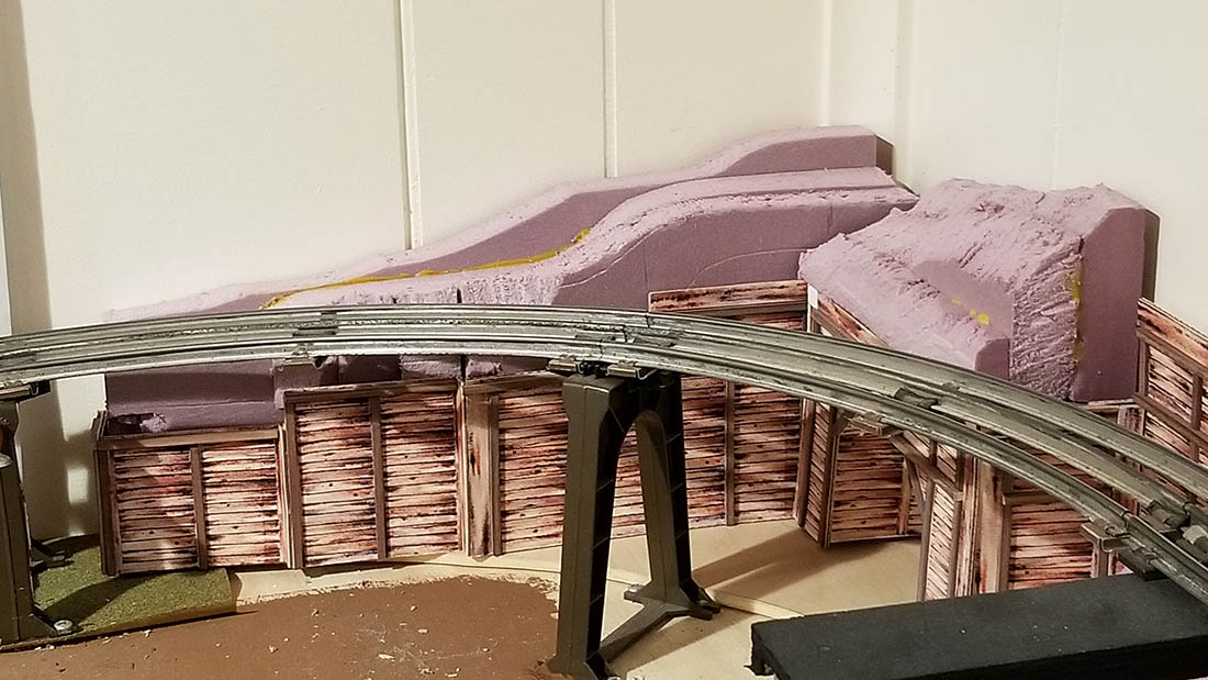
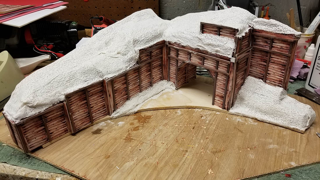
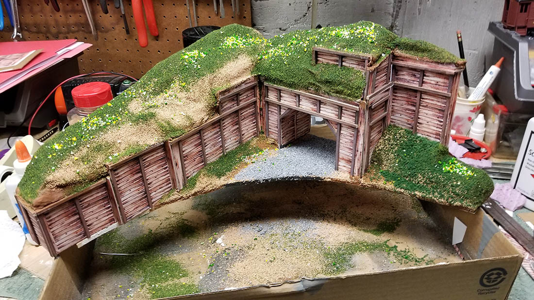
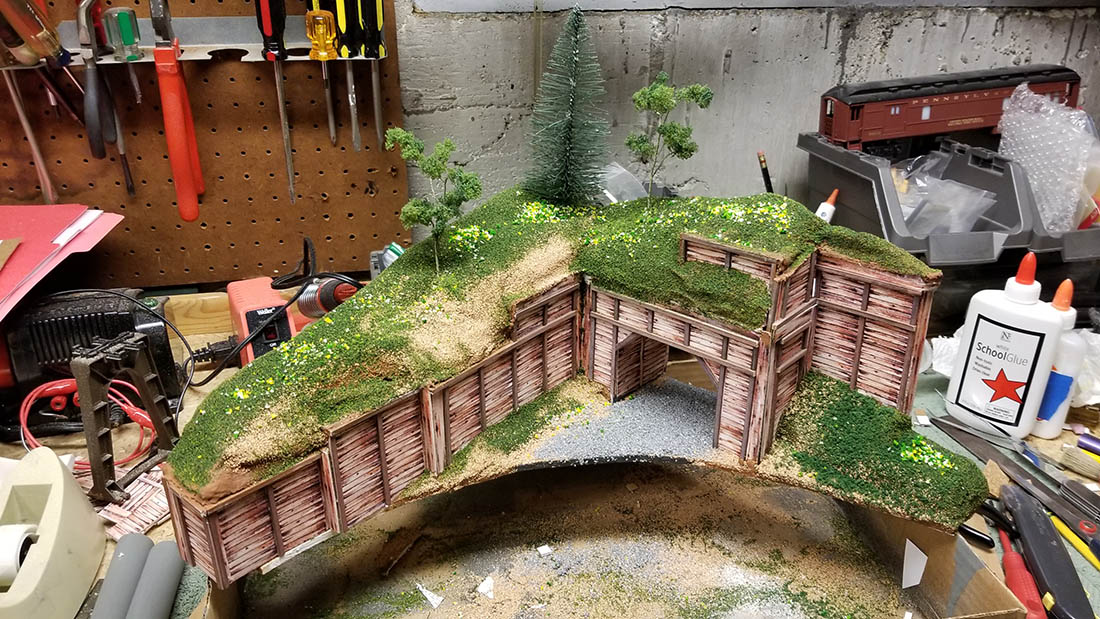
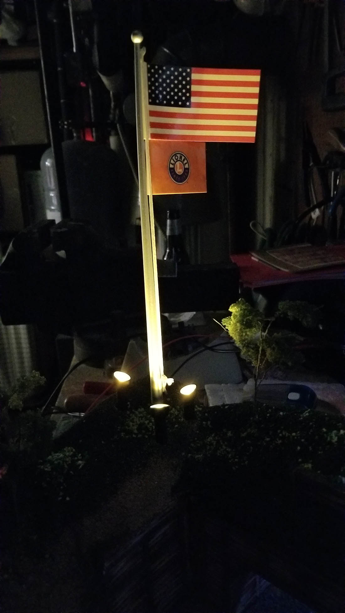
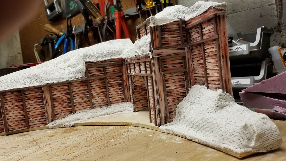
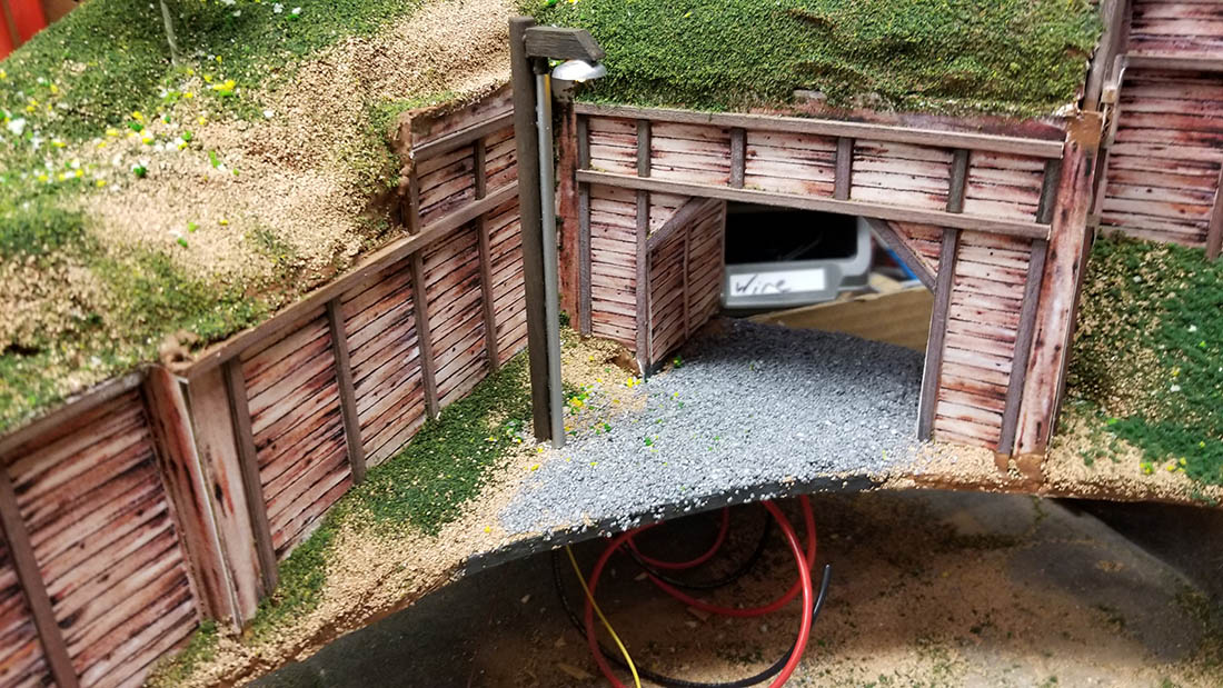
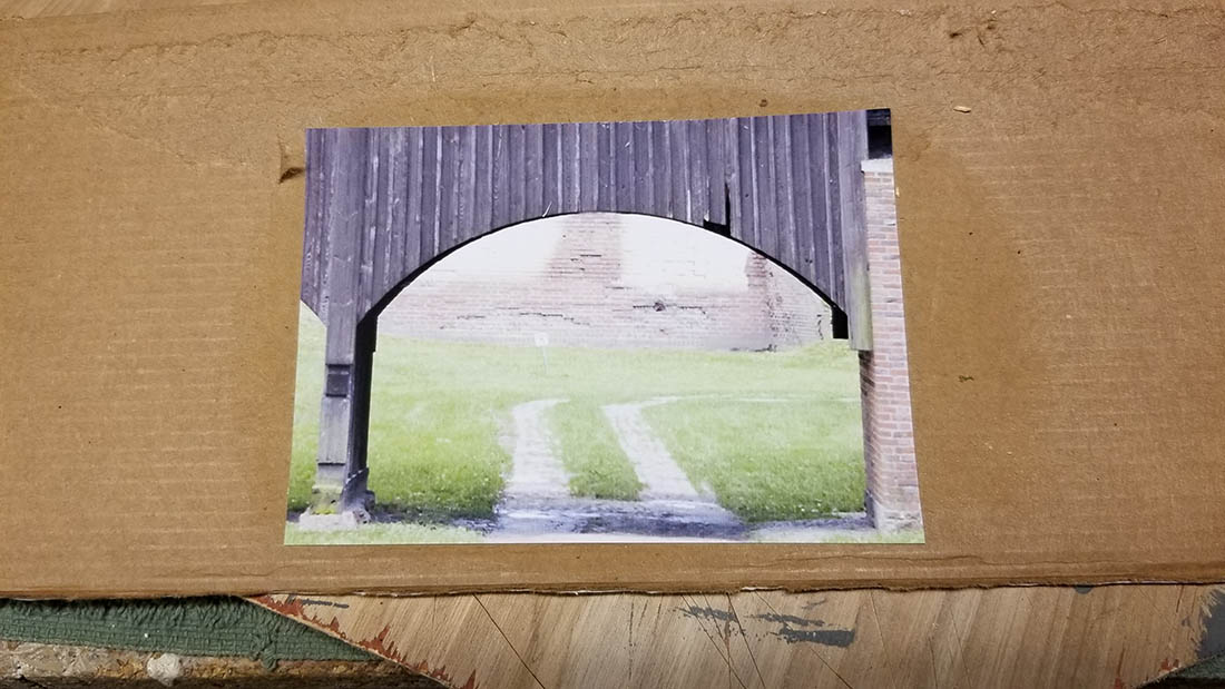
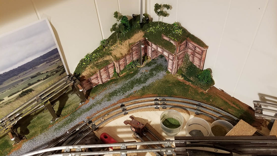
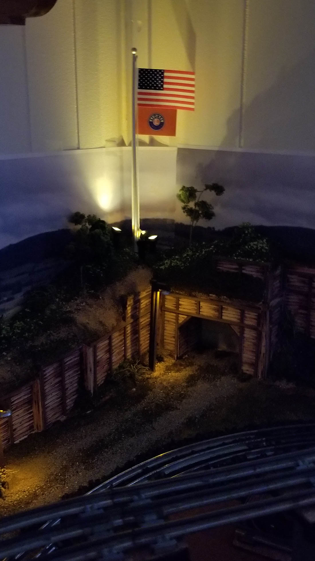
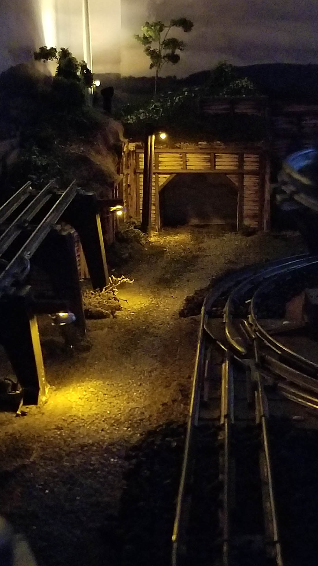
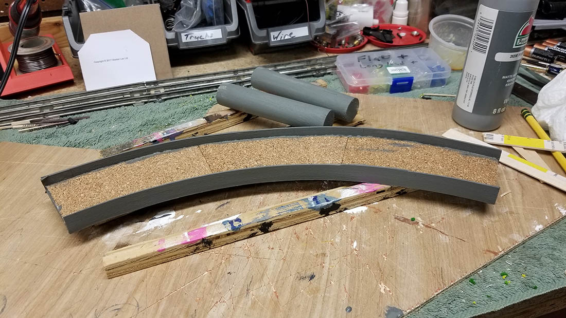
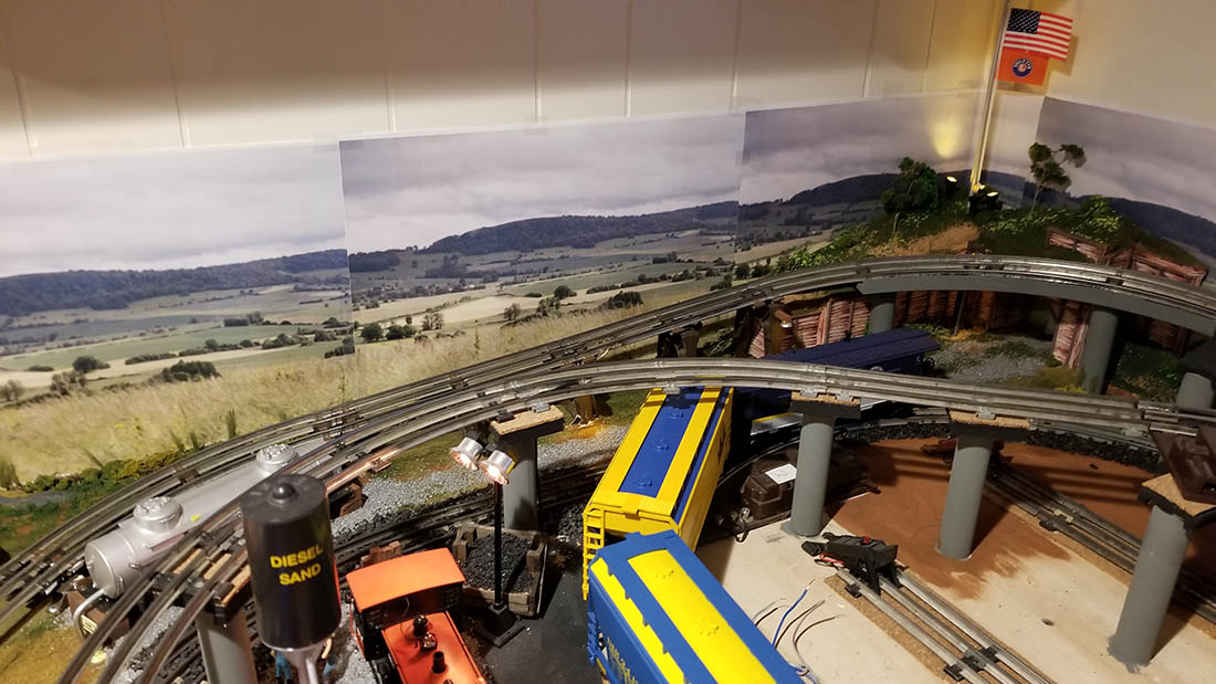
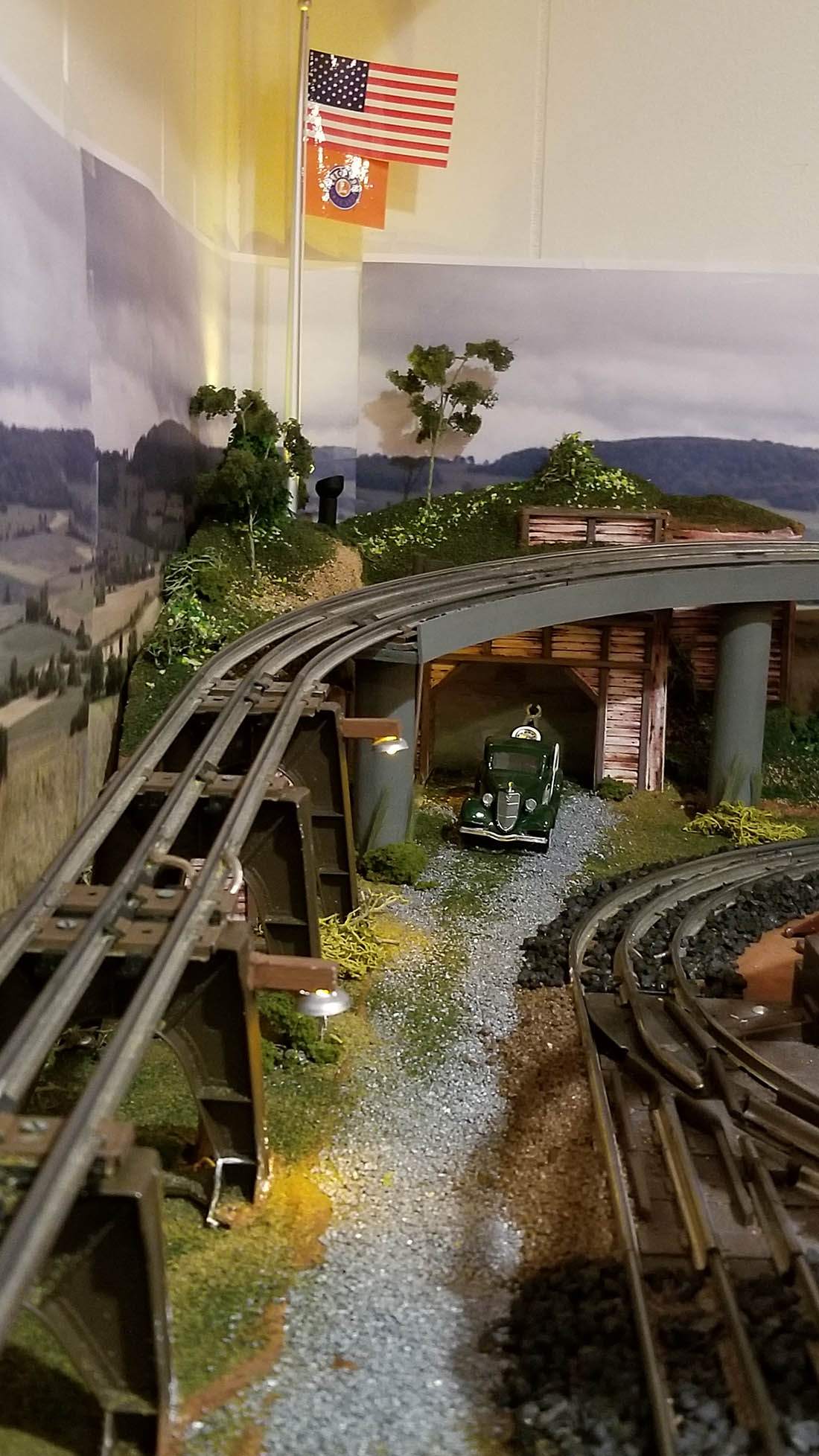
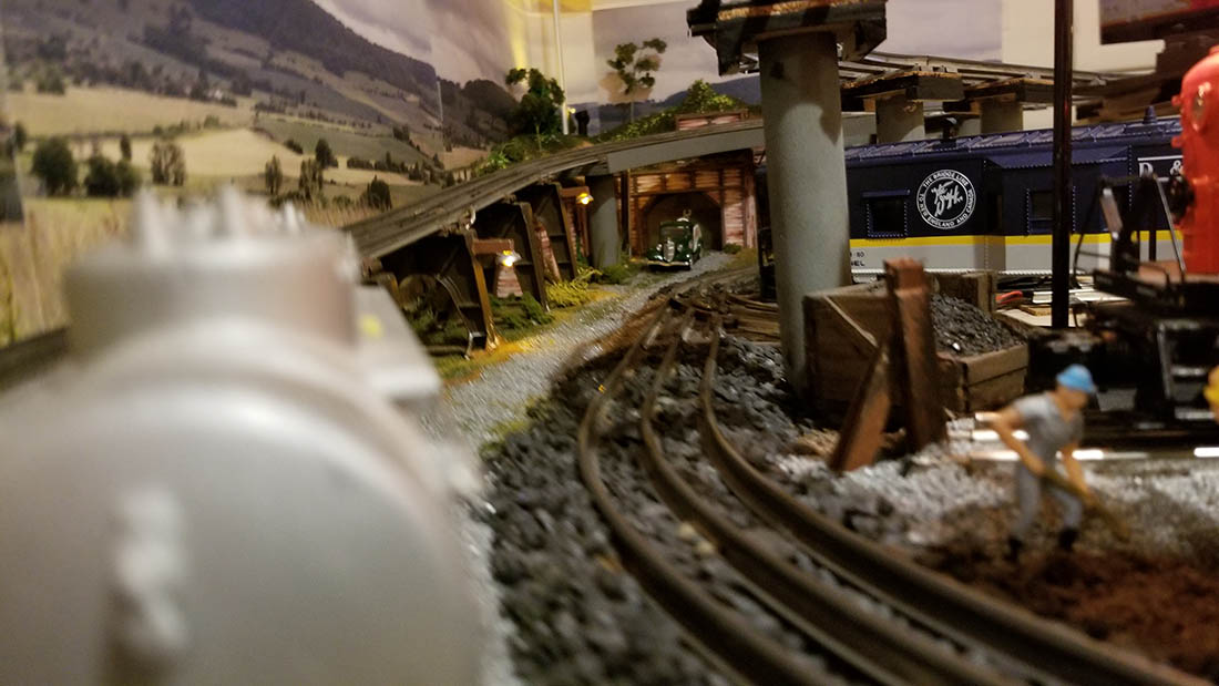
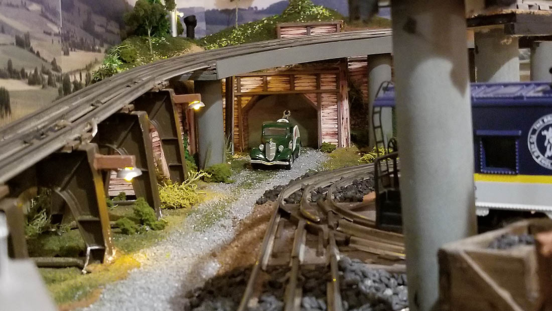
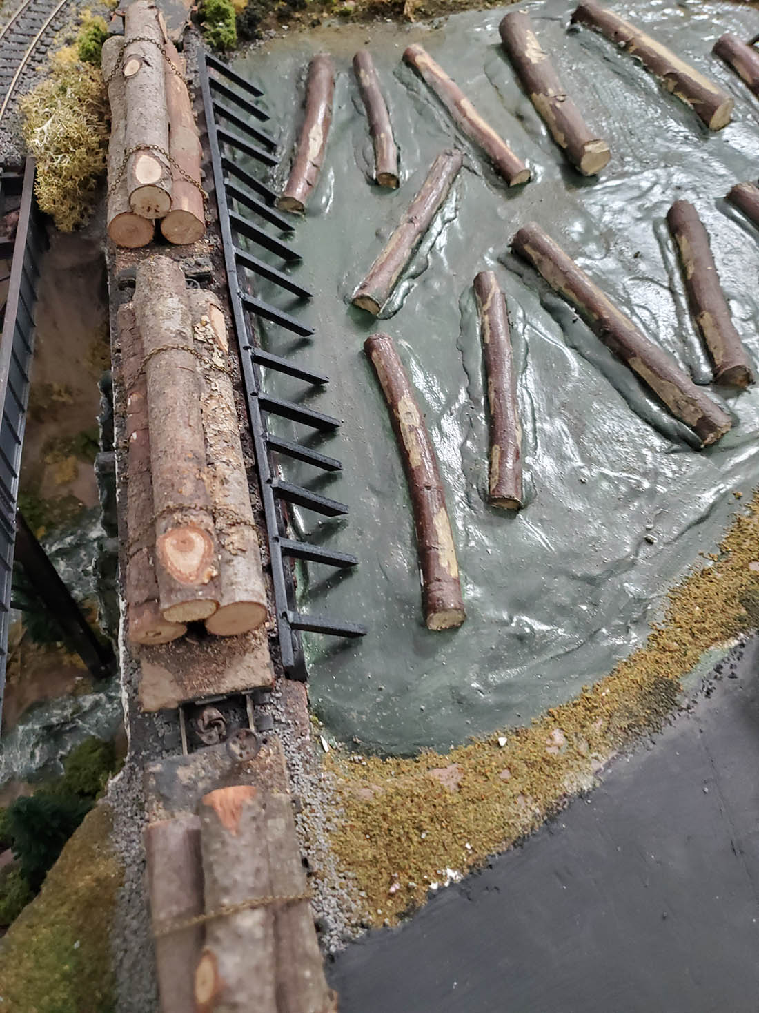
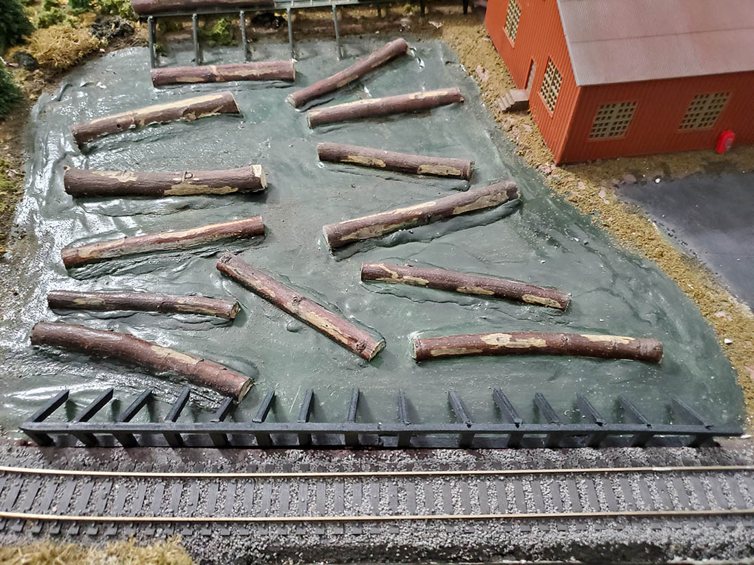
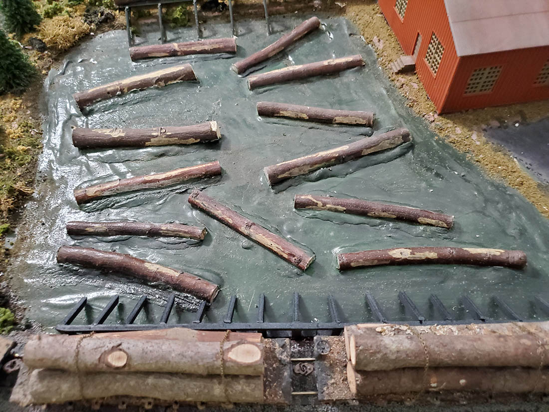
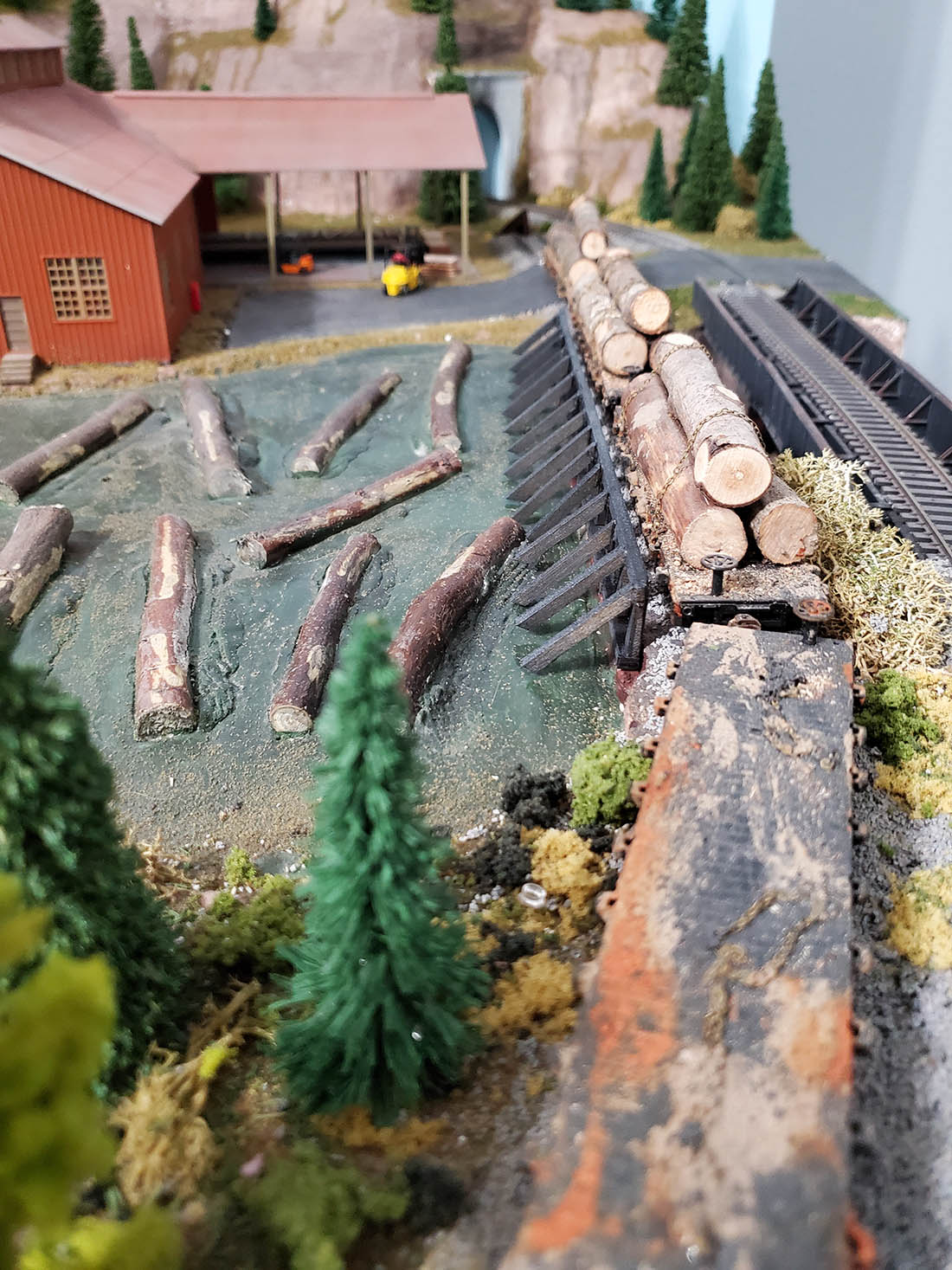
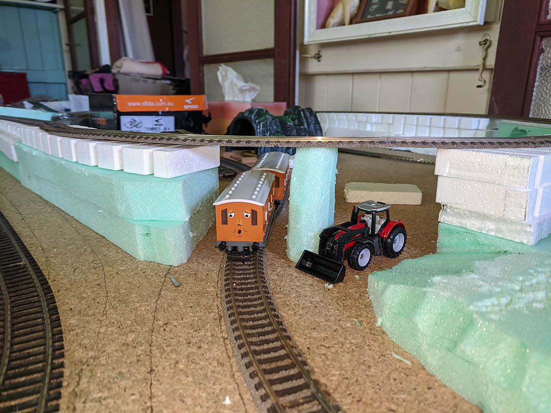
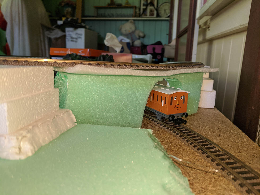
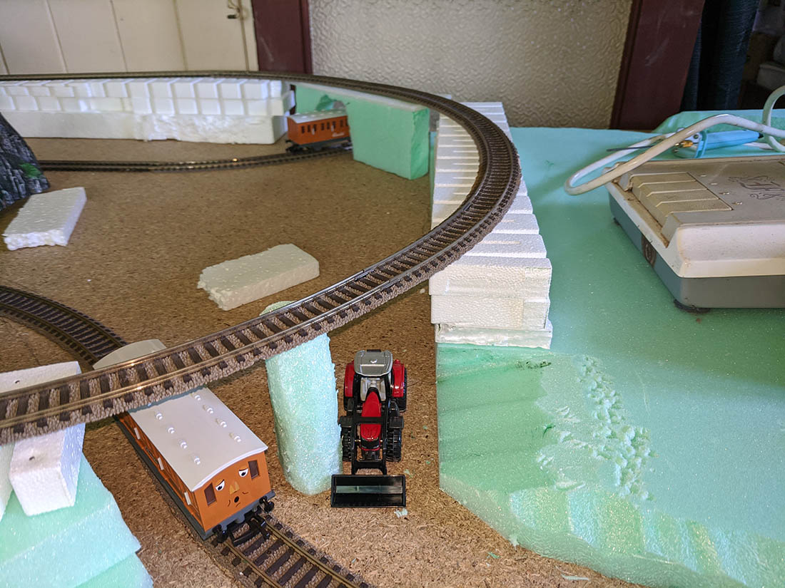
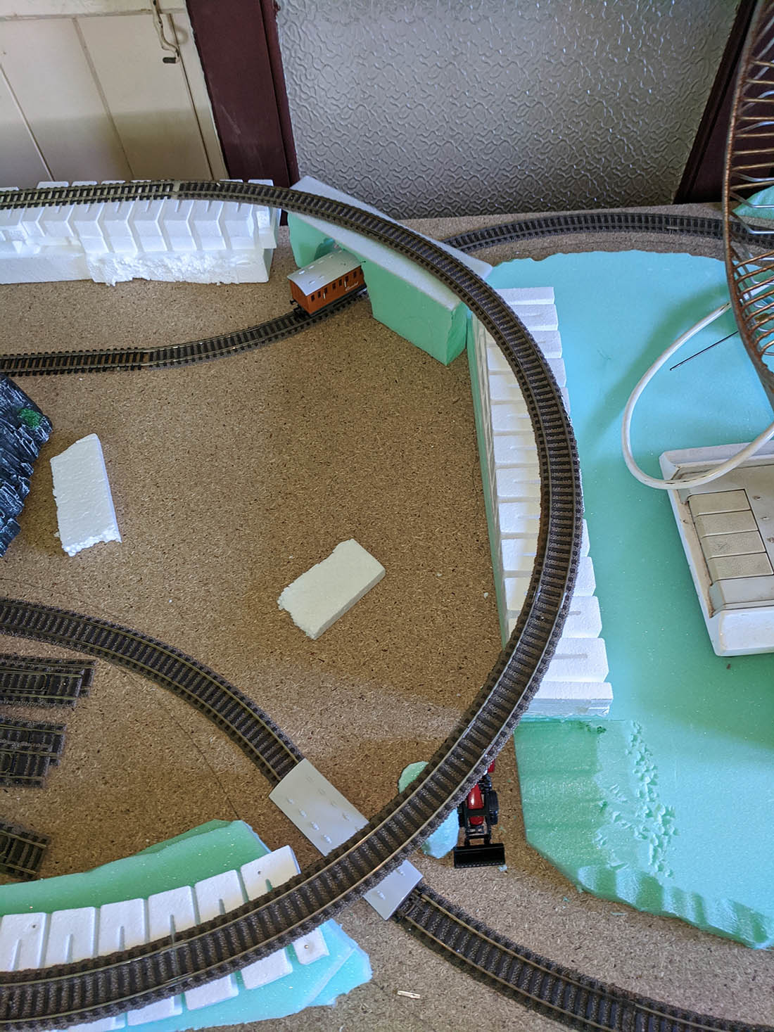
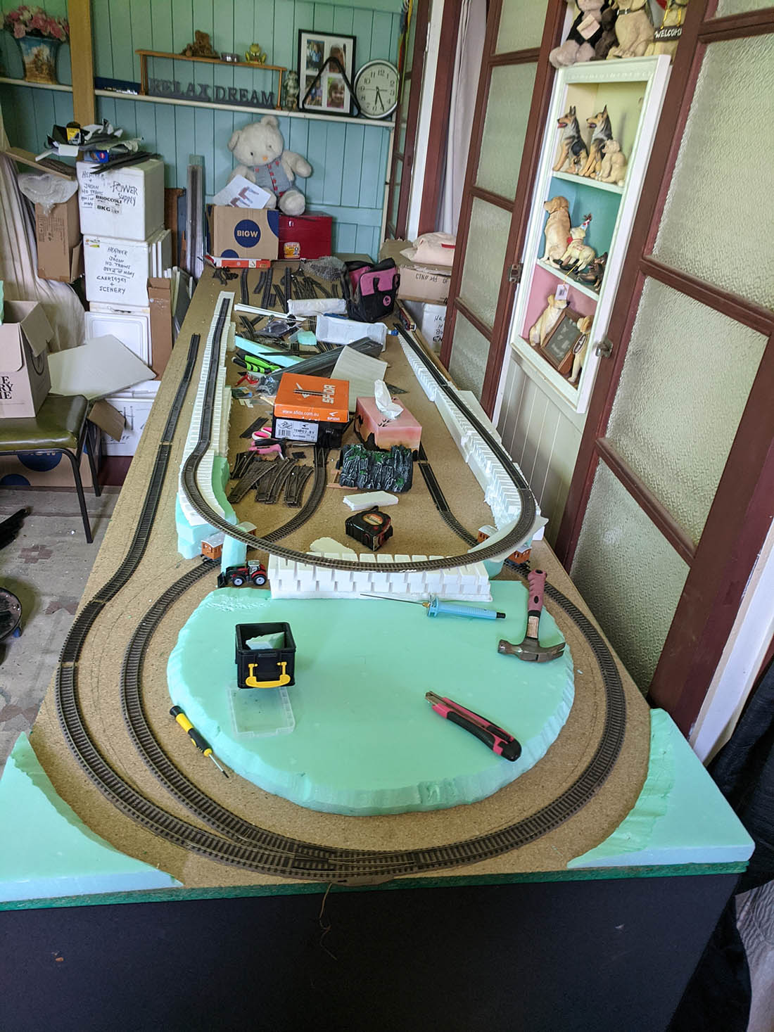
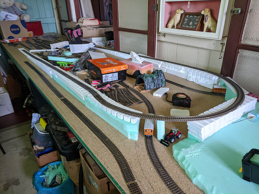
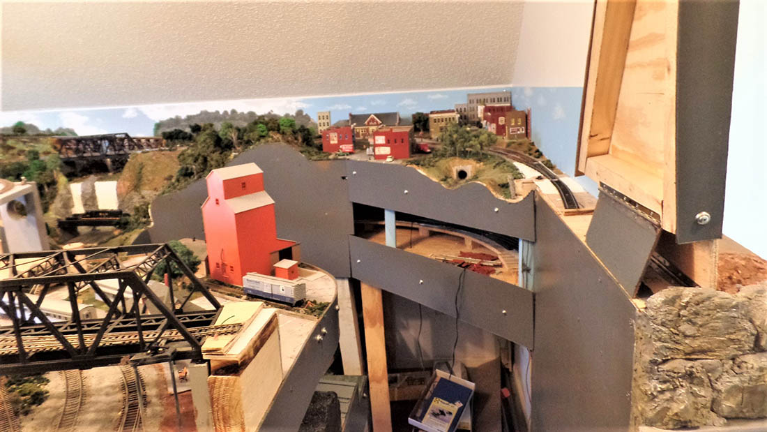
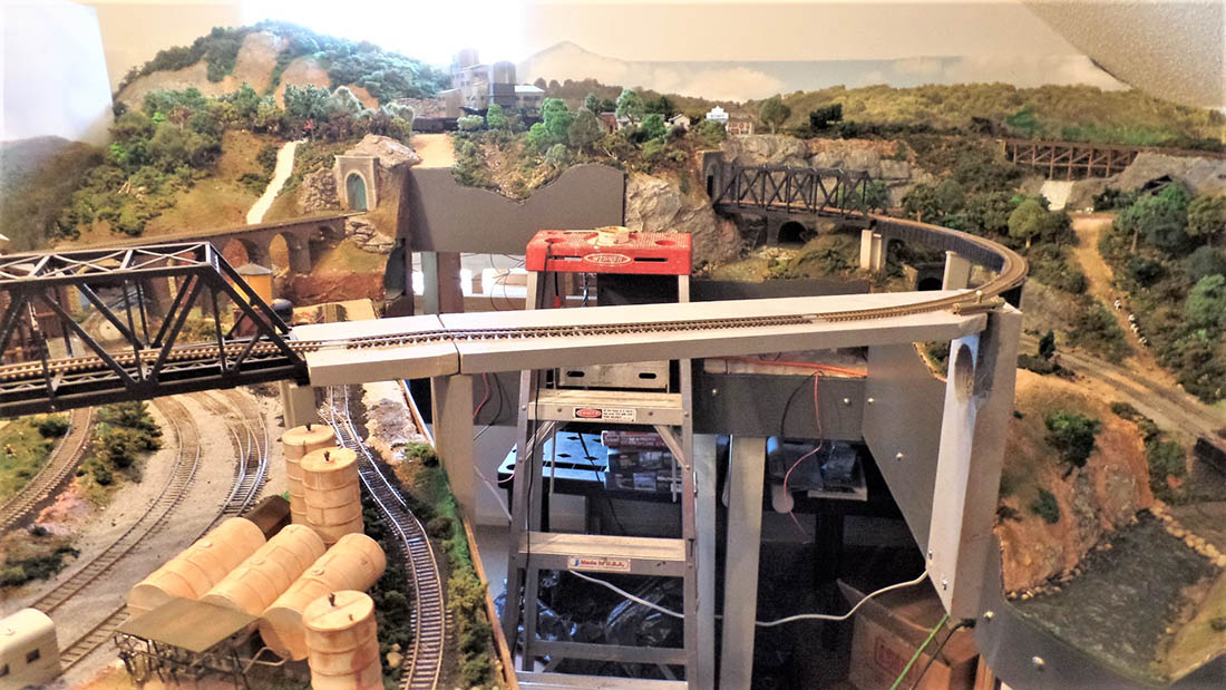
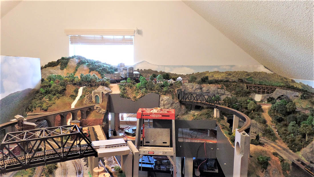
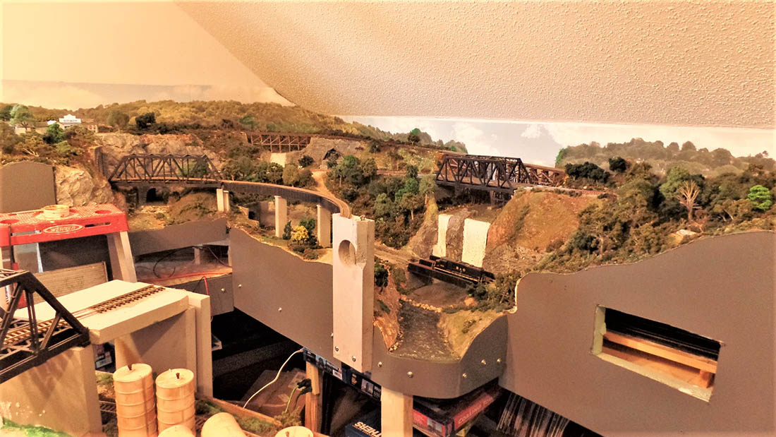
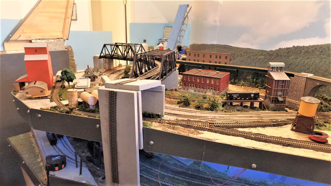
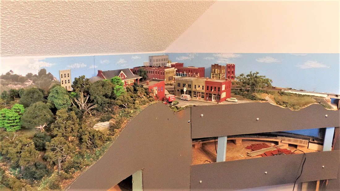
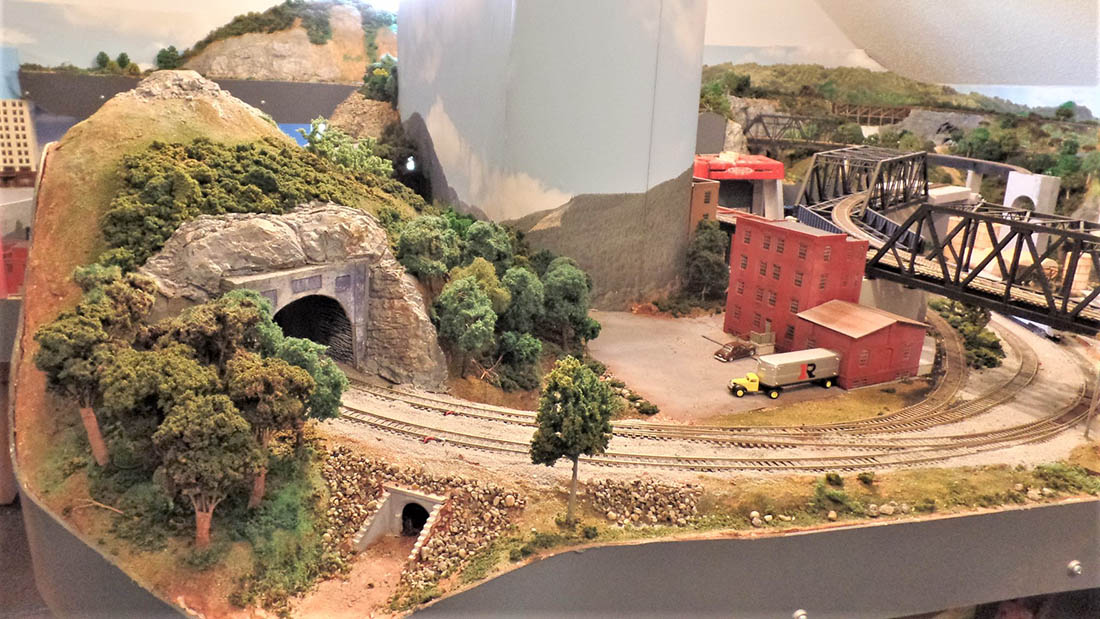
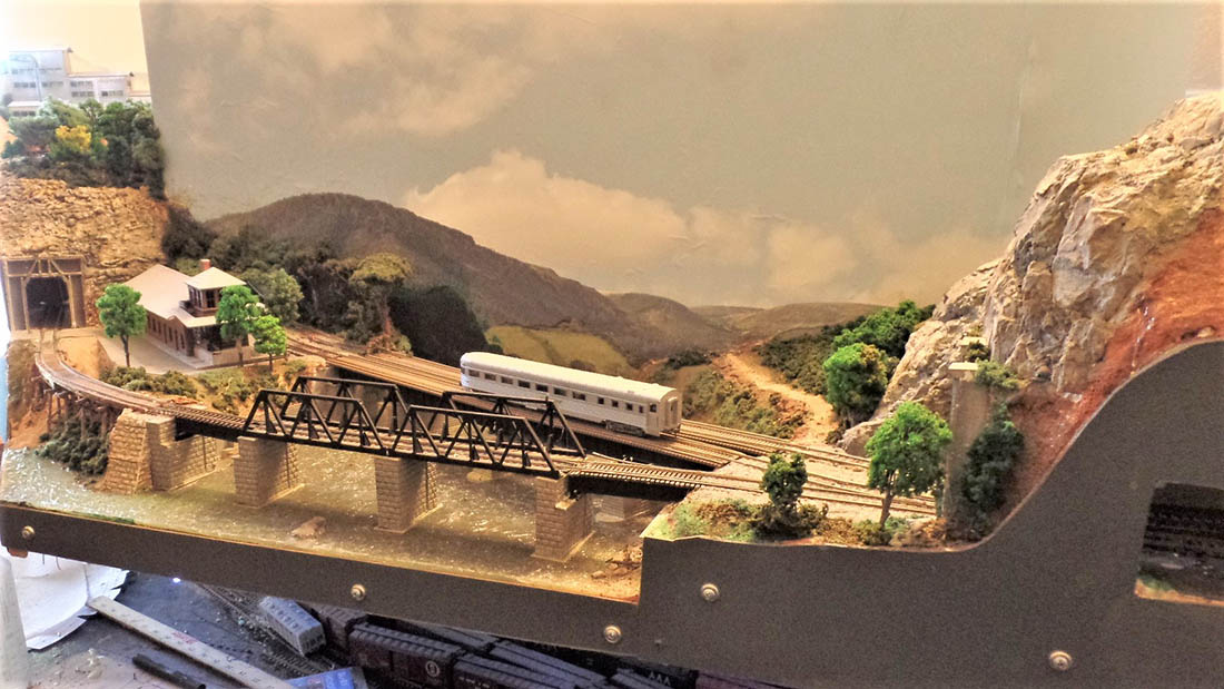
Here are final picks of a pretty but non functional layout before I start over. I hope to save some scenes in a functional plan. I will use all new track and DCC switches. No tables, max 2% slopes, no lift sections,etc.
Don”
A huge thanks to Don for sharing his model train tips.
(There’s more here if that’s your thing: Model train layout tips.
It just goes to show a little planning can go a long way, but in Don’s defence, sometimes the only way to start is to jump in with both feet. You might go wrong, but you learn quick enough.
Others plan and plan, but never ‘execute’.
Please do share your comments and thoughts on this below – I’d love to hear them.
That’s all for today folks.
Please do keep ’em coming.
And if today is the day you poke boredom in the eye, the Beginner’s Guide is here.
Best
Al
PS More HO scale train layouts here if that’s your thing.
Need buildings for your layout? Have a look at the Silly Discount bundle.