Peter’s been in touch with his Noch Baden Baden layout.
“Hi Al
Thought I would give a quick update to my layout.
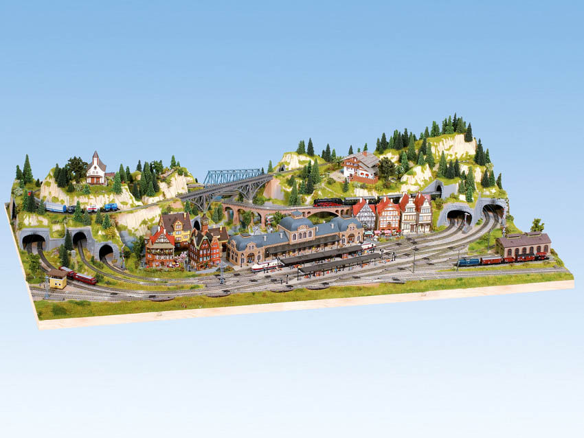
Still very much work in progress but thanks to the suggestions from your readers I am trying to attempt my version of Noch’s Baden-Baden layout (below).
I still need to purchase some extra ramps and finish building the mountains, but as you can see there will be a dual figure 8 track crossing the three mountains, with 3 double bridges (the 2 you can see plus 1 at the back of the layout).
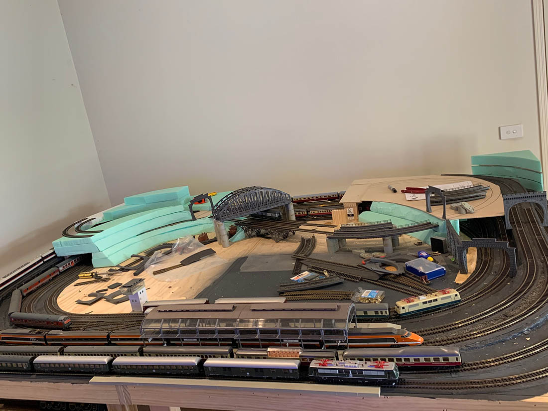
Here’s Noch’s version below:
Peter”
A big thanks to Pete – I’m always banging on about making a start, and Pete looks like he’s jumped in with both feet. Can’t wait to see an update on his Noch Baden Baden layout.
And now on to Ray, who has sent in the latest video of his layout:
“Hi Al,
Just a follow up from my last email.
I’ve created a new video which shows a majority of my layout. Running three CSX locomotives.
Thanks for all you do.
Best,
Ray
Massachusetts, USA”
Now we have a question, from Peter.
It’s also the very reason I started the forum.
Although Steve’s question is quite technical, in the forum, anything goes – from complete beginner questions, to very specific questions like Steve’s.
If you want to make that start, you really can ask about anything you like on the forum.
What’s more, as you’ve seen from the comments on the blog, we’re a friendly bunch, so please don’t be shy about asking.
Ask and get started!
Anyhow, back to Steve. Who can help?
“Hi Al
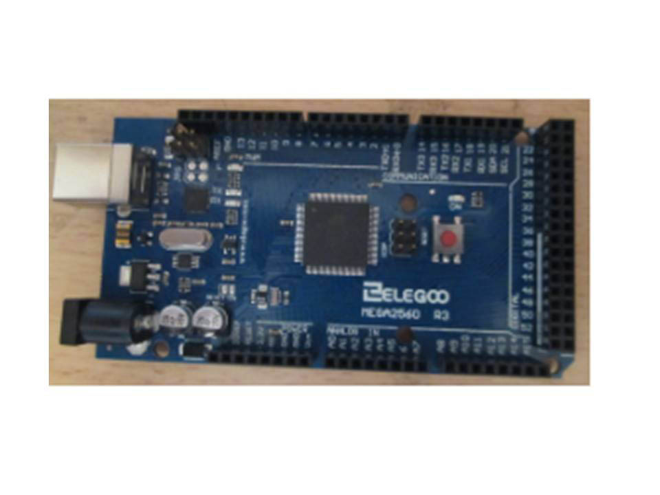
I wonder whether anyone out there is able to answer a couple of questions I have about using an Arduino?
It’s a microcontroller that you can program to work servos, motors, LEDs and so on. I am quite new to them myself (I first heard about them from a post on your site). I’m fine with the programming, it’s wiring the components that I’m having problems with.
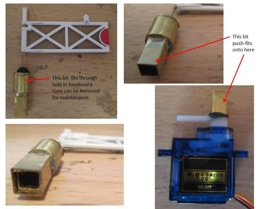
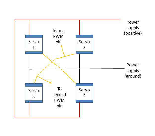
I am building a working level crossing, the older type used in the UK with gates rather than barriers. Each of the four gates is moved through 90 degrees by a servo. So far, so good, I have wired the servos up to the Arduino and written the code to make the gates open or close when I click a button on a remote control.
Each servo is connected to one of the Arduino’s output signal pins. At present that uses 4 of the pins, but as two of the servos move clockwise and two move counter-clockwise I think I can just use 2 pins instead of 4, with each of those pins sending the control signal to 2 servos. My first question is have I got that right?
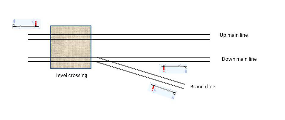
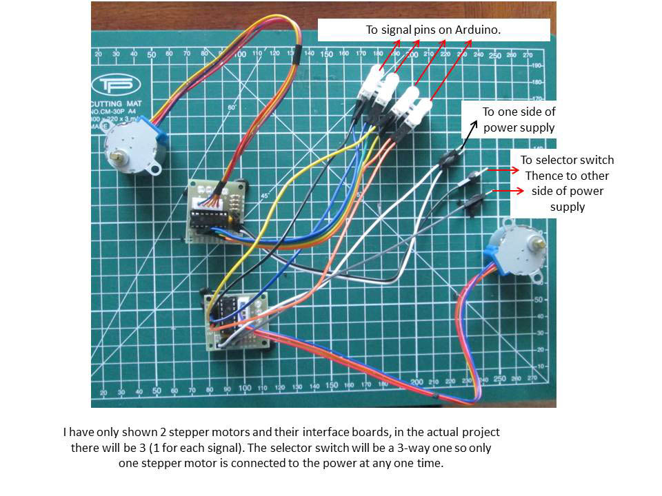
I have three semaphore signals (Up, Down and a single line branch joining the Down line) guarding the level crossing, which I want to control from the same Arduino board using stepper motors rather than servos, so that I can program in a nice subtle “bounce” when the signal arm falls to danger. Each stepper motor needs to be attached to FOUR signal pins, plus the separate power supply, and I want to be able to work the signals one at a time rather than simultaneously.
Now, here’s my second question. Can I wire the four signal leads from all of the stepper motors together and use something like a relay wired into the power or ground wires of the motors to select the appropriate signal stepper motor for operation? Otherwise I will be running out of Arduino signal pins (2 or 4 for the gate servos, 1 more for the branch point servo, 1 for the infra-red sensor for the remote control and 12 for the three stepper motors).
Thanks in advance
Steve, Lincs, UK”
If anyone can help Steve, please do leave a comment below.
Now on to something completely different.
It’s an email I get sent often. It’s old, but gold. It did make me chuckle the first time I saw it.
Here you go:

The U.S. Standard railroad gauge (distance between the rails) is 4 feet, 8.5 inches.
That’s an exceedingly odd number.
Why was that gauge used?
Because that’s the way they built them in England, and English expatriates designed the U.S. Railroads.
Why did the English build them like that?
Because the first rail lines were built by the same people who built the pre-railroad tramways, and that’s the gauge they used.
Why did ‘they’ use that gauge then?
Because the people who built the tramways used the same jigs and tools that they had used for building wagons, which used that wheel spacing.

Why did the wagons have that peculiar wheel spacing?
Well, if they tried to use any other spacing, the wagon wheels would break on some of the old, long distance roads in England, because that’s the spacing of the wheel ruts.

So, who built those old rutted roads?
Imperial Rome built the first long distance roads in Europe (including England) for their legions. Those roads have been used ever since.
And the ruts in the roads?
Roman war chariots formed the initial ruts,which everyone else had to match for fear of destroying their wagon wheels.

Since the chariots were made for Imperial Rome, they were all alike in the matter of wheel spacing.
Therefore, the United States standard railroad gauge of 4 feet, 8.5 inches is derived from the original specifications for an Imperial Roman war chariot.
In other words, bureaucracies live forever .
So the next time you are handed a specification, procedure, or process, and wonder, “What horse’s ass came up with this?”, you may be exactly right.
Imperial Roman army chariots were made just wide enough to accommodate the rear ends of two war horses.

Now, the twist to the story:
When you see a Space Shuttle sitting on its launch pad, you will notice that there are two big booster rockets attached to the sides of the main fuel tank.
These are solid rocket boosters, or SRBs. The SRBs are made by Thiokol at their factory in Utah.

The engineers who designed the SRBs would have preferred to make them a bit larger, but the SRBs had to be shipped by train from the factory to the launch site.
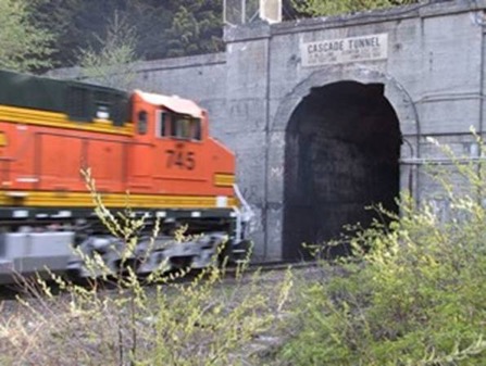
The railroad line from the factory happens to run through a tunnel in the mountains and the SRBs had to fit through that tunnel.
The tunnel is slightly wider than the railroad track, and the railroad track, as you now know, is about as wide as two horses’ behinds.
So, a major Space Shuttle design feature of what was arguably the world’s most advanced transportation system was determined over two thousand years ago by the width of a horse’s ass.”
That’s all for today folks. Please do keep ’em coming.
And don’t forget the Beginner’s Guide is here if you want to get going on your own layout.
Best
Al

Steve, Lincs, UK; Answer1: I think the simple answer is yes, but you need to watch how much current is driving 2 servos in parallel. What about using servo & motor controllers?? These controllers use there own power, so they should be able to run 2 servos each. Answer2: same as answer1….Google your q’s, there is tons of stuff out there for Arduino!
Steve, Sydney.
It is possible to do ‘bounce’ with servos – MERG do a kit for a servo control board with programmable bounce, so it should be possible to ‘bounce’ a servo from an Arduino.
Ray’s layout is superb. I love the sense of space with trains running at realistic speeds. For me, too many layouts are cluttered with too much track in too little space. The details are excellent. Well done.
Thanks for that.
I intend using external power for any motors/servos as I know the supply from the Arduino itself is a bit feeble.
I did ask Professor Google about driving multiple servos/stepper motors, but all I could find were situations where people wanted to drive a number of servos/stepper motors simultaneously, and none of them mentioned how to physically connect multiple motors! I kind of assumed that my concept of sharing pins was how to do it but thought I would ask on here.
Thanks again for your help.
Steve – if you’re concerned about the number of inputs you can expand the arduino’s output by adding multiple adafruit 16 channel pmw boards. I have three of these connected to the same arduino that you have and have control over about 30 servos for point motors. You should be able to do the same with your servos and stepper motors. A little bit more programming but you can put them at different places on your layout and use less wiring.
Thanks, Tim, very useful.
Really enjoy seeing all of the different layouts, but was wondering why in all the ones I have seen why I have never seen a small dirt stock car track . I think that would make an interesting piece of scenery. Keep up the good work, love watching the trains roll…..
RAY, Great layout video . Kept me enthralled . now as for the mountain lift that one car made me sea sick, lol. Good job sir.
The Critic
@Barry Hess My guess would be for the same reason you don’t see many sports stadiums, circuses, etc modeled in general. Takes up too much valuable real estate for a single static scene display that can be otherwise used for running trains.
I just love the chariot-to-rocket booster story! It also goes to,show the importance of taking a 360 degree view of product development! Reminds me of another railroad “lesson”… I was involved in the implementation of optical fiber networks in the US in the mid80s. For continuous access we secured Right Of Way from railroads. During a meeting with Amtrak and CSX engineers we were attempting to place the fiber lines 10+ feet from the rails fearing derailment damage. The railroad guys insisted it be within 5 feet. One of our engineers declared “but you don’t know anything about the telecom business!” …to which a CSX engineer responded…”clearly you don’t know anything about the train business because when a train derails, it usually lands about 10’ away from the rails”.
Cheers, Mike in NC
For Steve
I agree with the comment re beware not to use too much current through each output. You might be better to consider buying An arduino mega they have masses of output or input pins. Alternatively add a motor bridge some even have output pins ready for stepper motors
I’ve used a mega and motor bridge with a raspberry pi to run dcc
I love the horses ass story. It could almost be a Budweiser commercial.
Thanks, Al, for the history of rail spacing. Never saw that before.
Thanks for the rail spacing report. I actually have the Roman story in a frame on my wall because I have been asked that same question many times. The space shuttle tanks was is an interesting addition.Ray, great layout and wonderful video. How large is that layout?
Yea i am going to make a space on my train board for the space shuttle.
MERG do have an Arduino SIG group.
We Zoom meet every other Wednesday at 7:30pm GMT that’s 11am for us on the Pacific coast. MERG also have many what they call pocket money projects that you can build for pennies. Great club with lots of great help well worth joining.
MERG = Model Electronic Railway Group.
Granted I know little to nothing about Arquino tech but have you considered running the Aquino out through a relay, electronic or mechanical, to switch on higher power?
Al … thanks for the railroad gauge story …. made me laugh …. made me cry, a whole lot of emotions passed through me as I read ‘Logic 101’. It would be interesting, a full time job for scores of people to search the internet, and find similar stories for probably everything man has ever conceived.
Steve, As all have said the short answer is “yes” The control line on the servos is high impedance so hooking a couple in parallel works fine. Just to be sure I ran a quick test with 2 servos and a Raspberry Pi. I can’t speak to the stepper motor question. I chose to use servos for semaphore control.
From your picture I see you are using a Arduino Maga, which as Roger noted have 54 digital pins + analog (16?) plus. But there are never enough are there!
In my setup I use an Arduino Maga w/ a Motor shield as a DCC++ base station with 36 IR sensor attached and two outputs controlling relays for track reversing. The motor shield provides the DCC signals to the track. The DCC++ controls the trains and turnouts and monitors the sensors in the track. I also use a Raspberry Pi with several HATs (Hardware Attached on Top) to control 56 semaphore arms, monitor the state of the turnouts and control 12 LEDs for 3 more signals.
That was amusing.
In the maritime world, submarines had an anchor that was never used. Why an anchor? Because all surface ships have anchors so a submarine had to have one also or it wouldn’t be a ship. I’m not sure, but I think the modern nuclear subs have done away with anchors.
Thanks for the very true story!
Steve, I have only speed read your e-mail, but I will give you one strong suggestion. Go tou-tube Little Wicket Railways. This guys instruction on Arduino and Servos are BRILLIANT. In particular there are 3 on servo’s (points and signals). Also more stuff on detection etc etc. The firts video is: https://www.youtube.com/watch?v=ayOoUkdjHtg&list=PLBf9xPI6yiapAtW_Dbm7qQwzt-7eEhN2-&index=6
He uses a servo control card hooked up to the Arduino. The card is a PCA9685. Its much better if you just look at the videos. There is code you can down load as well
Love the layout Ray – cable cars, fair, circus – brilliant! Very lucky to have so much space to build.
Brian
Wokingham, UK