Andrew’s been back in touch with a great step-by-step on model train street lamps:
(Last time, he showed how he made his signals.)
“Hi Al
Firstly, I must compliment you on a stunning site full of the most useful tips and instructables.
But I don’t want to be a taker and not offer something in return, however, modern technology and I don’t always sit comfortably around the same table so I am unsure as to how to submit my little offering.
Living in South Africa with a most unfavourable exchange rate makes the railway hobby more challenging than it is for our counterparts in Europe or the Americas so necessity becomes the mother of invention and we have to find affordable alternatives.
So being old school and not following the DCC trend, my objective has been to develop cheaper methods to achieve similar ends within affordable limits.
Toward that end, I have devised a couple of low cost systems and include one here that if you think it is a worthwhile addition, please feel free to distribute it as you see fit.
Thank you once again for your superb contribution to the hobby and may it continue for years to come.
I am sure that we all cruise the internet of things looking for effective ways of producing items for our layouts.
I was lucky enough to find a youtube video which provided the simplest method that I have found so I don’t take the credit for the idea but pass it on in written format for those of you who wish to use it.
For those of you who would prefer the video link, it is below:
Latest ebay cheat sheet is here
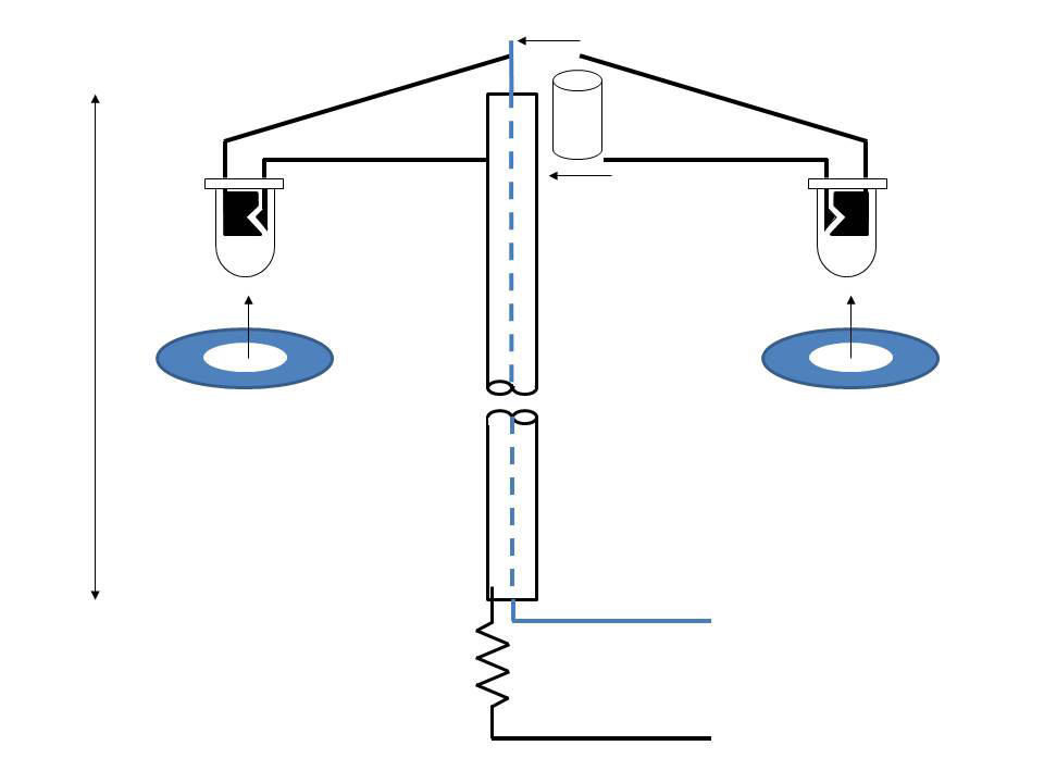
I found the parts for the model train street lamps to be relatively easy to source locally. Below is a sketch of the assembly:
I found that the most difficult part of the exercise was drilling the 3mm holes through the brass paper binders (You can get a box of 100 for about R35.00).
Firstly, they are not brass but brass plated steel. Secondly, being so small and smooth, how the heck do you hold them without causing damage?
Trial and error succeeded at the end of the day and I was just thankful that I did not need to make too many of them.
So, what do you need to make these lights (and of course, you could make single lamp types just as easily)?
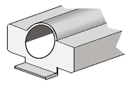
2 white LED’s 1 ±800Ω resister 6 -8mm of heat shrink ±90mm of 2.5mm brass tube 2 paper binders A whole heap of patience.
• Open the paper binder pins outward and cut off leaving approximately 2mm of each pin
• Press the paper binder into a piece of soft-ish wood and drill the 3mm hole (I suggest start with a smaller drill and work up to a 3mm
• Remove the paper binder head from the soft wood and trim off the remainder of the “legs”
• Now bend the legs of the LEDs to the desired shape remembering that the anode leg (the longer one) is to be soldered onto the pole
• Bend the anode leg around the pole and solder into position making sure that the cathode leg terminates approximately 3mm above the pole
• Slip a piece of thin wire (once again, I use CAT5 network cable stripped down to individual pairs) up through the brass tube
• Pop the heat shrink onto the end of the pole
• Solder the wire to the cathode leg of the LED and shrink to a tight fit
• Solder the resister to the INSIDE of the base of the pole
• Attach the “lamp shade” made from the paper binder with a drop of super glue
• Paint to the desired colour remembering NOT to paint the LED or the inside of the paper binder.
• Drill a hole in the base board or platform and connect …. As easy as that, your model train street lamps are done.
One could (I suppose) call me a “Colonial”, but I only discovered many years into my model train adventures (obsession) that my great-great-grandfather heralded from the city of Bristol and quite coincidently, the bulk of my collecting over the years was the GWR.

Not realizing the full extent of the task, I had in my ignorance embarked on the program of building/ collecting as many of the GWR locomotives that I could. In my research, I discovered the wonderful GWR.ORG site (http://www.greatwestern.org.uk/loco_draw.htm) which provides many drawings of the GWR locomotives and has become an indispensable tool in the objective.
One such sample was the 15XX class 0-6-0T which I tackled as follows.
Firstly, with the use of Photoshop, I scaled the drawing to 1:76 (OO).
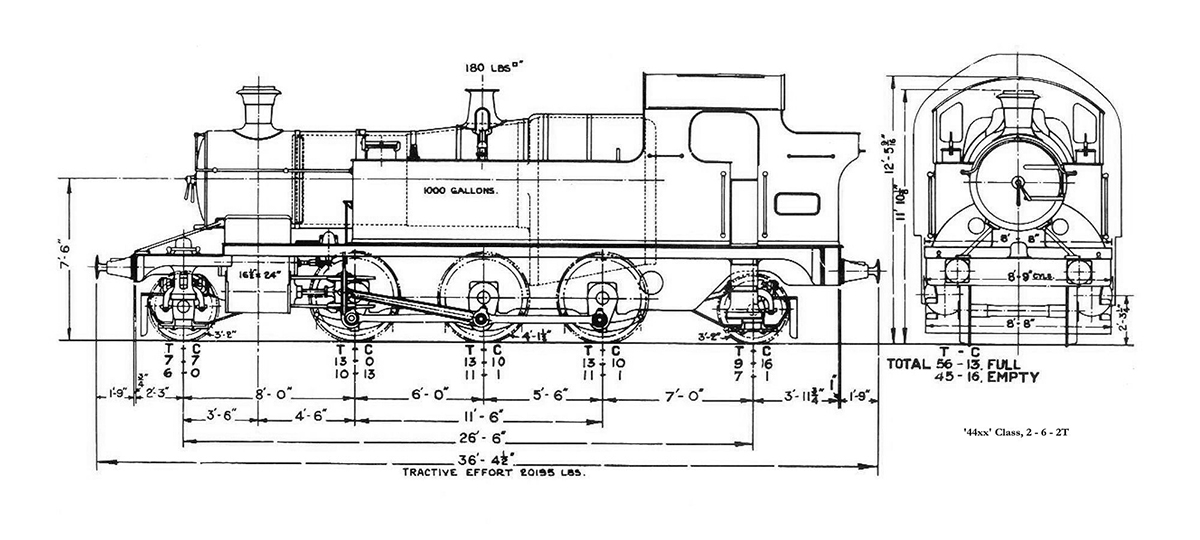
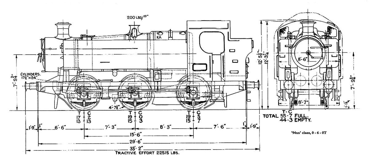
I then went looking for another loco drawing the approximately fitted the required dimensions and discovered that the 44xx Class 2-6-2T had about the right wheel arrangement. In similar fashion, the 94XX Class had a body that could be modified to resemble a “close-enough” fit.
Armed with this information, I climbed onto eBay in search of an unwanted sample of each and was lucky to get both of these Lima models at roughly the same time for approximately £8.00 each and with the unfavourable rate of exchange, took the plunge with scant concern for my bank manager’s reprimand.
With excitement bubbling in my brain and an itch in my hand to grab a scalpel, I went AWOL from work and rushed to my workbench where I immediately stripped the 44XX Class down to the chassis (Carefully storing the body for a possible future conversion) and removed the front bogie and rear truck.
Similar treatment was given to the 94XX Class with the chassis being stored away and the body was test fitted onto the 44XX Class chassis to determine how much cutting/building was needed.
VOILA!!!! Very little so the project was to go ahead at “full steam”.
Remember that constant reference to the drawing(s) will be necessary throughout the process. Putting the chassis aside, my attentions turned to modifying the 94XX Class body. Remove the water filler caps and other loose fittings from the top and sides of the tanks and store them safely for later use.
MODIFYING THE 94XX CLASS BODY
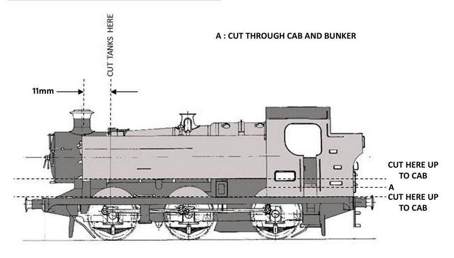
Having scaled both the 15XX Class and the 94XX Class with Photoshop, I was able to superimpose the one image over the other and this clearly displayed what and where to cut.
The tanks on either side had to be shortened by 11mm and every attempt must be made to preserve the front face of the original tanks which are shaved off and re-glued onto the shortened tanks.
Remember that the thickness of the front face material must be factored into your calculation. This will retain the correct image of the shortened tanks. I used a scalpel with a No 10 blade for this exercise as well as a number of band-aid plasters for when the scalpel enthusiastically slipped. Tamiya putty hid all the mistakes rather effectively.
Now, if you are not feeling brave, you can cut right across the tanks and the boiler and fit the loose smoke box from the 44XX Class.
Although not entirely correct, places the chimney a little too far back and renders the original 44XX Class body almost useless, it certainly is the easiest option.
The alternative is to cut the tanks away from the existing boiler and fill in with styrene sheet and Tamiya putty. This is largely dependent on your modelling skills and confidence. When cutting away the footplate, keep a small section of footplate in the centre to fit under the smokebox of the 44XX Class chassis.
Next is the section below the level of the tanks. Once again there are two options.
Firstly, for simplicity sake, remove everything below the tanks up to the front of the cab. Where visible, cover the front of the cab with styrene sheet sections cut to shape allowing clearance for the motor and glue in place. This leaves a cab side that is a little too tall and not prototype accurate but does allow for easier fitment to the 44XX Class chassis.
The second (and more accurate method) is to cut everything below the pannier tanks away. It is important that a straight line cut is achieved below the cab and coal bunker. I achieved this by lining up a steel ruler with the bottom of the tanks and scribing a line through to the rear on both sides of the cab/bunker and then joined the scribed lines across the rear.
The initial cut was achieved with a cutting disk on a dremel leaving approximately 0.5mm material below the line and the balance of the footplate intact. Holding a piece of 180 grit sandpaper on a flat surface, this additional material was sanded away to achieve the straight line.
Cut away the foot plate in front of the “Cab” line as well as the excess material above the foot plate from the original cab. Smooth this down using 180 grit sandpaper on a flat surface as per the above. (note that as you will have two very thin and flimsy sections of footplate, it will be easier to perform this operation before you cut away the front section).
Once you are happy with the result, glue into place below the cab and fill in the necessary areas with styrene sheet. You will also have to cut away and either increase the height of the rear buffer beam or make a new one to fit.
The downside of using the second method is that a substantial portion of the motor and its workings will be visible but this can be hidden with the fitment of some styrene sheet from your scrap box and painted matt black in the final stages.
Irrespective of which method is selected, a 2mm thick piece of styrene sheet from your scrap box must be fitted across the inside of the bunker for mounting onto the 44XX Class chassis and the position is determined by fitting the body to the chassis. The same fixing hole on the chassis is used for this purpose.
MODIFYING THE 44XX CLASS CHASSIS
Apart from removing the bogie and the pony, not much is required here. Fortunately the front buffer beam is part of the chassis and can remain as is. The only modifications that I did was to remove any rounded chassis bottom sections which curved around the pony and the front bogie.
FINISHING TOUCHES
The 94XX Class body has recesses for the water filler caps that are cut away when shortening the tanks. In order to replace these, the recessed portion of the caps are cut/sanded away and then the caps are glued in position. New holes are drilled for the hand rails and these are re-fitted.
Depending on the era you are modelling, the body is then painted in GWR green or BR black and the applicable decals are applied.
CONCLUSION

That is about it guys. I have picked up that I made a few mistakes which are to be corrected. The body line on the cab is too low and I have not yet finished the little touches including the repair to the front buffers.
Depending on your modelling skills and attention to detail, I am sure that much more can be done to your model.
I concede that there are probably a number of errors that our rivet counters will comment on but the model is a “good enough” representation of a 1500 Class produced on the cheap.
The alternative would be to purchase an expensive brass etched model and have MANY more hours of enjoyment in the process. I am happy with my results and I hope this will provide some inspiration to at least one more enthusiast.
Andrew”
My word – a huge thanks to Andrew for sharing his model train street lamps, and his loco builds too – what a wondeful project.
I think the older we get, the less we use our imgination and creative skills, but Andrew proves they are still there if we put our minds to it! So it got me thinking – please do leave a comment below if you’ve bashed anything in a similiar fashion.
That’s all for today folks.
Please do keep ’em coming.
And don’t forget the the Beginner’s Guide is here if you wan to take those first steps on your very own layout.
Best
Al