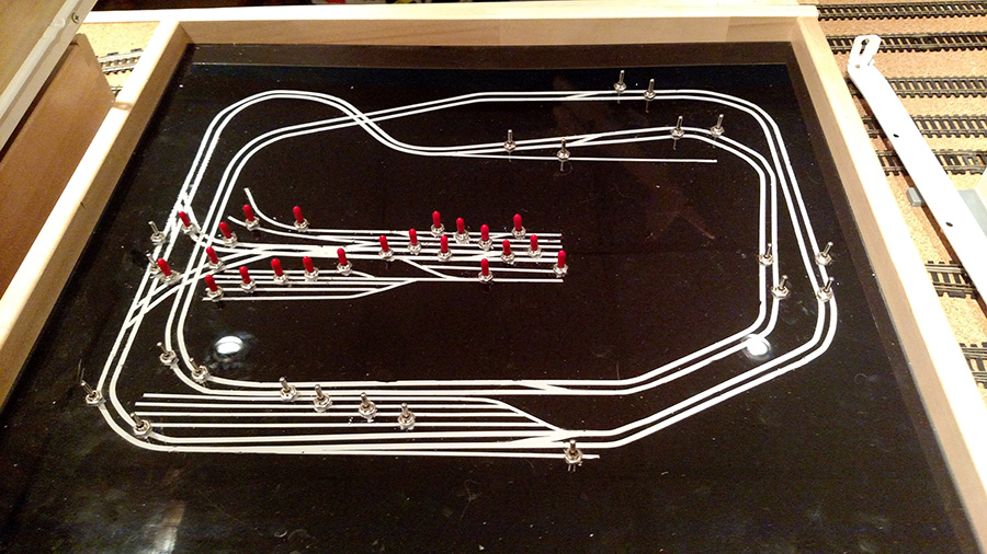
Michael’s been in touch with a wiring question – HO scale wiring terminal block.
As usual the comments at the bottom of the page all seem to have identified the issue. Have a look and you’ll see what I mean.
What a clever lot you lot are.
“I’m looking for someone to diagram a wiring problem that is beyond my ability.
My railroad has 4 cabs ( power supply ) 2 for the main lines and 2 for the yard.
Cab A and B are main lines. C and D yard.
I want to be able to use can A to bring a train into the yard without stopping at the meeting point. Then switch to cab C or D once in the yard.
Can you help?
Michael”
Please do leave a comment below if you can help.
And now on to Dave.
I know I post a lot of Dave’s stuff, but the problem is, I watch it, enjoy it, and then I think “I should post this.”
So here you go, another one from Dave:
“Hi Al, well with a couple of days of the weather cooling down, I went back up in to the loft and decided to make a few changes …yes changes from Dave ??
LOL ..it’s what we do though ..all for the better though, new platform, giving me more space to add an extra siding, and some bridge changes, giving it a better look than before…
seems to have worked… added a little running session as well.
Regards
Dave”
Latest ebay cheat sheet is here.
A huge thanks to Dave – and who can help Michael? Please scroll down and leave a comment below if you can.
And don’t forget today is the last day to grab this very silly deal on the print out scenery.
Course, I’m biased, but they are great fun – and a good way to make a start too.
Please leave a comment for Mike below if you can help on his HO scale wiring terminal block problem.
That’s all for today folks.
Please do keep ’em coming.
Best
Al

Michael,.it sounds like you need to power one section of track from to power supplies (cabs). Easy, install a double pole double throw (DPDT) switch on that section. You wire the track to the center tabs, and one can to each end tabs. The switches usually have a diagram on the package.
You must also separate that section of track from the rest of the layout by creating insulation gaps in both rails at each end of the section. Best done between two turnouts.
On my phone, so I can’t give a diagram, but I’m sure another of Al’s followers will be able to supply one.
You don’t say if you are using DC or DCC, but from the terminology I’m assuming DC. I’ve Used rotary switches (4-pole) with each cab back when I was in DC mode. If you have common return wiring you only need single way switches. If not, use 2-way. Wire each cab positive to the same position on each switch (you can daisy chain the switches). When you want to drive from one section to another, switch the involved sections to the controller you want to use, e.g. bringing a train from section 1 to section 5 and crossing section 5, just trace the route and turn any section switch to the cab number you wish to drive with. Hope this helps. Join
In any case Cab A and Cab C will have to be set to the same speed and direction. Then it won’t stop at the crossing point. I fail to see the problem.
I am guessing that your problem is that of a polarity mismatch, If so there is a device called an ARSC (Automatic Reverse Section Controller). It was produced by Loy’s Toys which is now out of business. Fortunately there are usually a few to be found on Amazon or Ebay.. The ARSC will reverse the polarity of a section of track by sensing the incoming polarity and comparing it to the out going polarity and then correct the out going polarity without any human input. They work great. I am using 2 ARSC’s on my layout to get around polarity mismatches. It ia an incredible bit of circuitry.
The simple answer is to go dcc then you can drive everywhere on one controller.
I assume that there is an isolated track separating each section so the way forward is to add a switch to turn off power to the yard and a pair of wires to jump the isolation with a switch the switch you want is a double pole centre off to avoid short circuits. To avoid short circuits it would be best to make sure there is a common return too that is the power is to the same rail from each controller. This should allow an uninterrupted drive through from mainline to yard. An alternative would be to create an additional isolation point with a switch to energise in fact a switch at each end ideally with a signal working in conjunction for realism
If you search Brian Lambert 00 gauge electrics you’ll find a fantastic web site with diagrams which will help you and anyone else with questions on circuits track Laing etc
Good Luck Roger
For DC use a section of isolated track fed from the ‘mainline’ by a resistor and rectifier and fed from the ‘yard’ by a rectifier (and maybe a resistor). A relay may be needed for reversing this arrangement if the direction of travel is the other way round.
Dave’s layout was most excellent as always, way advanced on his productions. As nothing looks familiar with U.S. so is really unique to myself.
I would use a double pole double throw switch and miniature relays. You would have to: 1) Switch power supplies so one or the other would actually be feeding the other circuit. Must completely isolate each circuit with switch and one would be temporarily powering the other circuit.
2) Pending on polarity of either transformer unless done as such direct short can easily occur.
3) Track of coarse would have to have double insulation as one power source or the other would be temp feed for other.
4) Needs of coarse to be short circuit proof easy done with switching and isolation of relay contacts.
5) Of coarse polarity still needs be monitored or train may run backwards after switch, but nothing smoking. Pulling into a yard in real life is never a single none stop move anyways; at least as the St. Lawrence & Atlantic does the move, even on main lines in Auburn, ME.
Other ideas are also doable, how did anybody survive non DCC era anyways?
Regards, Rich
You have to make a block where you are going to make the switchover. An off and on switch from each of the cabs. Enter into yard cab A switch on. then off then turn on the yard cab, that switch was off when you entered yard. Watch the + & _
When I had 4 cabs controlling the railroad in DC I used (two pole, four throw) rotary switches. the two center tabs went to the track, and the outer tabs were connected to the power supplies.
That said, I converted to DCC as fast as I could.
Hi Michael,
I like the DPDT switch solution but was wondering if all of your transformers are phased together. Run a wire to the negative terminal of ALL of the transformers.
question for Dan Smith. Did the ARSC have a schematic? Can a picture of the board or wiring be provided? I searched for Loyd;s Toys and ARSC and didn’t get a hit.
John Frye
Hy dave, I have a different idea. I would buy four 10 ohm wire wound 20 watt resistors and connect one to one side of each cab. I would ty all four other sides together in a common ground. Then I would add one rotary switch per track section that can select any of the cab resistors. That way you can power any or all of the tracks from any cab. You want to avoid having adjacent tracks on different cabs. Only turn a rotary switch when an engine is clearly in the new track section. The ten ohm resistor should not effect an engine much. I would suggest you change to Dcc and eliminate the whole mess. Good luck.
Where can I find Brian Lambert’s OO gauge electrics info. Can’t get a hit on Safari.
how many hobbies or interests would have the response as this one? switching off from the news, it’s great to be among friends.
DCC is not inexpensive but makes running our trains 🚂 so much more more fun.
Hello Michael.
I use the old DC means of running my trains. My main line has 4 separate cabs / sections. I use single pole switches to power each cab. I have a dual area that is a little more in length than any of my locomotives. This area of track is insulated off from the other track and is controlled by the switches. Of course, I have to stop the locomotive for the change of power but it can all be done with 1 power source.
I hope this gives you an idea of what can be done.
Robert Ramsey
Hi Michael, I belong to a local model railway club here in the UK. We have a 60feet by 6 feet layout with two main lines, two separate sidings and a branch line. All 5 sections are connected with isolating fish plates and controlled by 5 gauge master controllers, when driving trains I just make sure that the section I am driving into has the controller set at the same level as the one I am leaving. We also have all of the main feeds into each section passing through dpdt switches so that we can switch sections to a lenz dcc controller. This allows us to run dcc and analogue trains on different parts of the layout at the same time.
Hi Dave, living up to your Dangerous nickname there mate, those platforms are waaay too narrow, you want a good six foot from the edge of the platform to any obstacle like a building or footbridge, call it an inch in OO. Remember in slam door days how trains would barrel cheerfully into stations with people swinging doors open ready, before it had stopped? Had to be able to get out the way. If short of siding space, have you seen Bristol TM? There are two carriage sidings in between the main up and down platforms. All the best,
Rod
Ken has the answer!. Double pole double throw switch.
insulate the track, use a relay, NO to C, NC to A. Control relay with a SPST switch, (off=A, on=C) or other device such as a photo eye placed at switch over point. Power relay from a switch or photo eye at end of “C” that removes power when actuated (switching entry to “A”) Be sure to have a main switch to disable entry if line is full. Hope this helps.
Hello Michael. On my layout which is all dc controlled I use a selector switch. Go to Train sets only web site and check out the Atlas selector switch #150-125. This is what I use to control power blocks with different cabs as in entering a branch line from a main line. Once the train enters the branch line a simple flip of the switch(s) and the branch line is then controlled from a different cab. This switch allows control of a single track or power block from 2 different cabs. Hope this helps.
Ken from PA, USA
I am running 8 transformers on my layout running trains from one to the other without a problem. (I run 1960’s marklin AC trains). If you tie the grounds together as the common you can connect the positives of the transformers together with 1N4007 diodes. The diodes will isolate the positives from each other and one or both supplies can then provide the power.
Louis
Cape Town SA
Brian Lambert is at https://www.brian-lambert.co.uk/
Simply, you need to have an isolated section to avoid shorts between controllers. And you need to switch from one controller to the other, preferably while the loco is stationary in that transfer zone.
I do wonder if commoning the outputs would benefit, since it depends on the isolation of the controllers, and so might not be something you can generalise about.
Hello Michael, Consider DCC.
1- With one Decode you have a choice of 9999 locomotive numbers.
2- With a 5 amp DCC supply you can run 5 Sound locomotives, all at the same time, and each locomotive can have a radio Speed and Sound controlled throttle with any locomotive number!.
3- With 4 DCC Circuit Breakers, you have your Main A & B, Yard C & D area for a short circuit area, for any train, or all the trains up to 5 Amps in the same area.. (Each breaker as two wires in; and two wires out. The 4 wires (one of each breaker) to a common ground is NOT acceptable, because you have a reverse loop in your layout. Your A,B,C, & D areas now must have insulated on both rails. Special circuit breakers are now need to first change the track polarity when there is a 7 amp short.)
Bob Frey
There are at least two manufacturers of auto reversing current circuit boards here in the US that will work regardless of DC or DCC operation. One manufacturer is Digitrax, which is mostly DCC oriented but the AR works well with DC. AND isolated section of track should solve any issues.
Norm in York PA
Ken has the simplest answer
I use three cabs on DC and can drive a loco anywhere on the layout from any controller. This is through the use of three rotary switches. This avoids matching controllers etc. My system is a standard on and allows three locos to be moving at the same time e.g. outer main, inner main and yard. I could explain in words which would probably be unintelligible but I do have a couple of diagrams which illustrate the wiring but cannot seem to attach them here. With an email address I could send them. My system is one sent to me by Kent Panel Controls for which I am truly grateful!
Dave you amaze me with all your changes and additions they really look great. From South Florida. Ron Nelson
Hi Rod , yes it would make more sense if the buildings were in size with the platforms , the one i did before was too wide as was the metclafe building , the pre set Hornby platforms are too narrow to be able to sit a ready build building on them , the way id did it though has given me extra siding , so maybe I shall have to search for a very narrow building …..As for Michaels query …it is difficult trying to isolate , best way and one where you run as many as you can fit is with DCC …the only way these days ….Dangerous Dave
Hellp Al..Thanks for being you!…RE: dc switching problems.. Being a retired
industrial electrician, I’ve seen a lot of “solutions ” If you are interested in
realistic operations, the only way to fly is with dcc. As you know, all locos
are independant with one fixed voltage power supply for the whole layout. It
all depends on what is your priority and how much money you want to spend.
Regardless of which way you go the main reason is to enjoy your work and to
keep your wife happy. RJL
I have been working with DCC for about a year now, I’m not sure I will continue. The convenience of not having to switch blocks as a train progresses is great, but if you have dedicated loops, there’s not much advantage.
I have 5 DCC locos, totalling about $900.00. They don’t really work that well. I could have spent half that for DC. The only trouble is, that model wasn’t available in DC only when I was shopping.
I also have a dozen DC locos that won’t run on DCC.
If you are just starting out, it might be worth while trying DCC.
I’m still not sold. Even for sound.
yard feed using 2 double pole/double throw center OFF switches. Yard must be isolated from Main line A .Wire center of one switch “A” to the yard. Wire one side of this switch”A” to the center of second switch “B”. Wire the second position of switch “A” to cab A. Wire cabs C and D to the second switch input positions.DONE To enter the yard use sw”A” to select A Cab Drive into yard, move swA to the other position and with swB select desired cab for the yard. To leave the yard simple place swA to the original position.