There’s lots of model train shunting layouts on the blog, and Hall of Fame Brian’s is one of those.
This time, he’s made some improvements – he also hit on something that comes up quite often, and that’s how small, simple changes can have a big effect on a layout:
“Hi Alastair,
I was looking at the upper level of my layout last night and decided that it needs some refreshing in one of the corners on the upper level to improve operation.
I found that while doing some shunting to the stock pens, I had a small problem in seeing them because they were partially hidden from sight. Remember that the top level is almost at eye level.
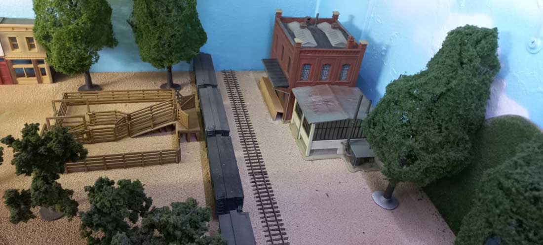
By moving the stock pens to the opposite side of the track and the building (an industry) rotated it 180 degrees to where the stock pens were, the operator now can see where the stock cars / rolling stock need to be placed or collected.
Fortunately everything had not been fixed down yet so it was easily moved and is now ready to be placed in the ground cover.
Even the trees in front were moved for a better line of sight from the operators viewpoint.
It is amazing how something so small can improve viewing the layout and operations.
Here are a few photos of the corner section showing the before and after the move.
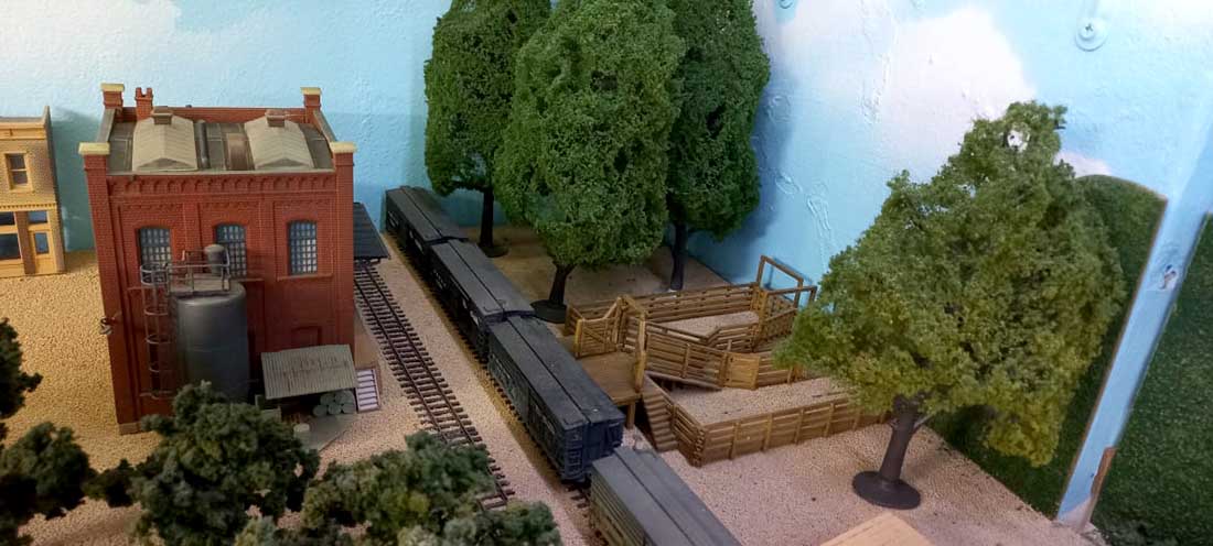
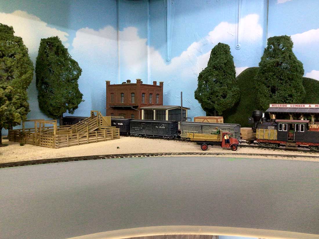
Before moving the stock pens and the industry. (photos taken while standing on a step ladder.
This is a simple move shown below as I had not bedded the buildings into the ground.
Here a check is being done to see that all rolling stock clears everything.
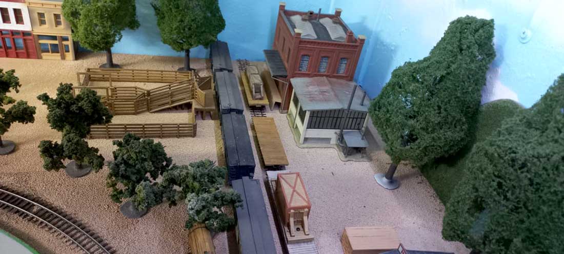
A view from above.
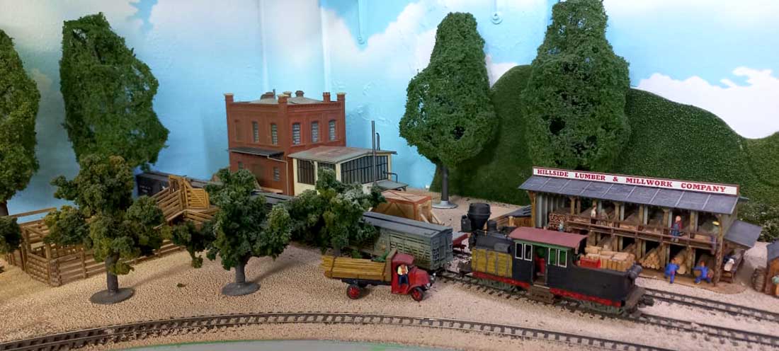
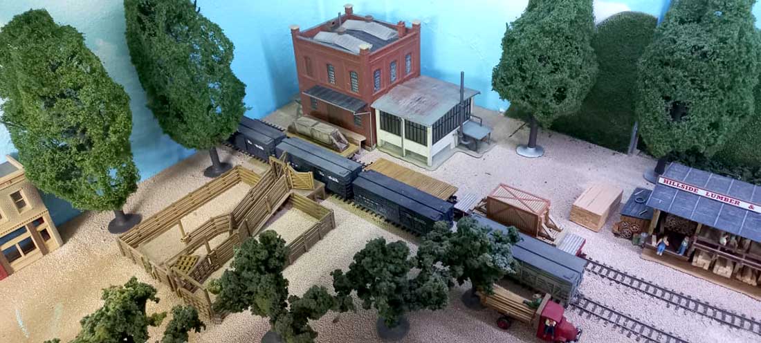
Almost an eye level view.
A few small bushes and grass as well as some stray cattle and sheep need to be added here to finish the scene below taken at operators level.
There is enough room in front for a farmer to bring in his heard of cattle or sheep to the stock pens ready to be shipped out by rail.
Now my fellow operators (me included ) cannot complain about not seeing the track for car placement or pick ups.
That’s all for now.
Alastair, please keep up the excellent site that you have here.
All the best to all the other modellers around the world. What a fantastic hobby this is.
Brian – The HOn3 guy from Knysna RSA”
A big thanks to Hall of Fame Brian for the update.
Here’s a few more of the model train shunting layouts on the blog:
N scale small switching layout.
Next, David.
He has a problem, can you help?
“Al:
I read your blog every day and get great delight in doing so. I have a problem and am seeking help.
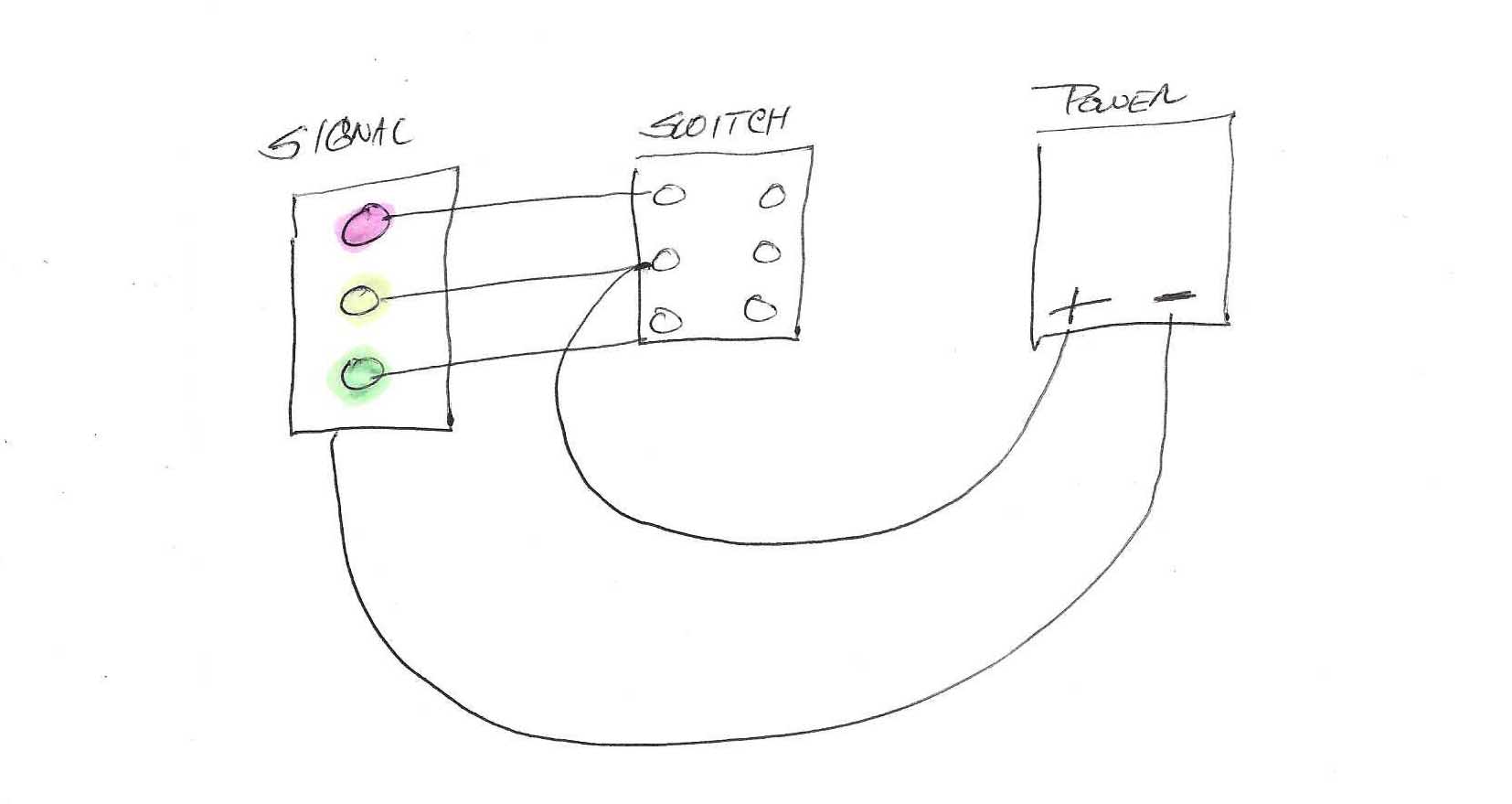
I feel stupid asking, since I have done this in the past, but my old age must be getting the best of me. I have tried to wire a 3 light block signal to a 3 way switch, as shown in the diagram, but only the red and green lights come on.
I can never get the yellow to work. I have fiddled with what I thought was every reasonable combination, but I only get 2 lights operating as I flip the switch.
Can any of your readers help me? I sure would appreciate a diagram.
David”
That’s all for this time folks.
Please do keep ’em coming.
And if today is the day you stop dreaming and start doing, the Beginner’s Guide is here.
Best
Al
PS Latest ebay cheat sheet is here.
PPS More HO scale train layouts here if that’s your thing.

very nice update thanks.
Hi David, not sure if this is the correct diagram as you have drawn it, because this will result in the Yellow being on all the time surely, as + wire goes to the wrong side of the switch. Have you got a three way switch not just a “on off on” ?
Difficult to tell from diagram
Mike S
David, I agree with Mike…your “three-way switch” is quite probably two-way with centre off. A quick check with a multimeter/circuit tester would confirm or deny this theory.
Cheers,
Steve
David, Use a small 1 pole 3 position rotary switch. If you can’t find a 1 pole, a 2 pole 3 position switch will work. Just use 1 pole.
I agree with Mike. The yellow should always be on or at least potentially on. I have run into this situation several times. LEDs have different resistances. If you connect a red LED and a green LED of the same type together at the same time, only the red one will illuminate. Since the switch is no doubt a two-way switch, in other words, your switch connects the center to the top pole or the center to the bottom pole. The yellow is always connected to power along with one of the other LEDs. Depending on their characteristics, the two other (R and G) LEDs prevent current from ever going to the yellow one. They offer an easier path for the current to follow. Adding some resistance to the R and G will solve the problem, but then the yellow will always be on with one of the others. You need a different switch. Rob
Brian
Always a thrill to see what you’re up to. I think you’ve improved the visual of your space and it looks great. It needs your final touches now to be spectacular. Throw lots of animals around that represent RSA.
David
you’re using an incorrect switch. You need a 3 way selector type with 1,2,3 on the face & wired appropriately. Your switch is a DPDT where the middle 2 are the common.
Big Al
Gracias Amigo
Yes David, I struggle with wiring also. Your “3-way” switch is functioning as being off in the middle position of your wiring representation OR the yellow light should be on in the middle position. I hope this helps.
Hello David, as a retired EE I have to inform you that EACH LED needs it own series resistor. Never EVER put LED’s in parallel because the LED with the lowest forward voltage will light up and not the others. Each color requires a different resistor value since the light output for each color is different with the same current. You have to experiment a bit to find the best resistor value for each color for about the same light output.
keep at it
Yes, Peter is correct. Google led resistor for all the info you need.
–
If you are ‘ married’ to the on-off-on switches, you could use as relay that is on
when in center position. This will mean that one led is on at all times
but given this application, I guess that would be ok.
Balancing the visual
brightness of the three colors can be a real pain — been there done that
and got the T shirt . I hope you have a nice collection of resistors.
eBay – get a couple hundred for a few bucks (US). Print out a chart of led resistor values that you like, so you have them handy. Also, there are several
on-line led resistor calculators – google led calculator and find one you like.
–
I’m a retired (80) IT support supervisor, and I use led’s all the time
in my many hobbies (home automation and robotics are main ones).
good luck –
not sure if it was sent or not
filled out the info required – will post again to be sure
ds