Lawrence has been in touch on wiring your layout.
Clambering around underneath a layout is an issue for some, so at first glance, this seems like a good way around it.
But it’s not. Sadly, it’s a great idea in principle, but not in practice, because of the fire risk.
So one to look out for. If you wondered why folk don’t do it this way, now you know.
“Hi Al
Thank you for all the work you do for us ‘Train Nuts’.
I have a hint for wiring the layout without ever going underneath the layout.
This works for people that build the layout and lay a sheet of plywood on the top of the framework. And then lay a one inch sheet of foam board insulation on top of that.
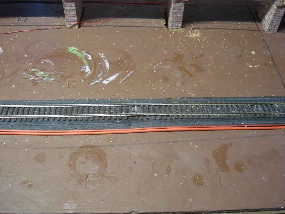
Initial Prep – I put down all my track first off and run the wires (16AWG stranded) on top of the foam board next to the track.
Feeder wires are 28 AWG. After that I run the trains for many hours over a weeks’ time, taking care of all and any problems.
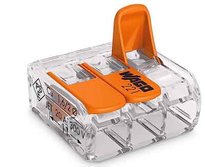
Once all the trains (engines + multiple types of rolling stock) run the complete layout with no more problems multiple times, it is time to hide the wiring. Also ordered something to connect wire junctions (every time I needed feeder wires connected) – Lever-Nuts
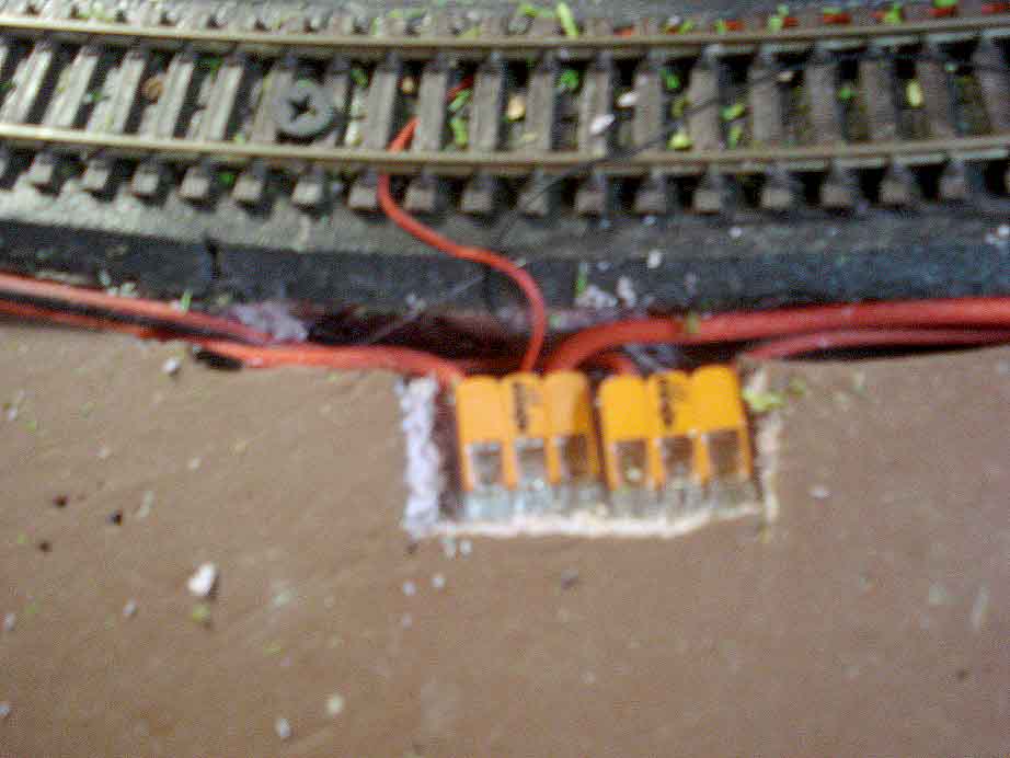
Start hiding – The second picture shows the wiring in place next to the track. Once the wiring is correct never mess with it. What is the saying ‘don’t fix something that works’.
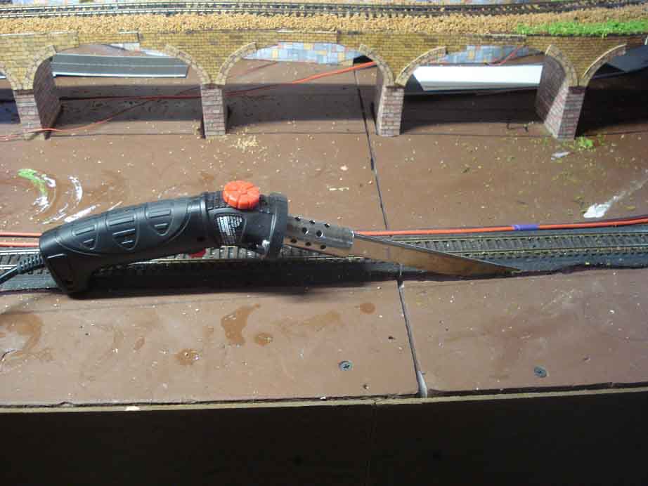
Followed by the Hot Foam Iron used to cut a trench next to the track. Wear a mask and glasses when doing this because it smokes, stinks, and not healthy. Well ventilated place also.
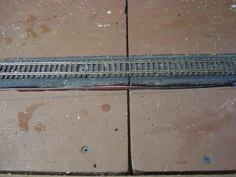
The next picture shows the wire placed into the trench. In some places multiple wires ended up in the same trench, for track and for lighting.
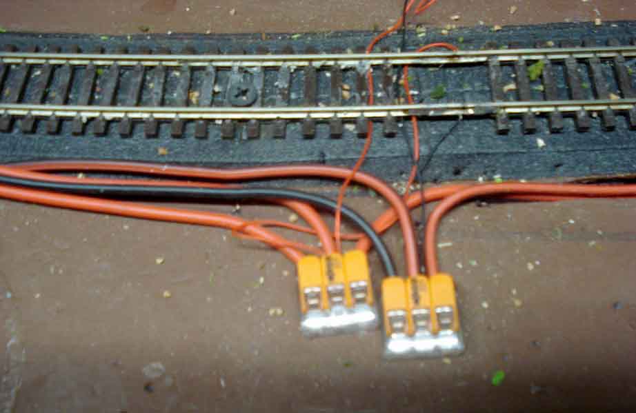
The next picture shows the Lever Nuts. One Nut for one side of the track. The other Nut is for the other side of the track. Using wire that is all red for one side of the track and one that is black or has a black stripe makes is easy to keep the wiring correct.
I have added two of the 16 AWG wire together and inserted in one section of the Lever-Nut when needed (the wire will fit but the insulation from the two wires will not).
To ensure good contact for the 28 AWG wire I cut the coating back three times as long and folded the wire in thirds (paper clip style) to give more contact points.
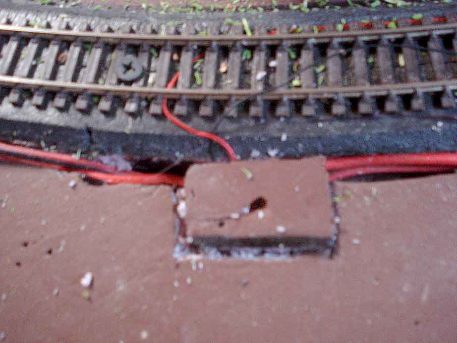
Putting the wire in a trench, the same needs to be accomplished for the Lever-Nuts. This is easy using a knife, just cut a square hole into the foam board. Next two pictures. Lower the Nuts into the hole. Take the top one eight of the foam square that was cut out and use it to cover the Nuts.
Finally ballast and ground cover as per normal.
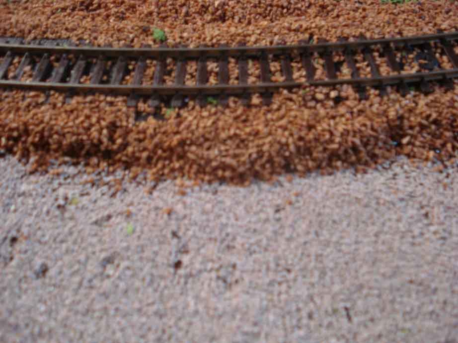
The ballast I use is ground walnut shell I get from Harbor Freight for $30. It filled 25 of the standard ballast containers I would pay $14 for each. Do this in sections to make sure you did not break any connections. My sections are anywhere from three feet to nine feet as is convenient for the layout. Run the trains after each section is done to ensure you did not create a problem.
I have done this without any problems. Remember I ran the trains many times before the final modifications. And I am running the trains again and again with no more problems – well except cleaning dirty track rails first time around on each section.
Elevated sections – Run the wiring in trenches next to the elevation structure. Run feeder wires up the structure as needed. Hide the feeder wires to the rear and tack in place with hot glue. Or cover the upright (over the wires) with brick work paper or concrete paper from Al’s download files.
Now in the process of adding scenery and never once climbed under or passed wires under the layout. I am using the same techniques for all the wiring for lights in the buildings. This wiring is accomplished after the buildings are given a home and before associated scenery is installed.
Save the pain and strain on the back and neck, And only work on the wiring at the same level you lay track. Enjoy.
Lawrence”
Have a look at the comments below and you’ll see all about the fire risk, which is why I say, it’s a good idea in principle, but not in practice.
One comment stood out for me – Bob’s. So I asked him:
“If someone was determined to wire above the table / bench, how do you recommend they do it safely?”
And here’s Bob’s reply:
“Hi Al – I don’t have an answer, other than to leave it exposed. There are many methods to protect surface mounted wires in the construction world but none would work for our layouts. I don’t often criticize others’ work, I’m a “your railroad, your rules” modeler.
But electrical and fire safety are important so I felt I should comment.
Thanks,
Bob”
I want to thank Bob for taking the time to reply, and to all the others that have commented on this.
And now on to Peter who is making good use of his retirement:
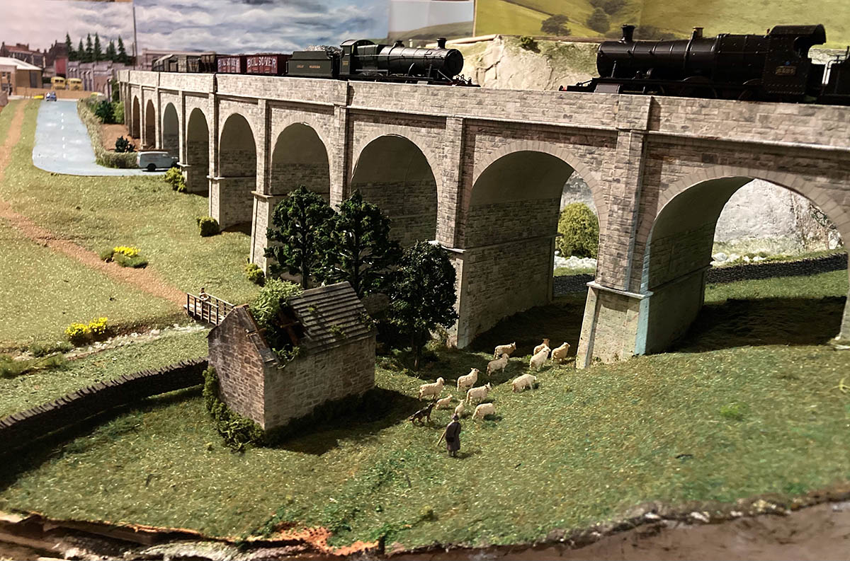
“I have been enjoying your posts for a while and decided it was time for me share my efforts with you.
I rekindled my interest in railways when I retired 5 years ago and having a reasonable space in the garage dug out all my old models from 50 years ago and bought some new track.
Needless to say I still have lots to do but here are a few photos.
Peter”
A big thanks to Peter and Lawrence.
That’s all for today folks.
Please do keep ’em coming. It’s jolly quiet this end.
And if today is the day you stop dreaming, start doing in join in the fun, the Beginner’s Guide is here.
Remember, it’s the start that stops most people. Don’t let that be you…
Best
Al
PS Latest ebay cheat sheet is here.


Don’t underestimate the ability of even low voltage wiring buried with scenery material or other (plaster) to overheat… can start a fire as well as 120-240 volt (England of coarse) buried in likely circumstances. Also downgrades the current carry capacities of wire sizing. Just as bad as taking apart 9VDC batteries and soldering leads on plates. A simple snap cap could of had same results with that tip.
This is nothing to take for granted or a great time saver when end results can be questioned. Was said John Allen’s Gorre & Dapheted was destroyed by a faulty electric heater catching on fire?? Maybe, maybe not. Also is a lawsuit possible in the works coming up with such ideas and posts?
Do exactly what you want to or think of, not my house. I even have bonded water and propane utility for any potential variations. Stories on cows entering barns and getting electrocuted some other time. You see I was master electrician at 24YO among other interests, started long time ago lol.
What a good idea.
Copper tape applied either side of the track and solder wire to the track. Use either multi strand or single works very effectively too
As always, great common sense ideas here and thanks as always Al for providing this platform for just that!
Since I am in the /USA what type of connectors do I look for and where would I find them for sale?
The comment from Rich makes a point, but may be somewhat strident. Properly fused and separated wiring is safe. I have noted that DCC power supplies can put out sufficient amperage to cause undersized wiring to overheat, so again, keep the proper wire size and fuse or circuit breaker. The voltage is less a problem than the amperage (overloading) need proof? Take a flashlight “c” battery, and a length of wire, the size we use for going from the power supply to the track, 16G or 18G. Simply cut a piece long enough to short the top of the battery to the bottom – do so over the sink where you can safely drop the experiment when the wire gets red hot! So yes, even 1.5 volts can cause a fire!
embedding wires can be dangerous and problematic as noted by others
A agree with Rich B. The buried wires could potentially overheat causing a fire. The fact that you have buried them in insulation which will trap heat, only makes this more likely.
Rigid foam board is HIGHLY FLAMMABLE and gives off toxic fumes when burned.
And how would you troubleshoot in the future? I like the Wago connectors but the would be better hanging under the layout.
I’m also a master electrician with over 40 years experience.
Bob
Lawrence
IMHO your connectors are very good but the idea of burying wiring in a layout base prevents safe modifications which for us never satisfied who need to change, add, upgrade or shift because we had another “Great” idea. For N or HO an 1 1/2″ hard foam base with a space above the plywood that you can fish wires, and wire Tortoise motors, works great without ” Going below”. This does not work with larger gauges.
Peter
What gauge? Very nice layout.
I also live in USA. TRY LOWE,S or HOME DEPOT In the electrical department. They have a good assortment of connectors. This is the time I miss Radio Shack. They also had an outstanding selection. You can also find a lot of ideas on Amazon. Being 73 crawling under my layout anymore is not my favorite pastime so I also avoid it where possible. I know everyone wants to use smaller gauge wire. That is fine. Just remember that the smaller the gauge the greater the resistance of the wire. If you have a long layout that becomes a real issue at the far end for current drop. And yes if you are using fine gauge wire it can get very hot. Heat we don’t want. Just saying that it is something to bear in mind while you are soldering, snap connecting and burying those wires. Last thing I want to read here is how someone lost their layout to a fire or god forbid worse. Stay safe people.
Foam and excess amperage spell possible trouble. Wiring beneath the layout for me..
I know wiring your layout is a pain. I’m still doing mine. I have an elevated section that is fairly substantial. I need bus wires for these areas but didn’t want it to be seen . I had heard about copper tape so I bought some and have used on one section so far and it improved my track voltage, no more stalling. I wouldn’t bury my bus wires no matter how well they worked. It’s low voltage, but it’s dc voltage and the current traveling thru them if not sized properly can overheat. If there was an issue, no access to the wire. Might have a short or whatever or you may want to change something or add something. My 2cents
For exposed wiring, I use plastic tubing and use it to simulate heavy conduits. Once some scenery is in the tubes become almost un-noticeable. Silver paint gives the look that is used here in North East Ohio.
Hi Al.
I’m with Paul (USA, 73, and crawling under benches are difficult) and have a question regarding his comment regarding long runs. Would it be safer running a larger gauge wire the length of the layout with branches periodically for feeding the tracks with a smaller gauge? Also would I need to run a separate long run for accessories (switches, lighting, etc.)?
Thanks Al for your webpage. Have learned a lot and know that I will never be the artist that so many of your contributors are.
Be safe.
A few comments.
1) wire size determines it’s amperage capacity, insulation type determines it’s voltage limit. If you use under size wire it will heat up, causing issues.
2) In DC wiring in particular, voltage drop is a concern. Use one of the online calculators for solar cell strings to get the minimum size wire for the maximum amperes expected at the maximum distance. Use one size larger.
3) Fuse protect the wire.
4) Invent a layout color code and stick to it.
I have setup power poles next to my track and use that to power my track
Lawrence: Fire is always a possibility anytime electricity is present. However, if one is careful, and does their “due diligence” with the wiring (as it appears you did), your idea seems like a great way to wire a layout.
The comments of Rick S. are “spot on” for eliminating any problems. Combining his tips with your practice of running the trains for an extended period of time before concealing the wires should do the trick! For anyone still concerned, I guess having one or two fire extinguishers handy would be comforting.
I’ve always thought about doing what Jack P. does. However, since I tend to use nothing smaller than #12awg for my DCC main bus, it would tend to resemble sewer pipes, instead of wires, up on the power poles.
I am a non electrical person. How does one determine which size wire and which type wire to use. My layout will be simple 5 x 10 but I want light up buildings and such and two main tracks. I like the on top method as I am 82 and do not crawl around . Maybe a road way or ditch or path next to track could cover wires? Thanks
I agree with the fire concerns. I have assembled lab washers and dryers and worked with primary coolant pumps and pressurizer heaters (think 480 volt heating elements). When I check my wire sizes I check current capacity and voltage drop before using any particular wire gage. It should also be noted that buried wire uses a different indualtion specification than normal to account for the local heating. Wire that is going to be buried in insulation has different temperature limits than wire in conduit or hanging in air. I strongly recommend going to one of the wire company sites and look for manuals or tables that what your wire needs to be capable of if you insulate it thermally.(like burying it in extruded styrofoam insulation (!!)). I would also be concerned about the flammability of the styrofoam at the maximum temperature the wire is capable of handling. I currently use tables from a Belden Wire manual that I downloaded from their web site several years ago. I use the table to figure out what gage the stray wires actually are electrically although it’s not always possible to figure out the insulation properties.
My layouts have been setup with block wiring using a common rail. I have always wired each section of the common rail as well as the isolated block rails to limit the voltage drop to the locomotives. Both go to a set of terminal blocks located where the block wiring power distribution switches are located. I started doing this with American Flyer AC powered layouts 60 years ago (without the common rail). I also don’t use smaller gage drop wires, preferring to have the entire run be generally either 18 or 16 gage wire. I have 14 gage wire but since my table is only 152 inches by 60 inches I don’t have any runs much longer than 7 feet (about 2 meters). I have used 20 gage for runs less than 2 feet but my wire hangs in air under the table for the most part and there is larger wire feeding the local box. I also check the resistance and voltage loss due to the wire before putting things together.
Because DCC feeds all the locos on the track the total currents are much higher than for block wiring (unless you have several locos running together). This increases the heating since you don’t know what the current is at any particular point in the distribution system. It underlines the importance of providing cooling for any enclosed wiring, possibly drilling cooling passages through the insulation to provide some airflow (or using one or two sizes larger to lower the heating due to current and possibly dropping single wires below the layout to provide additional cooling. Just some thoughts Ray
nice gives me something to think about
That’s pretty clever!!!
The ultimate method is what the Colorado Model RR Museum on Greely uses. This requires total pre-planning, which few do. Design your RR B4 you build the building. That way you can include a trench in the floor under where the layout will be built. They have several access and cross unders for staff to use and all the wiring is above or around you when you are down there. Of course it is hidden by the screen around the layout. They are closed Mondays to clean the track.
I’m lost on wiring to do’s don’t
My solution to the problem is to use overhead wires. They are on telephone poles so look realistic and lifelike. Electric utility sub-stations are used where wiring must interconnect. The wires are always easy to get to and the lines are not “fake”. They actually carry currant and perform a function.
My solution for wiring is I purchased q roll of Romex 14 AWG wire and I secure that under the layout around the entire loop. Then I strrip away only that needed to gain access or I use crimp connectors with push home tabs. These connections are short distance under the layout with short wire going right thru the 3/4″ plywood and up to the track. I cut the track with a thin 0.040″ grinder blade to allow for expansion. then I solder the wire to the track.
There is no way I would bury wires in foam.
Look online for all the commercially available wiring supplies. Not from hobby suppliers!
Make it easier to access the underside by building you layout on taller legs.
The lever type connectors have been available in the USA for many years. I used them in my business wiring displays. Available in many gages and # of connections from industrial supply companies.