Dean has been in touch with a post on his Atlas model train switches:
If you missed his last one, it’s here.
“In a previous post, I described by system for lighting buildings and hinted about my capacitive power supply, for snap switch control.
I’m using Atlas switches with their push-button controllers.
Looking back, I wish I had started out with the Tortoise switch machines, since they are more robust and electrical controls are simpler.
But at this point, I don’t want to deal with the hassle and work of converting all my switches.
A wiring diagram of my capacitive switch power supply is shown below.
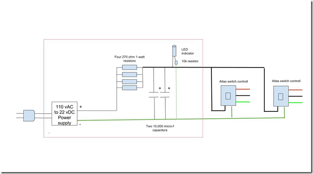
The power block on the left supplies 22 vDC from the house line. It’s from an old laptop I don’t use anymore.
The current flow in limited by four 270 ohm, 1-Watt, resistors wired in parallel to give the equivalent of a 68 ohm, 4-Watt, resistor.
These provide current into the two capacitors store the power to throw the switches. (Note that these are electrolytic capacitors that must be wired correctly as of polarity. If you reverse the connections, they might blow up, and would be totally destroyed.)
All these components can be obtained from suppliers (I got mine from Radio Shack which is pretty much gone).
The LED provides a power indicator. In operation the capacitors build up voltage to 22 v over a short couple of seconds.
When you push a button, the stored power quickly goes to the switch mechanism and the LED goes out.
When you release the button, the voltage again builds up and the LED lights.
Switch controls are connected to the red and green bus leads, one for each switch.
The red, black, and green leads go to a switch, wired as shown in the Atlas package the switches come in.
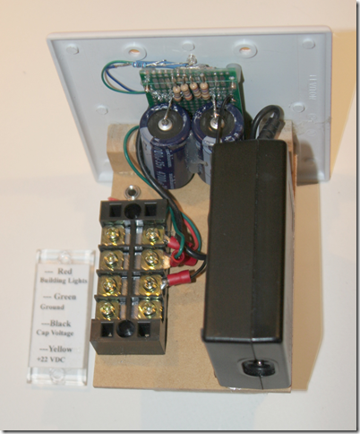
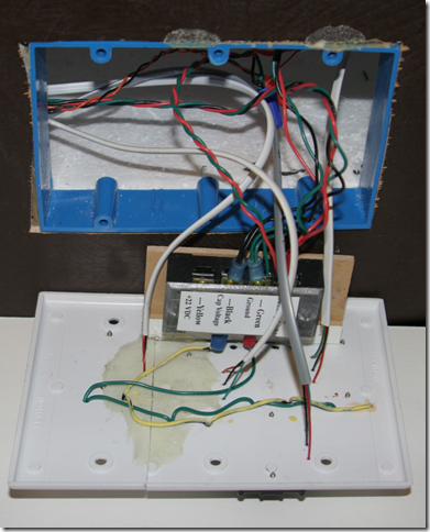
Everything inside the red box in the diagram above is shown below. The electronic parts are soldered onto a printed circuit board with many unconnected holes (from EBAY). Wires are routed and soldered between the components as needed.
The circuit board is held to the front plate with screws and spacers. Everything else is held together on a wooden board with hot glue which is then hot glued to the plate.
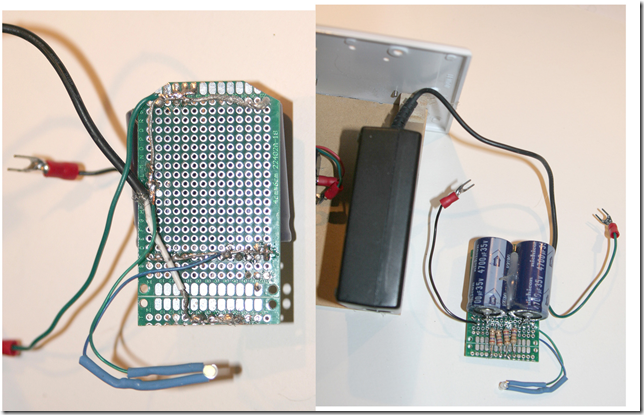
The front and back of the circuit board is shown below. Wiring is not critical, just make sure everything is connected correctly. The resistor for the LED is inside the blue shrink tubing.
Below are the two control panels for the yard at Cassiusville (panel on the right) and the Inverashur passing siding (panel on the left, Inverashur siding behind the town).
Another switch on the right of the Cassiusville passing siding is out of the picture. Readers of my last blog will recognize the station and mine.
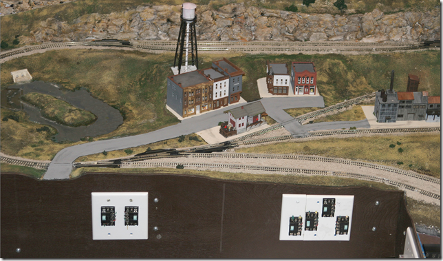
The back of the yard panel is shown below. They don’t make 3-gang cover plates, so I have to cut a 1-gang and a 2-gang and glue then together with epoxy.
I hope I have made everything clear. Write in your questions.
Dean”
A huge thanks to Dean for sharing he’s learnt on his Atlas model train switches- please do post you comments and questions below.
And don’t forget today is the last day to save $18 with this offer on the latest print out scenery. Here’s what it looks like:
That’s all this time folks.
Please do keep ’em coming.
And if you want to jump in and start your layout the Beginner’s Guide is here.
Best
Al
PS Latest ebay cheat sheet is here.


Hi Dean
Great info Dean but to save you time and a lot of messing around, cover plates are available in 1,2,3,4,5 and 6 configurations. I am presuming you are in the US. I am in Canada and these plates are readily available at most electrical outlet stores. I presume they supply more but I have only installed up to six. I hope this helps.
Good advice – should help with lighting which is key to an awesome display. Most important for those fathers and grandfathers is the time spent with children building a display. They can learn so much!
Bob
The last time I had a train layout was back in the 1950’s. I still have the American Flyer trains and Plasticville buildings. All were presented to me once again, by my children in a beautiful handmade box crafted by the oldest son. Now 75, I
still have that box, but never have had a desire to rebuild a layout. However, I
do look forward to the daily report by Alastair Lee each morning and is usually the first email looked at. Having a little haven which shelters us from the travails of
the world’s happenings, is indeed a blessing. Thanks, Alastair.
Adolph – Marengo, IL
Two good sources of electronic parts (WEB orders Only) are DigiKey.com and Mouser.com. They are distributors of a wide variety of electronic parts, tools, prototyping stuff and some chemicals.
What are the Atlas switches? Mine are not momentary contact or buttons. They are slide switches. If they are momentary contact, can one circuit be used for many switches?
So informative, Dean … even us old codgers can learn a trick or two. Thank you for sharing your knowledge and experience with everyone.
Tom (USA).
I am kinda lost here.
I have a small layout, in DC with 24 different tracks and 17 switches. They are Atlas with the push- button controls wired to the AC side of a 30 year old controller, I have two controllers on the lay out, ( two different Locos at the same time ) but only use power for switches from one. It works fine. When I wired it I made all the push-button controls so when switch button is to the right the train goes straight thru the switch, when button is on the left the train will go to the next track and that depends on the direction the train is moving, Makes you think.
NV Bob
Adolph, I also have some original American Flyer trains from the 50’s, but I am finally working on a layout (I am 65). My daughter is moving to Rolling Meadows next month; too bad you don’t have a layout to visit, but I also enjoy seeing the others’ work in this forum. Thank you Alastair! Great wiring Dean! I am using the tips I find here. Mike
I agree with Bob. You don`t need all these components, Atlas switches connected to the ac terminals get power from controller I connected to one and then connected 6 more with spade terminals 0n switches switch part no #56. They are slide switches momentary contact, cheap and very easy to use. Buy the book Atlas #12 complete wiring book. for all scales and many track configes. Makes it easy. don`t need all that high electrical parts. Enjoy don`t complicate the Hobby. Tom
Tom, true you can go with the straight Atlas controllers. But if you want a more prototypical fluid slow motion switch movement, then you need to add a circuit like Dean’s or convert to the Tortoise or similar type switch motor. Tim
Some of you missed his point. He was trying to simulate the Tortoise slow motion switch. Not the “snap” of the Atlas Snap switch.
Well I guess I missed the point of the slow motion as I have never used tortoise type units. I do think they may be more real life like than the Atlas, however not all of us can afford those types of unites, let along understand the wiring Dean did, that wiring is way above my pay grade.
NV Bob
has anyone tried to use electromagnets for switch controls?
I really can’t imagine why one would even care about the speed at which a switch moves the track. If it works fine why mess with it? To me this is just creating a problem where none exists!
F.Y.I.:
• All layouts using 110-120 V.A.C. devices should be plugged into a GFI Outlet.
• And one should invest in Surge Protection, either an outlet plug-in device or a surge strip.
The frequency of line surges has more than doubled in the last few years.
One can Google GFI or surge devices to get more information.
Gene; switch machines are nothing more than an electromagnet with a moveable, although, there are two coils, one for each direction of movement.
That’s supposed to be moveable core. That’ll teach me to read before sending.
I use a little store bought circuit board called the Snapper. It’s a capacitor discharge power controller specifically designed for twin-coil switch motors. I use a 24v AC wall wart supply used for irrigation controllers to juice it, because I found I needed more punch behind the pulse when throwing over multiple switches and the Snap Relays I use for signalling.
Wiring by any measure the most difficult part of our hobby. On a previous layout when I had younger eyes I had cars with headlights, there were streetlights and of course interiors lighting on buildings.
Now my latest layout is strictly day time operation. But good to see all the innovation and tips here as always.