Dean’s been in touch with a great explanation on model railroad lighting:
“Greetings from Dean, across the pond.
Lately, there has been a lot of discussion on this Blog about LED lighting, and in this post, I talk about LEDs and how I use them for lighting building on my N scale layout.
An LED is a special electronic component that emits light when current is passed in the correct direction. If you apply a small DC voltage to an LED (positive voltage to the positive lead, negative to the negative) then begin to raise the voltage, nothing will happen until you reach the working voltage of the diode. Then it will begin to conduct and emit light.
But, unless you limit the current through the diode, it will quickly heat up and destroy itself since it is virtually a short circuit. For many LEDs, the working voltage is around 3 volts and the maximum current allowed is around 20 mA (0.020 amps). When you buy them, these characteristics, working voltage and maximum current, will be specified by the seller.
Below is a photo of some LEDs I have used. The positive lead is always the longest of the two. A resistor is also shown. Typical sizes are 3 mm and 5 mm and I buy these in bulk packs of 100 from EBAY for $4-$5, postage included. Thus, they run around 5 cents each. Resistors in bulk packs of 100 are about 4 cents apiece. Also shown is a box of the two sizes in 5 colors that I got for around $5, postage included.
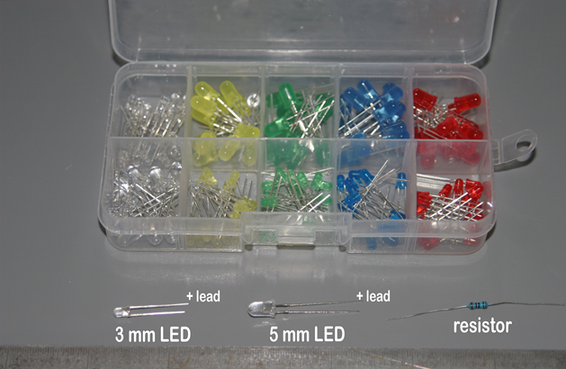
You can also buy 1 mm LEDs usually with an included resistor and leads which are meant for model railroad hobbyists. I’ve seen these at $7.50 plus $2.50 shipping online. Or $10 each compared to what I pay for an LED and a resistor, $0.09. That’s why I wire my own! Lots of businesses sell bulk packs of electronic components for next to nothing on EBAY. Often these are shipped from sites in the US in a few days, although for some you have to wait for shipping from China.
Below is a simple circuit to show how an LED is wired. A battery, a 1000 ohm resistor and an LED. I just placed them together without solder to illustrate the circuit.
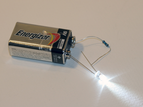
The value of the resistor can be calculated with the formula
R = (supply voltage – LED voltage) / the current
I use a supply voltage of up to 9 volts and most of my white LEDs are listed at voltage = 3, maximum current = 0.020 amps.
Then the resistance is
R = (9 – 3) / 0.020 = 6 / 0.020 = 300 ohms. This will give the maximum amount of light, but I prefer to run these at a lower current for longer life, and I increase the resistance to 500-1000 ohms.
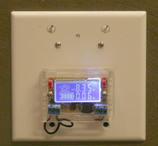
To change the voltage to the LEDs, I bought a variable voltage supply (again from EBAY) that is shown below. I use a 9-volt “wall-wart” from an old piece of electronics to supply the voltage to this variable supply. (See the circuit diagram further below.)
The voltage supply costs around $5, came with a Lucite box, and indicates both voltage and current. Make sure you connect the correct polarity to the variable supply from the wall-wart or you may destroy it. There is usually a diagram on the wall-wart that indicates which is the positive lead.
I use a regular blank electrical box covers (above) extensively on my model railroad lighting. To hold the covers, I saw a blue plastic electrical box down to a height of an inch or so and glue it into a square hole cut in the fascia panel of the layout (below):
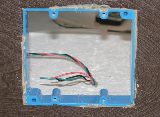
Three wires, which I twist together by chucking them in a drill, run between each of the boxes on the fascia. The colors are:
green is ground; red is to the LED lights, +0-9 v DC; black is +22 v DC for switches (I’ll describe my capacitive discharge circuit in a later post).
The wires terminate in junction blocks shown below (note the forth connector labeled yellow is for future expansion). The junction block has a plastic cover and I attach a printed label to this.
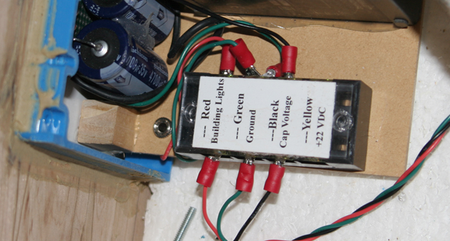
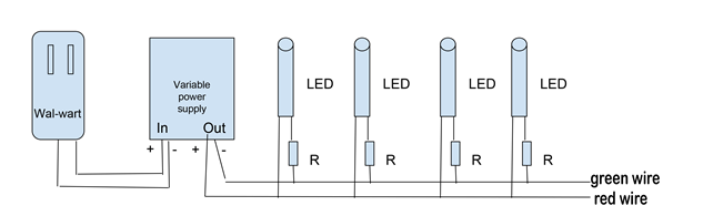
Here is a sketch of how the wiring goes together. Note that I can connect any number of LEDs and associated resistors to the red and green wires. Normally, I use from two to four LED/resistor pairs for each building.
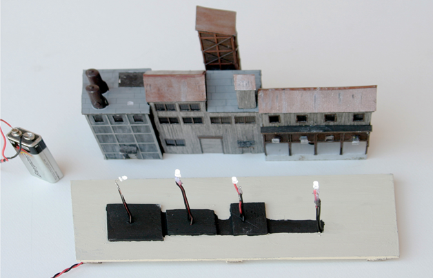
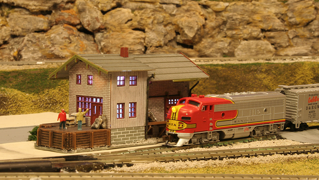
Below are two lighting examples, a mine (built from an N Scale Architect kit), and a New Model Power freight station kit. The mine is basically four boxes, put together.
Inside each box is an LED/resistor built up like a stick. The two wires are insulated with shrink tubing and the height is adjusted so that the LED sits at the top of the box.
The light is then bounced around the building. The freight station has two LED/resistors.
The base for the mine holds the four sticks and interconnections are made in slots below the base. In this photo I used a 9-volt battery to light them as a final test.
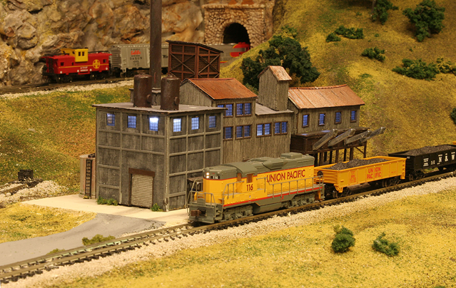
The mine lit up in all its glory with this simple model railroad lighting! The kit is a model of the Eagle River mine south of Minturn, Colorado. I first saw it in 1974 and the buildings are still there. It operated for about 100 years until 1984 and is a pollution source.
The lighted station.
The layout is lit by two banks of fluorescent lights and five 110-v LED flood lamps whose intensity can be varied. When I operate the layout, or photograph parts of it, I first vary the overhead lights and exposure to give what I want (daylight, dusk, night) then adjust the LED power supply to give the right effect. I place a camera on a tripod, since exposures are often a few seconds.
Dean”
A huge thank you to Dean for taking the time to go through his model railroad lighting – I know it’s is always a topic of conversation on this blog.
And who can forget Fred’s model railroad lighting? It has to be seen to be believed:
Model railroad building lighting.
I’m still getting the odd email on the roads and pavements bundle.
And I thought one or two of you may feel like barricading the doors and keeping yourself to yourself for a week or two.
So keeping busy on with some of the print out scenery may help pass the time. Here it is:
And lastly, a few of you have have asked for the roads and pavements link again.
We’ll, I’ll go one better than that, here’s the sale offer too:
The latest prints consist of 4 roads, 4 pavements and 4 tarmac tracks – giving you a limitless combination for your layout. In fact, it’s only limited by your imagination.
John kindly put the below together just to give you an idea of what you can come up with. Here it is:
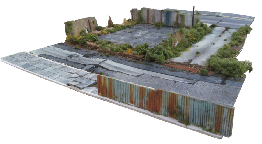
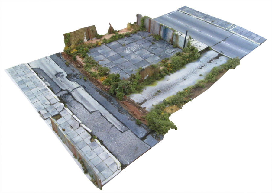
Just like every building in the store, it’s all made from print outs. Here’s his video. Hope it makes you smile as much as I did.
Latest ebay cheat sheet is here.
The prints for the roads and pavements that John was using are in the store already – but if you want them use this link to get this silly low price.
Also, until Sunday night, I’m bundling this fantastic green house with the roads and pavements, for free:
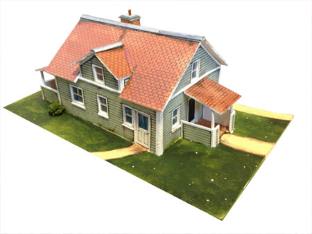
So if you’d like this fantastic house, as well as the roads and pavements, all for just $9.97 please click here to buy, or the button below.
(The house sells for $9.97 on its own, so it’s a great saving).
But remember – only until Sunday night.
Everytime I watch one of John’s videos it always makes me want to build something. I love his enthusiasm.
He also does a great job with all the scenery store it is all made from print out scenery (you just download it, print it out and stick it together).
That’s all this time folks. I never know what’s going to be in my inbox each morning – model railroad lighting tips, printable buildings and scenery, or whatever… I don’t think I’ll ever tire of it.
Please do keep ’em coming.
And lots more like this in the Beginner’s Guide, if you want to get going on your layout.
That’s all this time folks.
Best
Al
PS Latest ebay cheat sheet is here (still updated everyday).


Thank you so much for the LED lesson. I will be adding lighting to my layout soon and your explanation and information is what I was in need of. Cheers! NJ Mark
Excellent explanation of your supply and bus system. Good to see a protocol in place!
One further point; most buildings (unlike the mines) are not one room, and so benefit from internal walls to make some windows lighter/darker.
And if you’re modelling modern era, you may need flashing colours for the TV, which may be more than one per house!🙂 These LEDs can also be bought from eBay for pennies, but they are a bit more than Dean’s, even in bulk.
Also watch out for the colour of white. Modern can use the blue-white cool, but most places require tungsten warm-white
Your remarks are valid, but I should have made it clear. I do buy LEDs, resistors, and the power supply on ebay.
And I would now use “warm white”-I didn’t see them when I bought these “water white” ones.
An advantage of my system is that you decrease the lighting of an individual LED by increasing its resistance, thus, ending up with different lighting.
Excellently constructed article. Very clear for us novices. Thank you very much. Now please give a lesson in wiring up a switch!
I love this website. Thanks to the author of this site. Lots of great ideas to use and the contributors are good people to share their ideas with the rest of us.
I like the article, thank you for posting it.
Good work mate! Having the calculations for the resistors is gold!
Excellent much usefulness for me
Hello Dean,
EXcellent demonstration of LED lights for N scale layout. IN fact I am also perusing with N scale, ROCO. This text of yours is of imminence help which now I can adopt. Thank you so much for much needed help.
Regards,
GOPAL DAGA
KOLKATA/ INDIA
Thanks for the info. That will greatly help me light my buildings. I tried another
way which didn’t work out.
I have been an electrician for 41 years & I tip my hat to you. You have explained doing it well & professionally & I don’t think I could have done as good a job as you did. Great job!
Excellent write-up Dean, many thanks.
The variable voltage/current supply looks really useful, you say it came from e-bay is it easy to find & inexpensive?
Modern electronics has come a long way, such modules used to be relatively expensive for hobbyists, I can see many uses for such a small device.
Once again a very well written article.
Bernard
what is a wall-wart? please explain and where to buy them, Is that there real name? Thanks, great pics Tom
Great Article, great explanation of LED tech. While you use them in N, I operate in O. The electronics are the same, and one terrific advantage is that over a lifetime of use insuide a building, you’ll most probably never have to replace them.Thank you
Great article, very informative !
I’m interested in your variable voltage/current supply from e-bay.
Can you tell me the supplier or how to acquire one just like the one you used ?
Thanks
John
What a wonderful article! VERY helpful and I appreciate all the information as I too am about to work on lighting design on my HO layout. Insightful, well written and very easy to understand for folks like me that enjoy this kind of help. I have never commented on an article before, although I have enjoyed MANY of them, but this article in particular I found to be incredibly helpful! THANK YOU again!!
How can I possibly add to the comments so far. Obviously a well though-out and planned article. That is Greatly appreciated.
Here are some answers to a couple of questions:
A “wall-wart” is a term used in hobby electronic articles that I should have explained. It’s a box that plugs into a 110-v (in the states) power socket on your wall. It has a cable that terminates in a plug that goes into some electronics, a laptop, a router, an electric shaver, a battery charger, or whatever. They come rated for voltage and current. I’ve got a drawer full of them that I have salvaged from old stuff. The wall-wart also indicates which of the leads is plus and minus. Usually, I find a socket that fits them and put that into my circuits. An advantage of these is that they have current protection circuits and don’t need fuses.
For a variable power supply search on ebay for
DC-DC Adjustable Step Down Power Supply Module/Voltage Current LCD Display Shell
You’ll find lots of sellers. Find one with a low price that preferably is in your country who can mail it to you quickly. Otherwise it might take a month since it comes over on a slow boat from China (literally). Best price I’ve seen is less than four bucks.
Thanks for all the great comments, Dean
I also have never heard of a “wall-wart”. Is this some mane used in Europe that us from the states may know it as something else?
the term ‘wall wart’ is a relatively new slang for the modular power supplies that most devices are powered by. Typically they come with land line phones, or old answering machines. These modules are usually black and plug into the wall, they have a small cord that powers some device. They got the name ‘wall wart’ since they look like a wart on a wall. they are usually about 2″ x 2″ x 2″. On their bottom it will list the voltage and current capability, so you will have to use above equation to determine your resistor, also each LED will draw current, so you will have to add up all the LED’s on your string, this total current should be less than the rating on the wart. Be careful some older warts my be AC output as opposed to most newer ones which are DC, you want DC. You probably have them in your junk drawer already but they can be purchased at a number of sources, you may want to try your local Radio Shack.
A wall-wart is the transformer circuit that plugs into your wall outlet and converts the 120 volt AC to a specific DC voltage. They can be picked up for cheap at many thrift stores. The simplest variable power supply is just a rheostat (variable resistor) with some type of voltage meter wired across the out put terminals.
Very informative article, thanks for sharing.
thank you for your article, very informative and an area I can use more knowledge in. Peter
An idea to create a warm-white glow from a cool-white, (clear) LED.
take a thin sheet of parchment paper and roll it into a single layer tube or straw shape that slips over the white LED. Remenber to use a propr valued resistor to limit the LED’s current and brightness.
For creating the flicker of a TV or a campfire, try usng a LED from those flickering electric candles that are popular around Halloween time.
a great how to. lighting is very popular in this hobby so this is great to copy thanks for sharing.
Excellent article; brilliantly explained. So I now know exactly what I have to do whereas before, I was just a little bit nervous to try.
I also liked the explanation of the Wall-wart as I was again, a bit confused until it was made clear.
Thank you Dean.
Mike (Andover, UK)
of all the comments i have read, i don’t put led’s in myself. i bought a 18 ft. strip of led’s w/ transformer and cord to plug into ele. outlet. i bought it in cal. put it under the second level and it works great it even dose different colors, slow, fast, its great.
Dean mentioned other posts, is a copy of these listed anywhere?
Hi Al
Many sincere thanks for your wonderful website which is such an inspiration together with your printable sheets.
Just a thought, I wonder if it’s possible to include some British profile buildings as well, especially modern outlines for the U.K. Modellers. It might be a useful extension for your business.
All good wishes,
David
Dean
Thank you for taking the time to explain the way you do this. I have had many explain this before but, you did it so even I got it.
Are colored LED’s also 3 volt? Is there a minimum voltage to activate LED’s? a great article.
Super. I’m bookmarking this on my computer.
I can only echo all the comments regarding Dean’s excellent article.
I also what to acknowledge John’s terrific workshops with paper printed buildings, roads etc. John is an absolute natural. He is entertaining, informative, illustrates so well, he by far is among the best of the best with workshops of this nature.
Such top notch material today.
Thank you Dean, John, and al.
Dick from Hardin Mt USA
Fantastic how to course on LED lighting.
Just a suggestion, for L E D lighting I have used power supply from old Desk Top computers, there are several D C voltages (resistors required) its a good heavy duty power supply and would take many L E Ds to overload it, I have not blown anything up yet except a few L E Ds
John was very educational AND entertaining. Great work, albeit tedious (until one develops the technique, I’d suppose).
Good article. You should note that there are LEDs with two colors and only two leads. Forward gives Green, and reverse gives Red. Connect in series with stall motor switch machines on 12 volt circuits without resistors, shows both switch motion and end of motion. The colors show swtich position and it is possible to have up to 3 LEDs in series with one switch motor. Silicon Diodes have a voltage drop of 0.7 Vdc while LEDs tend to have 1.4 to 1.9 Vdc. LEDs come in 2 standard sizes, T1 at 0.12″ dia and T1.3/4 at 0.2″ diameter. The voltage drop is a Log curve based on current. The number of LEDs in Cars and devices is enormous today.
Echoing all the previous comments, a well presented tip. I plan to use this lot in my “G” outdoor layout lighting.