Bob’s been in touch with his Hand layed HO scale turnouts.
Have a look at the ‘bridge’ he made so he could lean on his layout and put in the new turnouts. Clever stuff!
“Alastair,
As you know layouts are always evolving and in that evolution challenges present themselves.
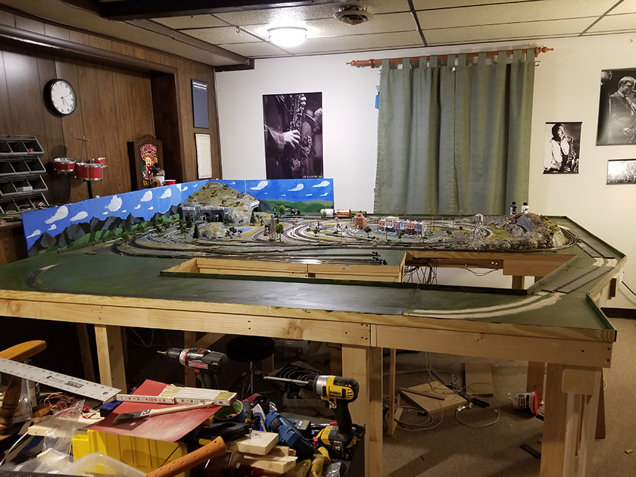
My original 4×6 HO layout expanded to 5×9 which was all that could be done in a 9×11 room. So I moved everything to a larger room and expanded it again to about 9×10 (the first picture).
I got everything the way I wanted with a roundhouse, turntable, and larger station. The problem was all the turnouts. They are all Atlas and there is know positive way to know which way it is turned without physically looking at the switches.
I saw a video on how to use red and green LEDs on a control panel to indicate the status of a turnout. To do that kind of thing with Atlas would require using Atlas relays. Looking at the expense I decided to try using a Tortoise switch motor to operate an Atlas turnout and have LEDs on the control panel and it worked.
So I took the plunged and decided to convert to all Tortoise motors for my turnouts and redo my control panel using DPDT toggle switches.
The first challenge was to add the Tortoise to the existing turnouts. It required drilling from under the layout to access the operating arm. It was tricky getting the operating rod fed into the slide bar but once in the Tortoise worked fine and I got my indicator LEDs working.
The next Challenge came when I used one DPDT switch to operate both Tortoise motors for a crossover. Because the motors were both working at the same time in parallel, there was too much voltage for the LEDs. I burnt two sets before I decided to search online about using Tortoise motors and LEDs for crossovers. I needed to add a resistor. Now the crossover LEDs are working.
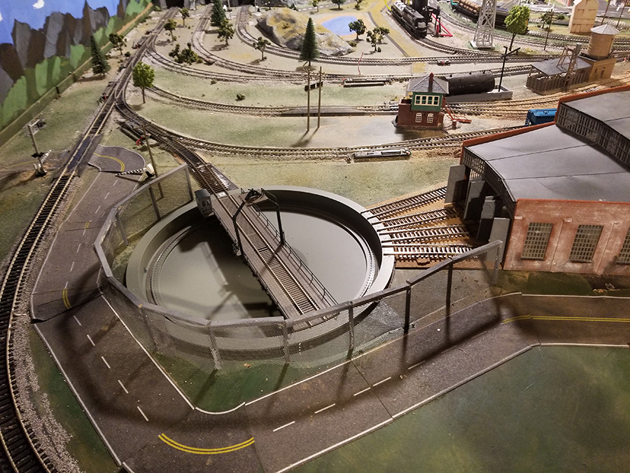
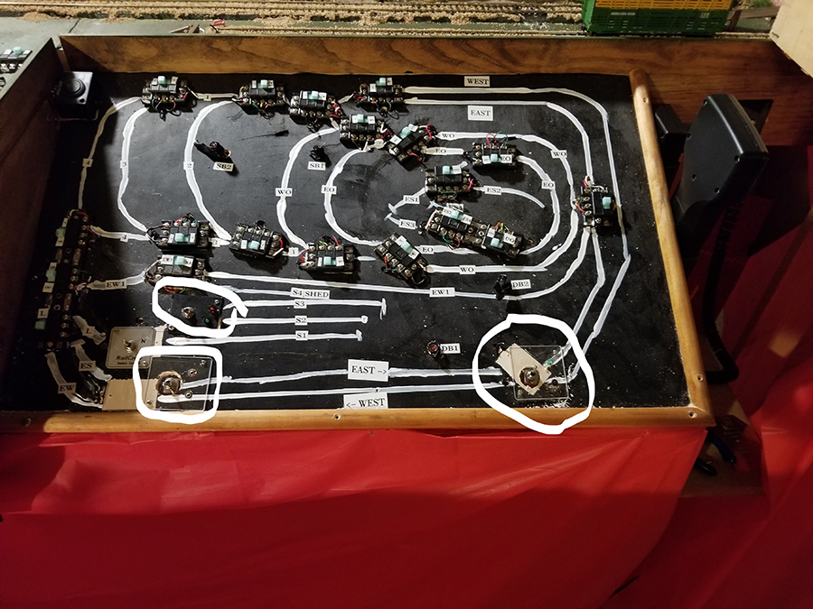
The third challenge was to get to three turnouts to cut off the excess operating rod ( picture 2). The three turnouts are on the left of the picture. The turnout closest to the turntable I can reach.
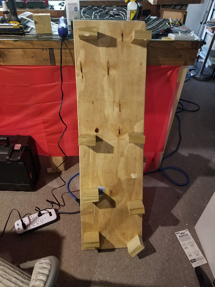
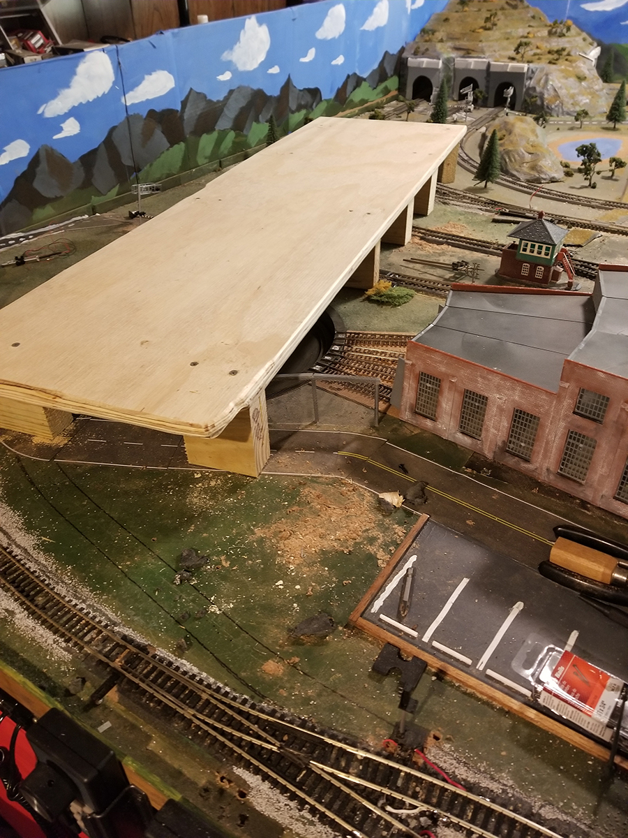
To gain access to the turnouts I decided to create a bridge. Because of the fence around the turntable, the trackwork, and trees, I couldn’t just lay a board across. So I got a 2’x4’ 3/4in piece of plywood, cut it to 14in by 48in, and cut eight blocks out of a 2×4 about 3in long and placed them on the layout between the trackwork.
I took the bridge out of the turntable and I put yellow wood glue on top of the blocks and set the plywood on the blocks and screwed the plywood to the blocks. The second picture shows the underside of the bridge.
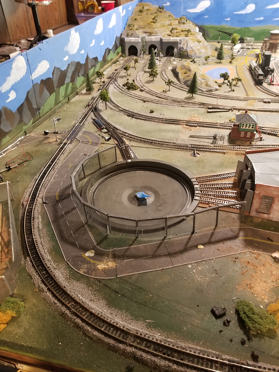
The picture shows the plywood bridge in place ready to use. The layout is sturdy to begin with and the plywood bridge distributes the load to eight points. When I get all of the turnout motors replace and have my new control panel I will send an update. Maybe even post a video.
The picture shows my current control panel. The three circles highlight the DPDT switches I use to control two turnouts and on crossover.
Installing the DPDT switches required me to use plexiglass squares to mount the DPDT switches because the existing panel is 1/4in plywood. It also required some tricky work under the panel. Then I realized that I didn’t want to replace the existing Atlas slide switches one by one using pieces of plexiglass.
I decided that I would build a whole new panel and put it in place when I was ready. I bought a 2’x4’ piece of 3/16 Masonite, usually you see it with a bunch of holes that you can use to hang things. I also wanted to keep the work under the payout to a minimum.
I took a piece of scrap particle board and cut a 3/16 groove in it and stood my 14in x 24in panel board in the groove and screwed two pieces of scrap alongside of the panel to keep it upright.
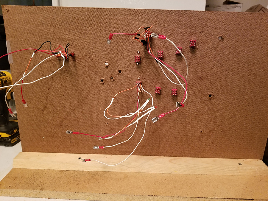
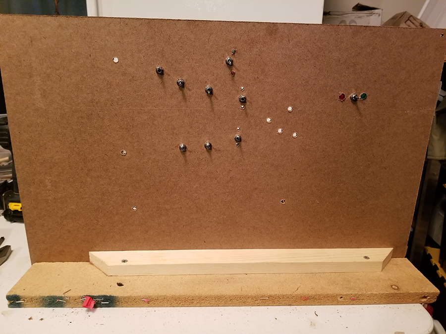
Now I can work on the control panel sitting at a work table. I am using quick connects on the wiring so when I put the new panel in place I can ad quick connects to the existing wiring and plug everything together.
Bob, Virginia.”
A huge thanks to Bob for sharing his hand layed HO scale turnouts. Some very clever stuff going on there.
If you want to catch up on Bob’s pevious post, it’s here.
That’s all for today folks.
Please do keep ’em coming.
And if today is the day you get started on your layout, the Beginner’s Guide is here.
Best
Al
PS More HO scale train layouts here if that’s your thing.
Need buildings for your layout? Have a look at the Silly Discount bundle.

I have converted an Atlas point to use a Peco sidemount point motor, another Atlas point uses an old Hornby point motor, and a Bachmann EZ track point also to a Peco sidemount point motor. I used what I had in the scrap box!
My control is DCC using Hornby Railmaster so the mimic plan on the computer screen shows the direction that the points are set to.
Geoff Tate, Corbridge, Northumberland and The Villages, Florida.
Your bridge is a great idea and the layout is super! Cheers! NJ Mark
I would like to see more of how the featured layouts run rather than solving electrical issues. The pictures sometimes are fragmented and give no real presentation of what the owner is/was trying to achieve by the overall design. Anyone can lay down track, but to build a layout, I.e switching, point to point, heavy industry, logging, mining etc, is something totally different.
I am Bob not Bill, but I really don’t care what you call me just so you don’t call me late for meals. Appreciate the comments. Not everyone is a ” Dangerous Dave” or scenery builder like John and so many others who contribute here. I don’t have a specific plan on what I want my layout to be; hence the sparse scenery on the expanded portions of my “platform,” I view it as a blank canvas that I am experimenting with how I want to run trains. I post things I hope will help others. I am not preparing to publish in Model Railroading. My only goal i to enjoy running trains.
Great idea for accessing those larger layouts or ones built up to the wall. I guess having the substructure strong enough to take the weight at each support is the secret.
To Bob, my intention was not to denigrate or criticize, just an opinion from another modeler and railroad enthusiast. The question still lingers, how do you run your trains? That’s what I want to know. Imagination and pretending are part of the hobby.
I love your idea of a kneeling bridge. I need one.
Rob McCrain – Farland Howe
I for one like your article. I am planning a layout to be built soon. I do not want anything complex and as my stuff is decades old have no intention of DCC. So to see something that is not super complex is encouraging. My plan is to run 3 or 4 lines using separate transformer controls. Something akin to Dangerous Dave….lots of scenery and trains looping around a large layout
I built the platform with 1×3/1×4 l-legs with bracing. The top is 3/4in MDF and some sections are 3/=in plywood..
I run 5 locomotives. Waiting on a BLI ATSF Mikado with smoke due out early 2020.. I have a NCE Power Cab and 3 Pro Cab 06 controller. I have a SB 5 and a DB 5 each connected to two PSX 1 circuit breakers giving me four separate blocks. I have a siding tha is not connected to the rest of track age tha I use as my programming track using the Power Cab.
will some one plz answer ? how much power transformer do I need to run 9 Ho locos heavy pulling , 30, 40 cars each ? I am planning my layout some help would be appreciated ! it will be around 15 foot by 12 foot !
I just saw the part on switches, interesting. I have Kato track and switches and have found a product that will allow me to use leds and switch together. They are touch toggles and you put them under glass. They work well and the track plan I painted on the glass with some pics that I have found for my railroad. The friends that come over can instantly see where the switch and which way it is going. This way is not for everybody but for me it is fine, I have it under my layout and pull it out when Needed. It moves the switches well and also lets me know by the color of the leds which way the switch is moved. Keep up the good work. there are so many ways to do things.
I use a 2mm magnet glued to the point throw rod and hall transistors,connected to an IC chip to drive bicolor a LED. Georg
Love the pics and the layout. It makes you happy that is the important thing. I’m in the hobby to enjoy myself no one else. I want to play with my choo choos not cameras etc. Although I have taken absolutely horrid pictures thats okay.
An other solution to controlling ATLAS switch machines is to use the 751D turnout controller available from Ken Stapleton Electronics. It is inexpensive, very easy to mount on control panel,& gives a good snappy output to the switch machine motor,as well as powering 2 LEDs to indicate turnout position. I have 20 of these operating on my layout, & am very impressed with them.
What happened to the old school way of doing this? You use a passing contact toggle switch in your track diagram so it throws across the line of the track. The switch throws left or right (up or down) which is the way the point goes, so looking at the switch tells you which way the point is. No extra cost or wiring just simple, works every time unless you get wires round wrong way but that is easily solved.
Bob; I thought your comment about quick disconnects on your switch wiring was interesting. Might I suggest you use DB25 connectors, and run your wires to it/them. Attachment to the connectors is by screws, not soldering, and they are plainly numbered.
This would mean you need to make or break only one or two connections, not a whole bunch.
Dave H of Clyde – I Googled DB25 connectors but couldn’t find anything useful. Can you post a link? Thanks
There are such a variety of interests and opportunities in this hobby. Great examples here.
really nice info. i might try it.
Isn’t all track hand laid? As opposed to laying track with feet?
Bob , excellent layout , shows true scale and realistic scenes , very nicely indeed , good work man .