Brian’s been in touch with a nifty little model car light kit:
“Hi Alastair,
been keeping myself busy with small projects because both levels of my current 14ft by 10ft shelf layout have been sold and the projects below will be for my new layout when it gets built.
In the meantime I have been putting LED lights into some of my HO scale resin cast vehicles, compliments of Temu. (China)
I ordered some very small LEDs from them and started putting them in as headlights.
They are powered by a ‘buck’ module. The ones that I use can be adjusted down from 12 volts input voltage. I set the output at 2.7 volts to give me the correct brightness .
A buck module (shown below) is a step down converter for DC. I think I paid about ZAR13.00 each on ordering 5 at a time.
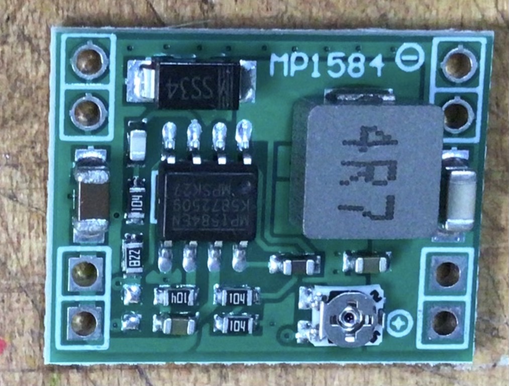
The small silver screw at bottom right is where you adjust the voltage.
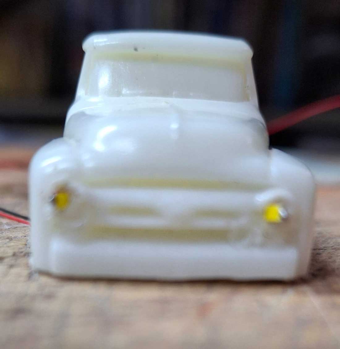
Below is where I did a test run in one of my resin cast vehicles. I drilled out the cast headlight through to the inside of the wheel well in order for the wires to come out underneath before painting it.
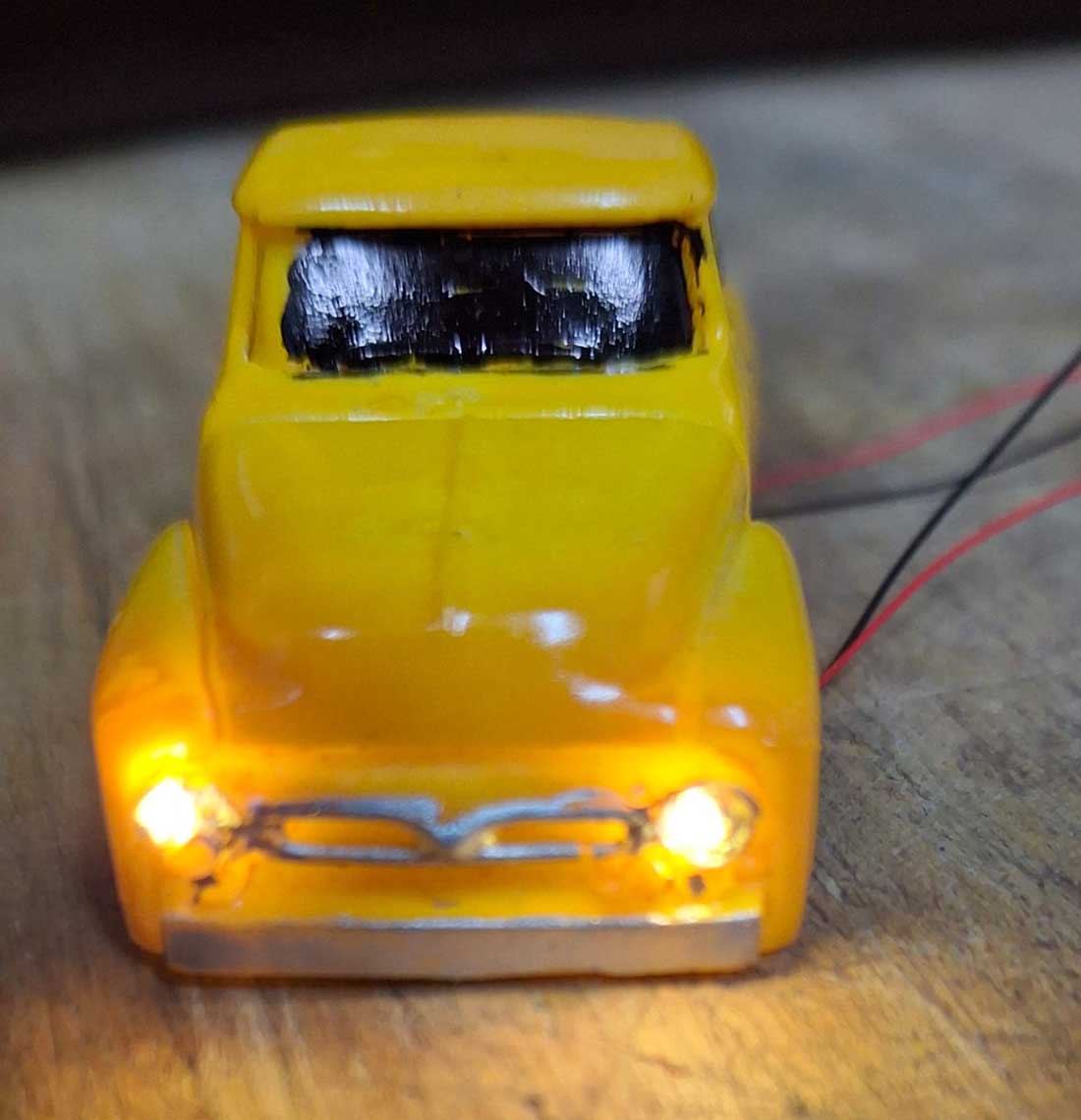
Testing the headlights below.
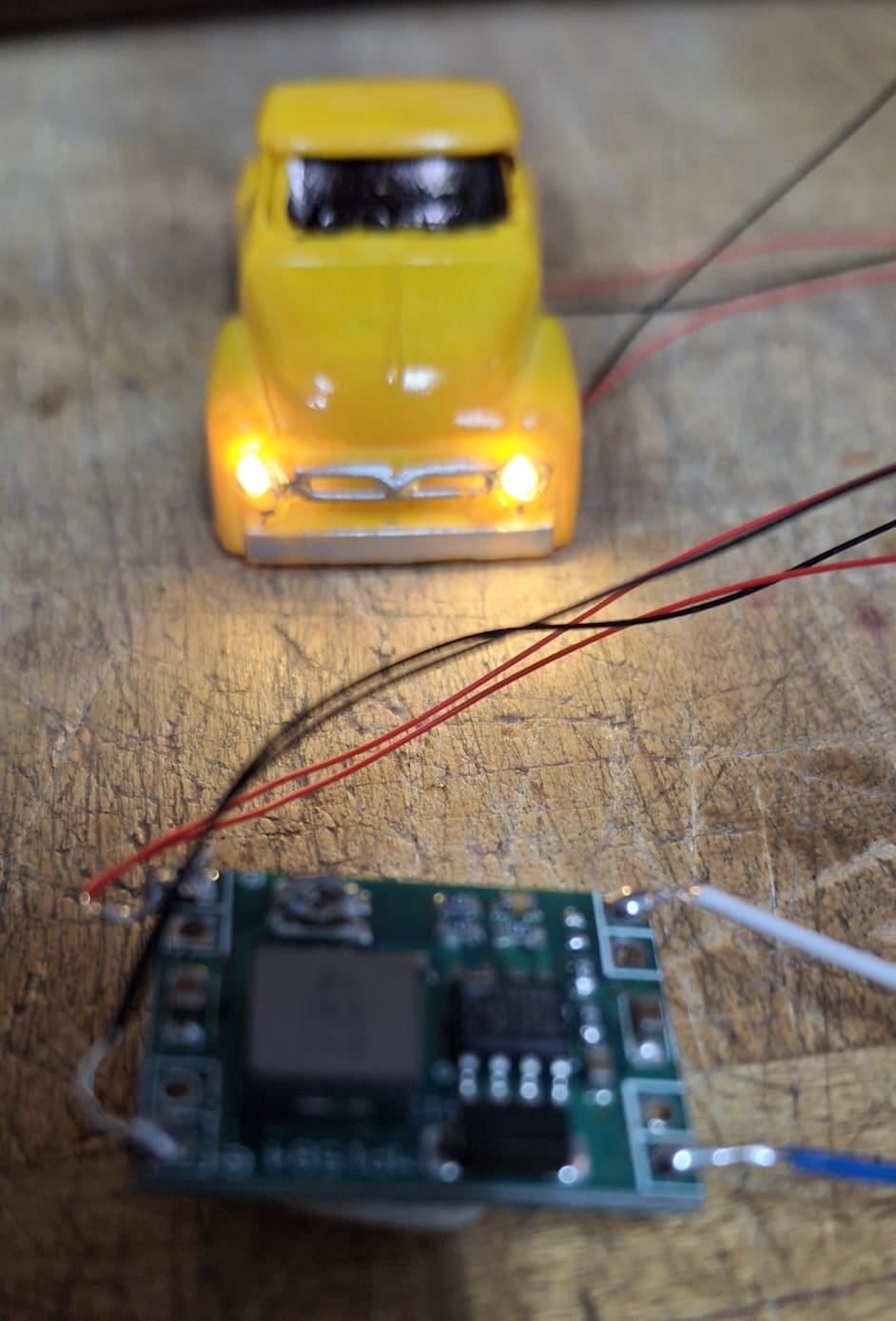
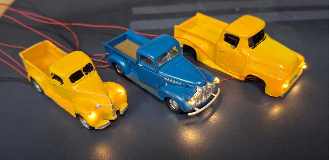
Below, the LEDs are connected via the buck module (shown below)at the bottom and will be mounted under the layout.
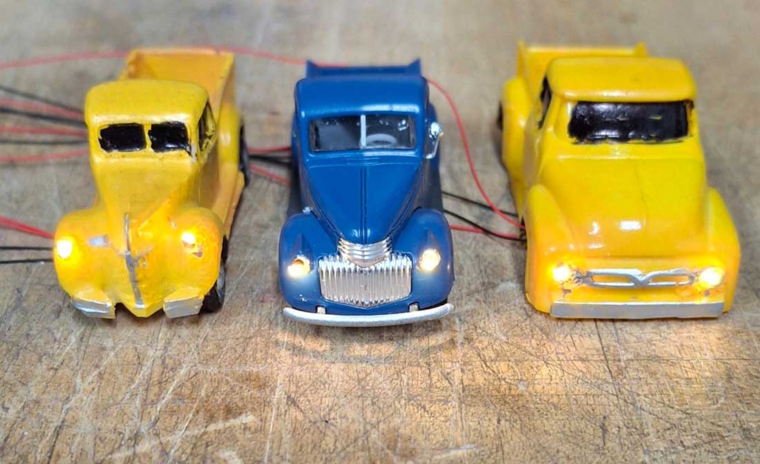
Some more vehicles done the same way.
The buck module can power up to 12 LEDs at a time.
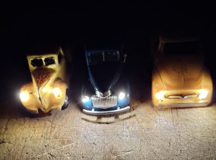
A night shot with the headlights on at 2.7 volts.
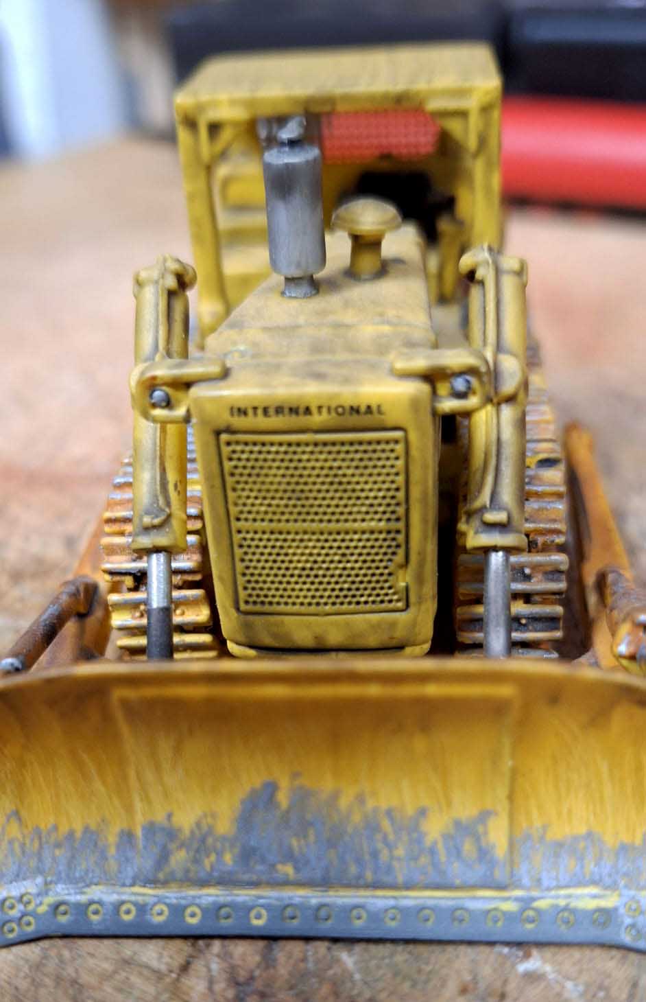
I did not stop there, being happy with the success so far that I decided that a bulldozer needed to have lights as well to be able to work at night.
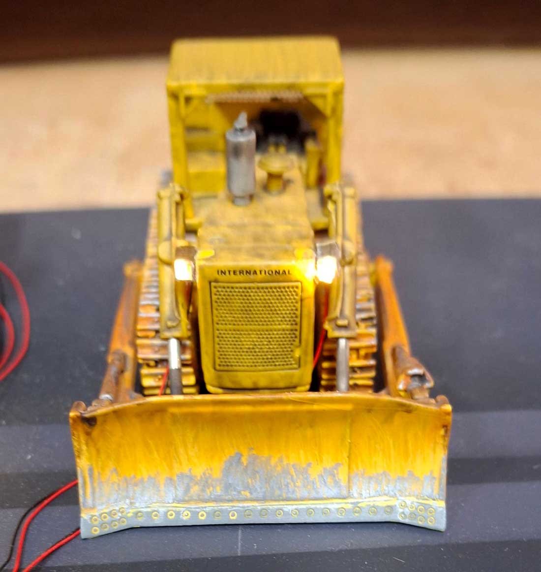
I will also put a LED in the cab so that the operator can see the controls.
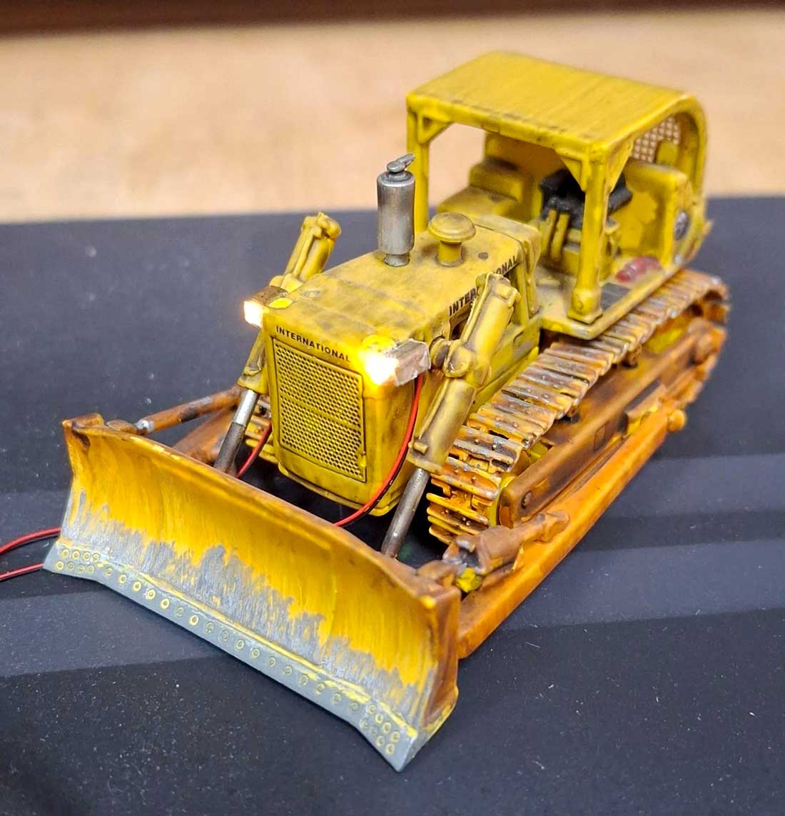
I will hide the wires once placed on the layout.
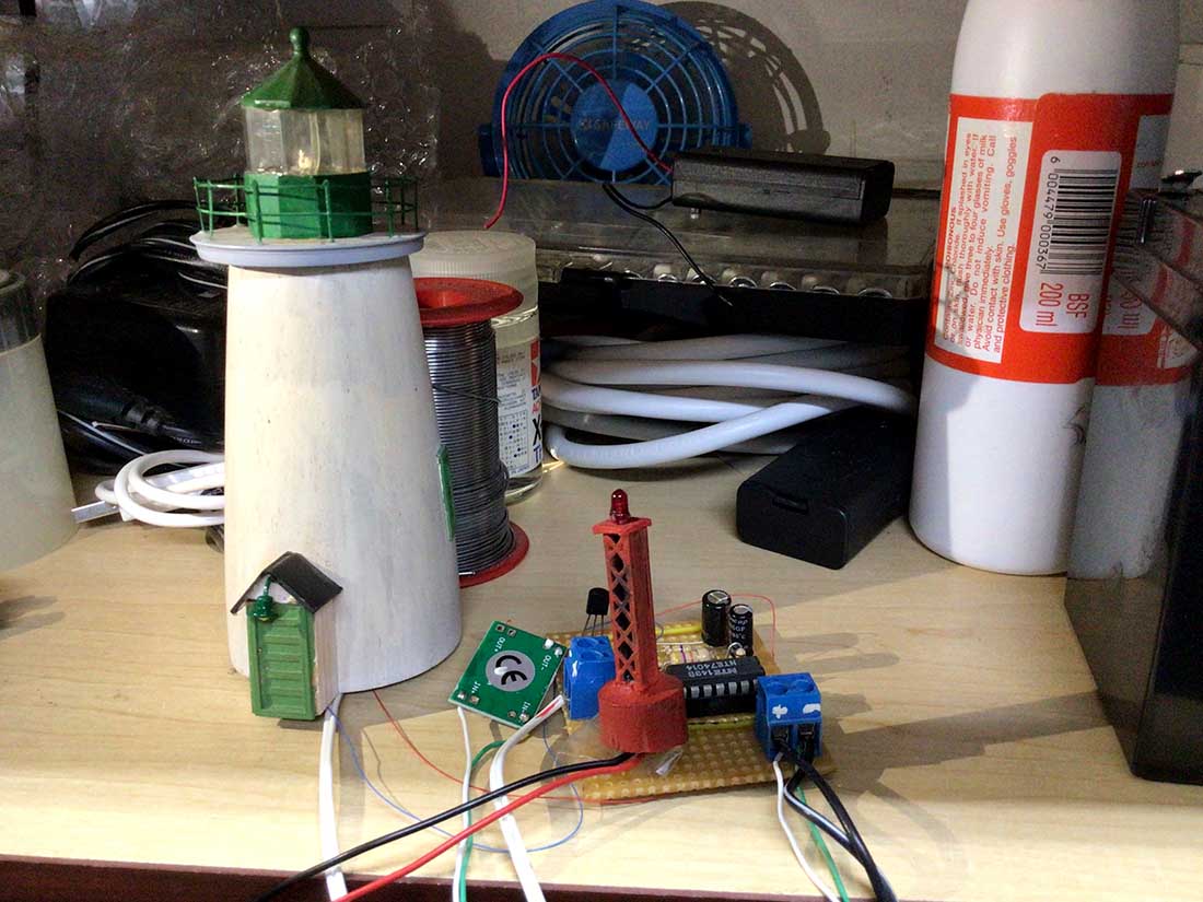
Not to be outdone by the above, I got both my lighthouses working and flashing. A marker bouy was next, added to the flasher unit. The lighthouse and the marker bouy flash at the same time once placed in the harbour.
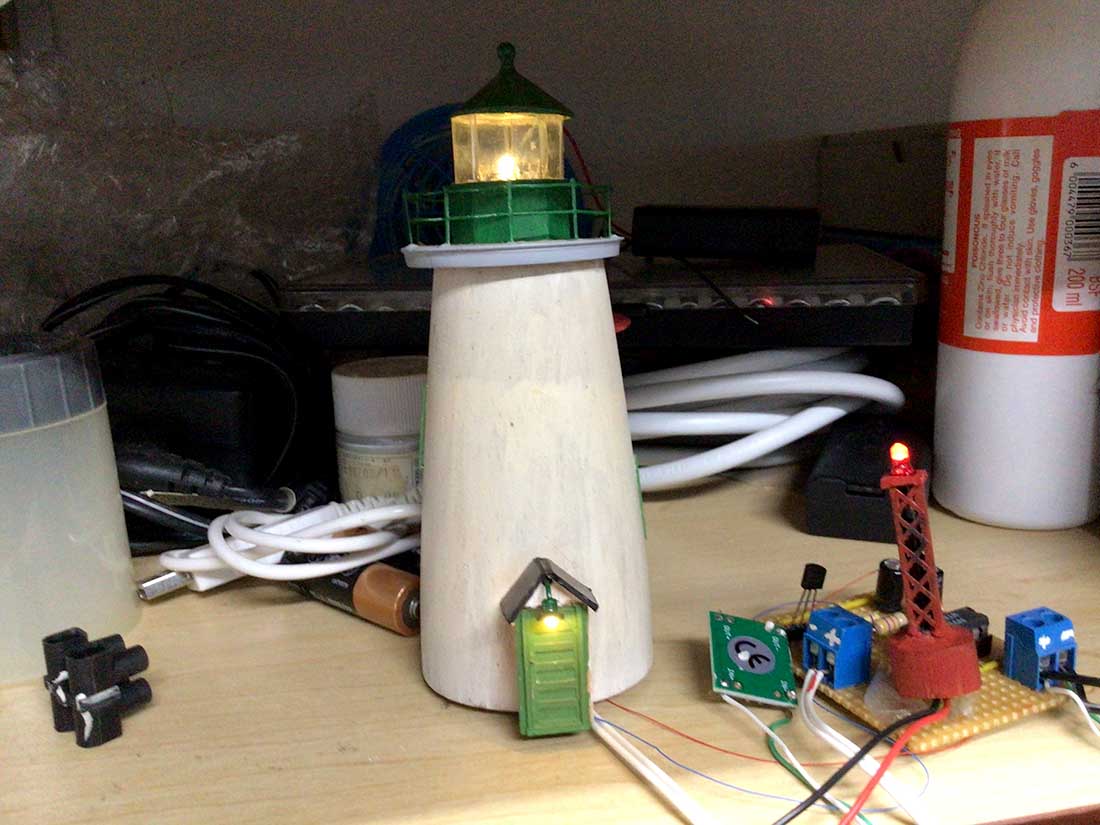
But now I needed the LED light above the door to be constant. Another buck module was added and reduced the voltage down to 2.7v for the correct brightness shown below above the door. The flasher unit is set at 6 volts. Buck modules are cheap enough to use plenty of them under the layout. The green buck module is shown between the lighthouse and the flasher unit.
Unfortunately I cannot show a video of it working.
One thing that I dare not do is spend a lot of time on the Temu website as I see too many things that I want.
I have always treated my hobby with – it is better to have it and not need it than to need it and not have it.
Till next time.
Brian – the HOn3 guy from Knysna RSA”
A big thanks to Brian for sharing his model car light kit.
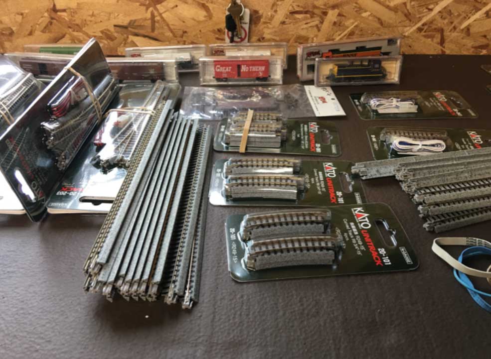
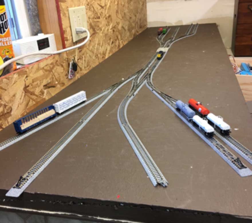
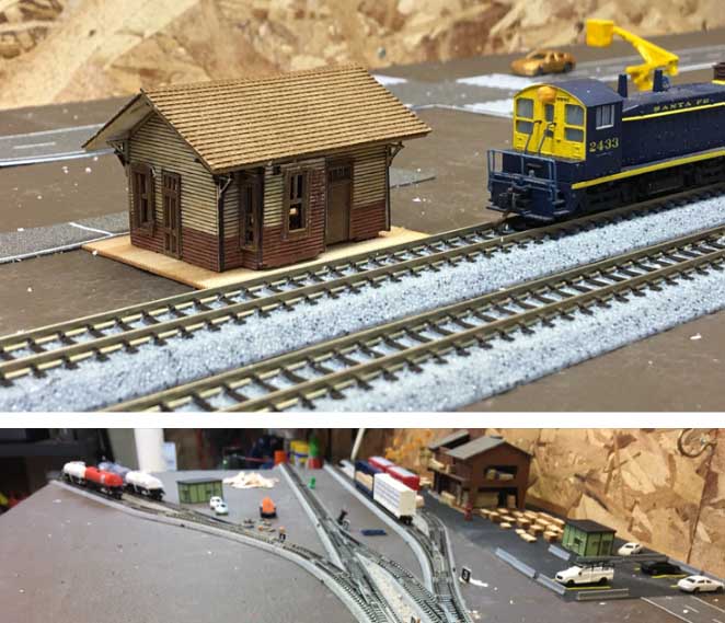
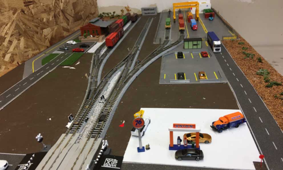
It reminded me of another Hall of Fame post from Taz:
That’s all for this time folks.
Please do keep ’em coming.
And if today is the day you poke boredom in the eye, the Beginner’s Guide is here.
Best
Al
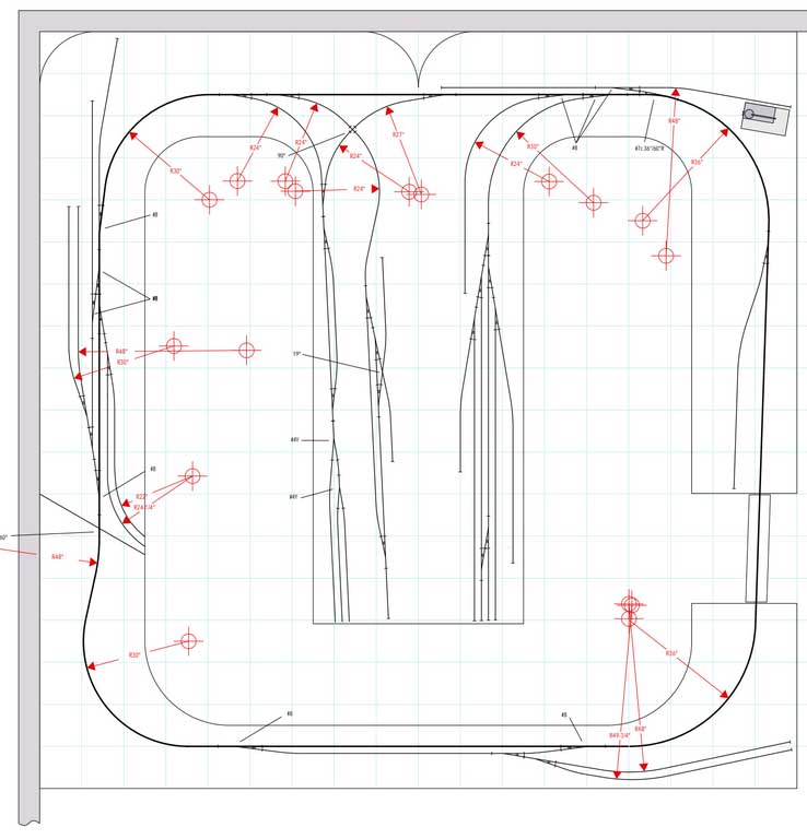
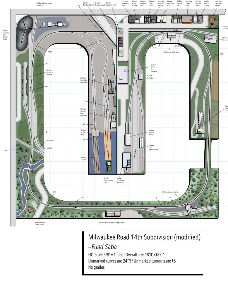
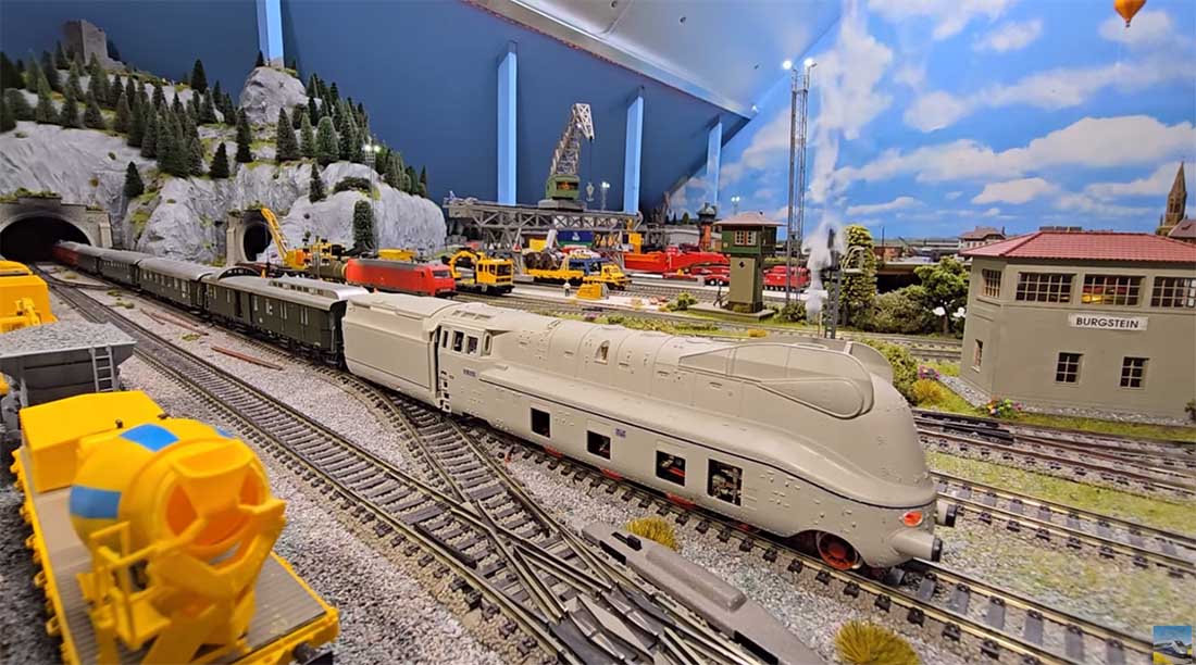
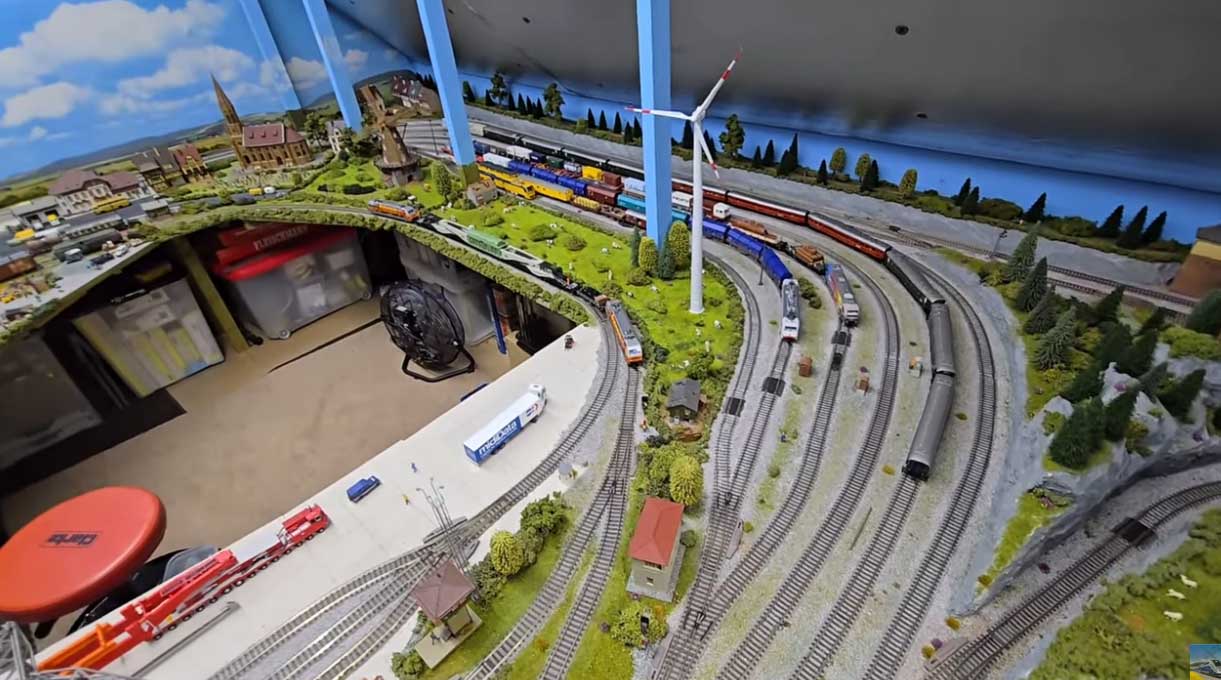
PS More HO scale train layouts here if that’s your thing.

Need buildings for your layout? Have a look at the Silly Discount bundle.