Ben’s been back in touch. Have a look at his HO model railroad lake – he’s got it spot on:
“Hi Al,
It’s been some time since my last post to you. I’ve had some interesting challenges over the past year, which include a bout with pneumonia, basement flooding and a gas line break at the house.
But, now thankfully everything is well and back together.
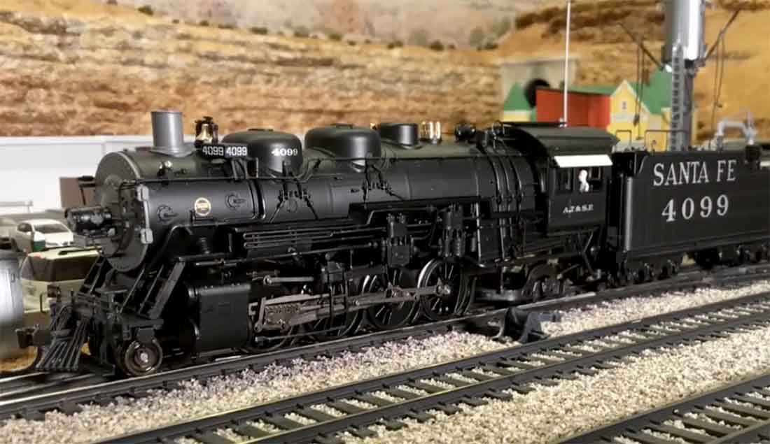
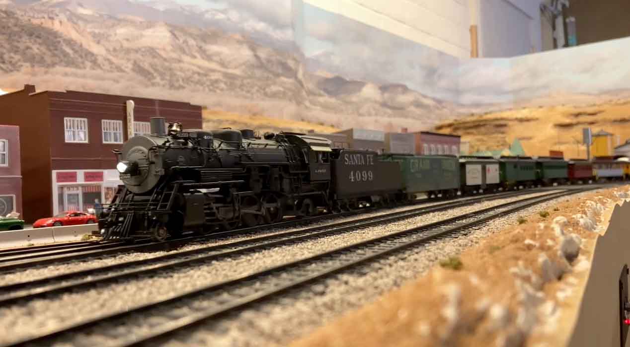
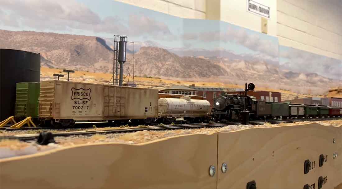
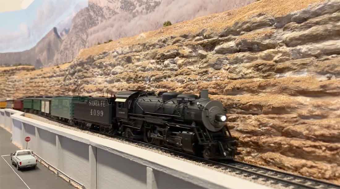
I’ve finished the 9 scenes I’ve been working on in my HO layout for the past 4 years and thought I would share them with you and your readers.
Here are pictures of the 9 scenes.
If your readers are interested, they can view a video I made that shows more detail of each scene, the 3 lines of trains running and other fun stuff.
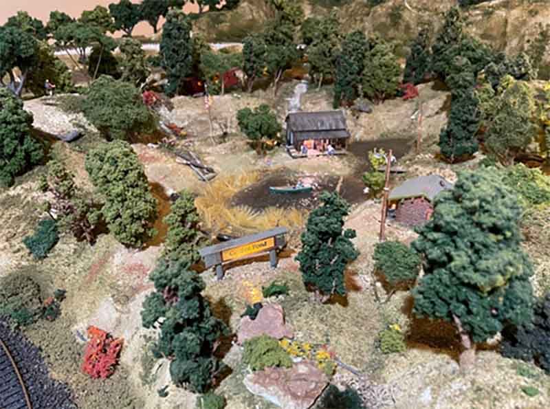
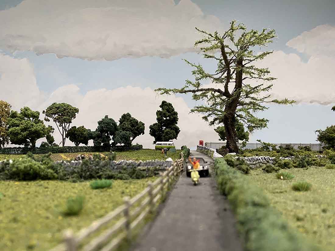
Golden Pond – Created from memories of childhood summer vacations.
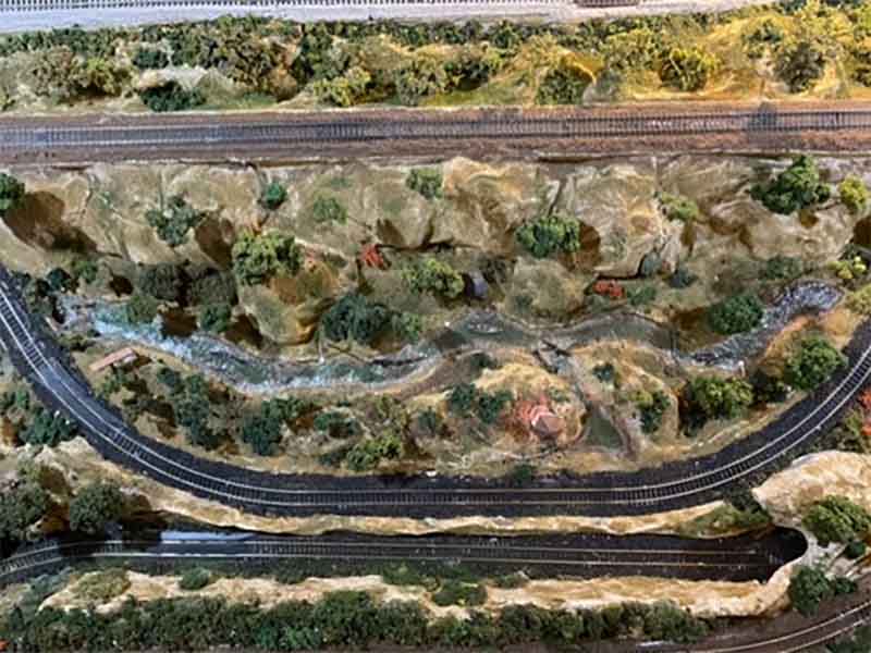
Whispering Creek – An enhanced vision of a creek near our home.
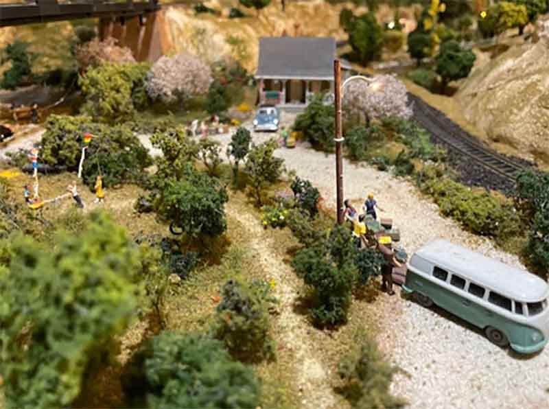
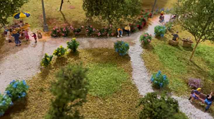
Grandma’s House at Grill and Chill Park – Summertime fun when I was a teen at the local park.
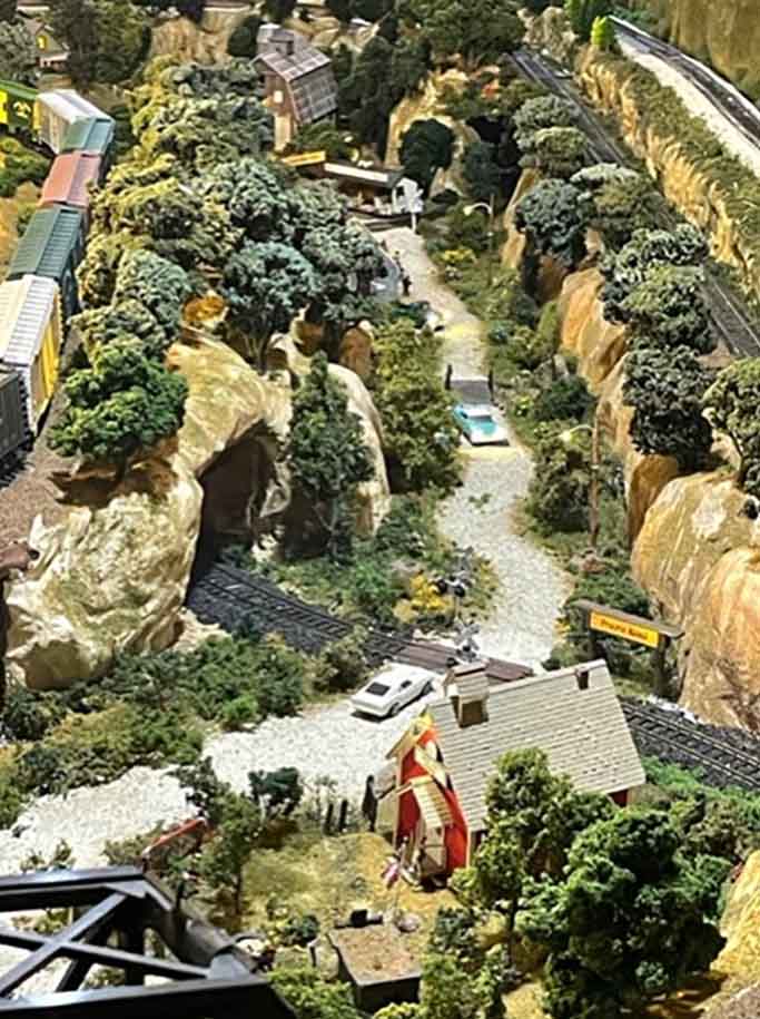
Hazel Dell School and Prairie Road – One room schoolhouse I attended and the road leading to the farm.
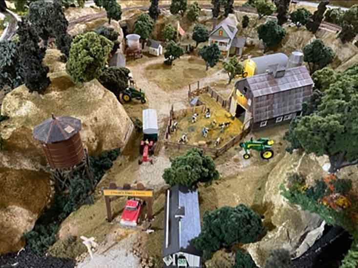
Olson’s Dairy Farm – Childhood memories of life on the farm.
Shelby’s Garden – Named after and created for my wife, who loves to garden.
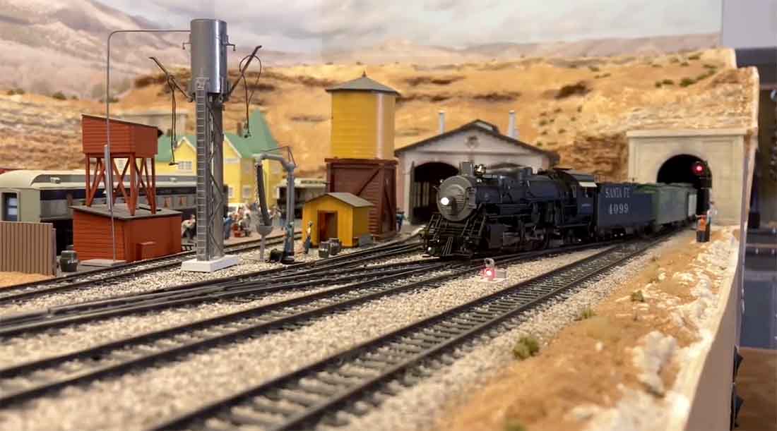
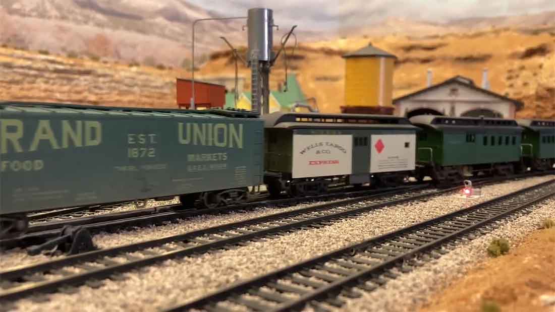
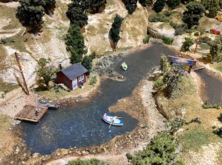
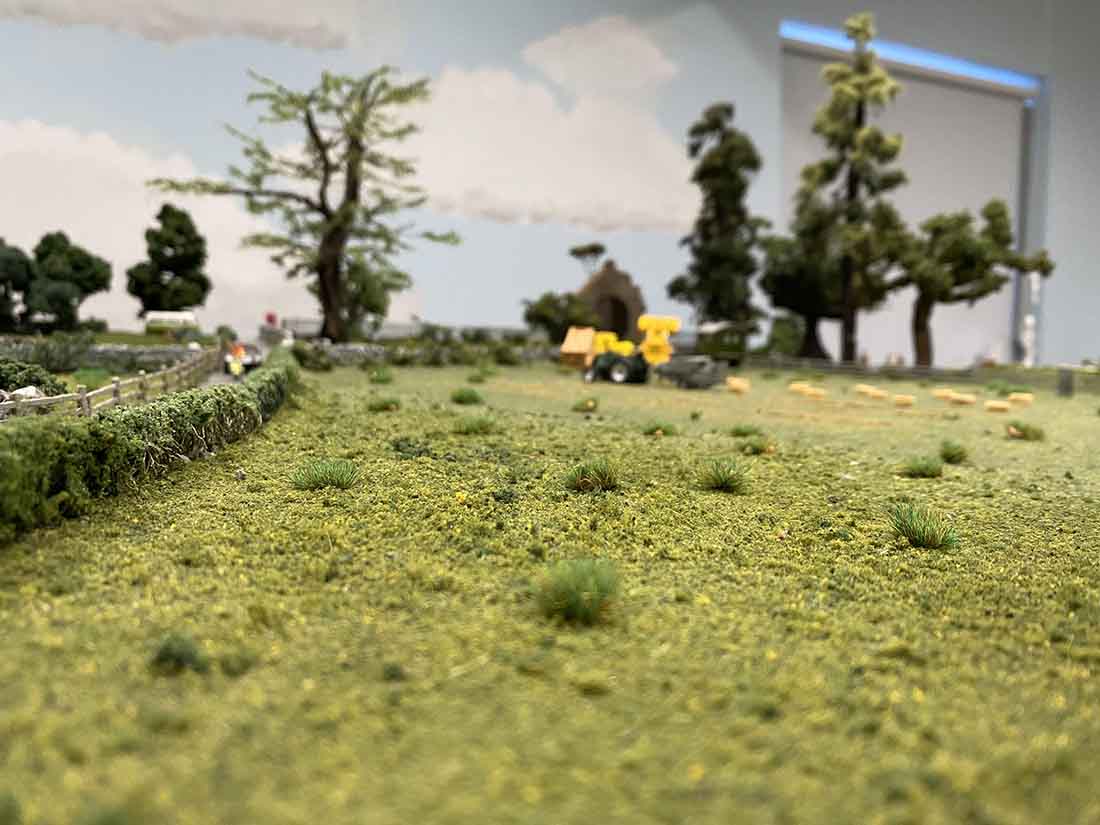
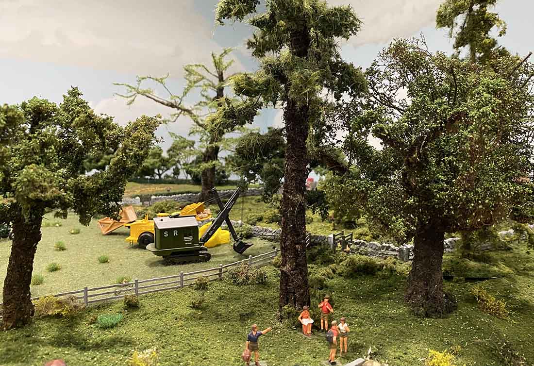
Lake Shelby – Imaginary mountain lake scene.
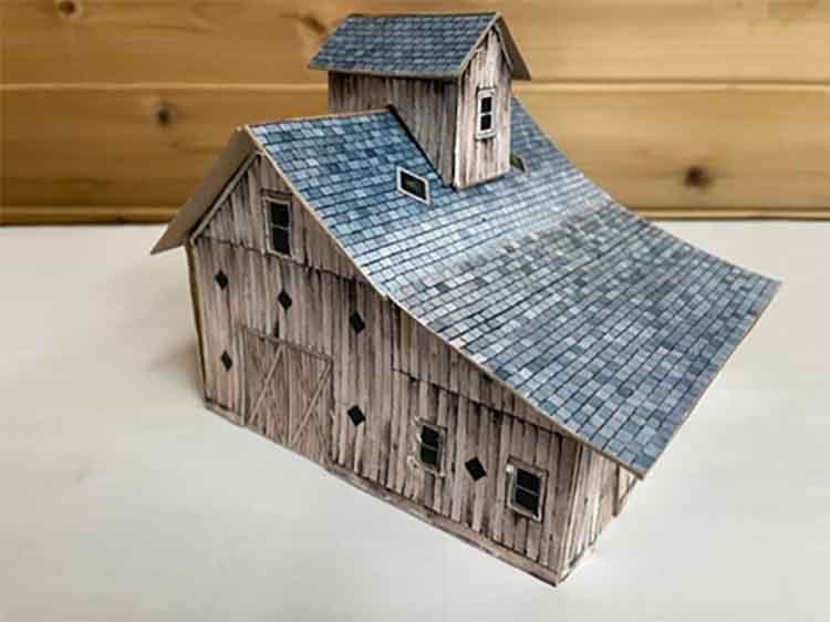
Barn Made From Al’s Beginner’s Guide – What fun!
The last picture is of the barn I made from downloading your Beginners Guide. It was my first attempt, so it’s not perfect but it was a lot of fun to make!
Thank you for all you do in posting and sending out everyone’s projects, pictures and such!
Ben From Chicago.”
A big thanks to Ben – a really nice HO model railroad lake there.
His video is very good too. If you’re toying with the idea of making a start, it’s well worth watching.
If you’d like to see Ben’s other posts on his railroad:
Peter’s been in touch with his suspended train track:
“Hi Alistair.
Starting a new venture with HO scale trains. Had plenty of room in NJ basement for the O gauge, but when I moved to FL, alas, no basement. So, I had to sell all of my O gauge trains.
Having seller’s remorse, I decided to go with HO having a smaller footprint but the problem was where to put it? What room could I use to have a 12′ x 8′ layout?
The garage of course, but the motorcycle and car needed housing also.
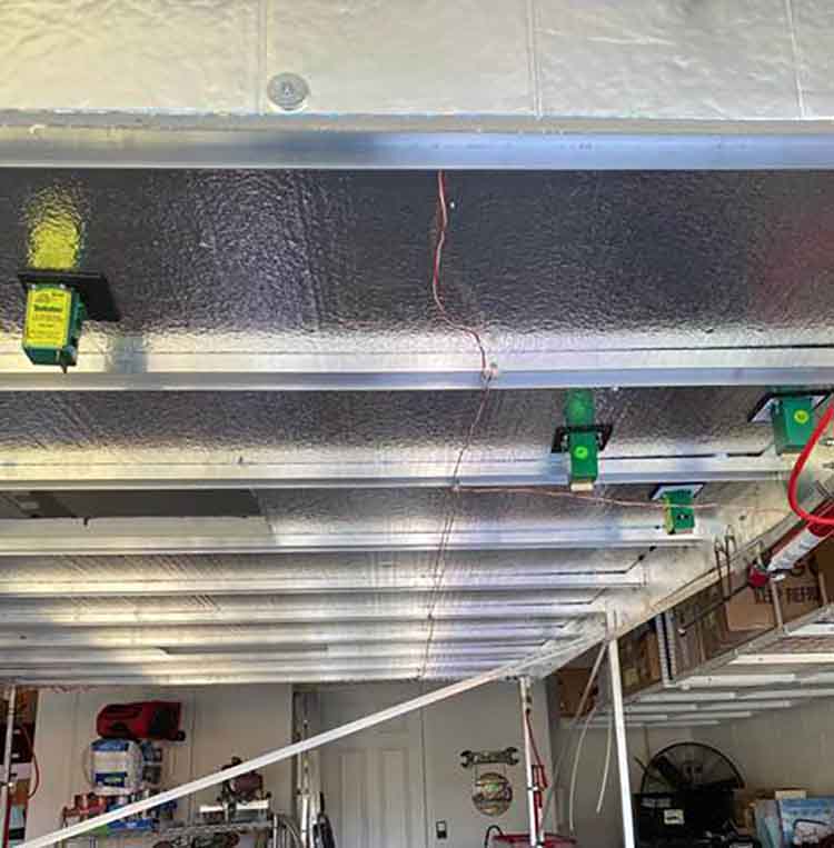
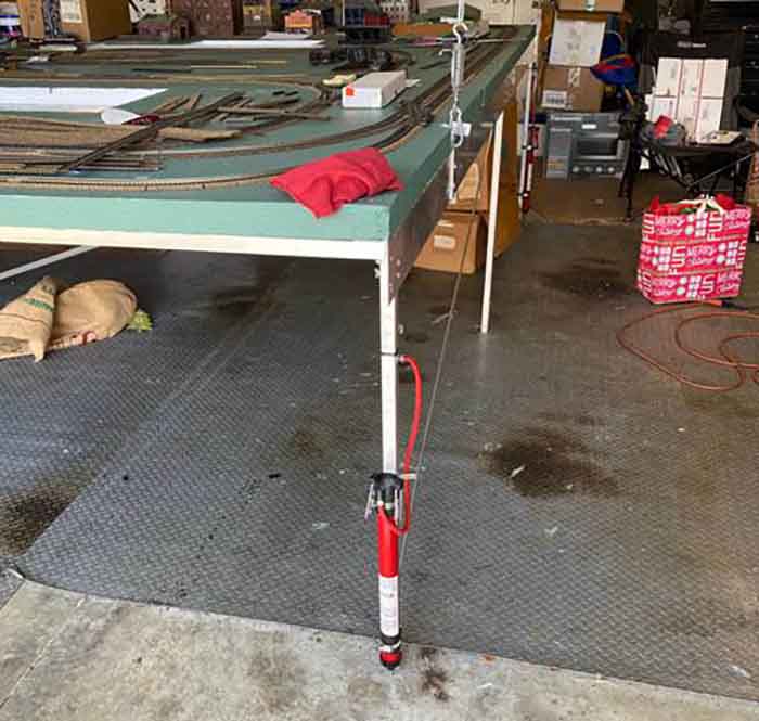
Solution: Build a platform and raise it to the ceiling when not needed. I built a 12′ x 8 foot frame out of aluminum to keep the weight down instead of using wood.
The base used was 2″ Styrofoam 4′ x 8′ sheets. Glued them to the aluminum and painted them green to start.
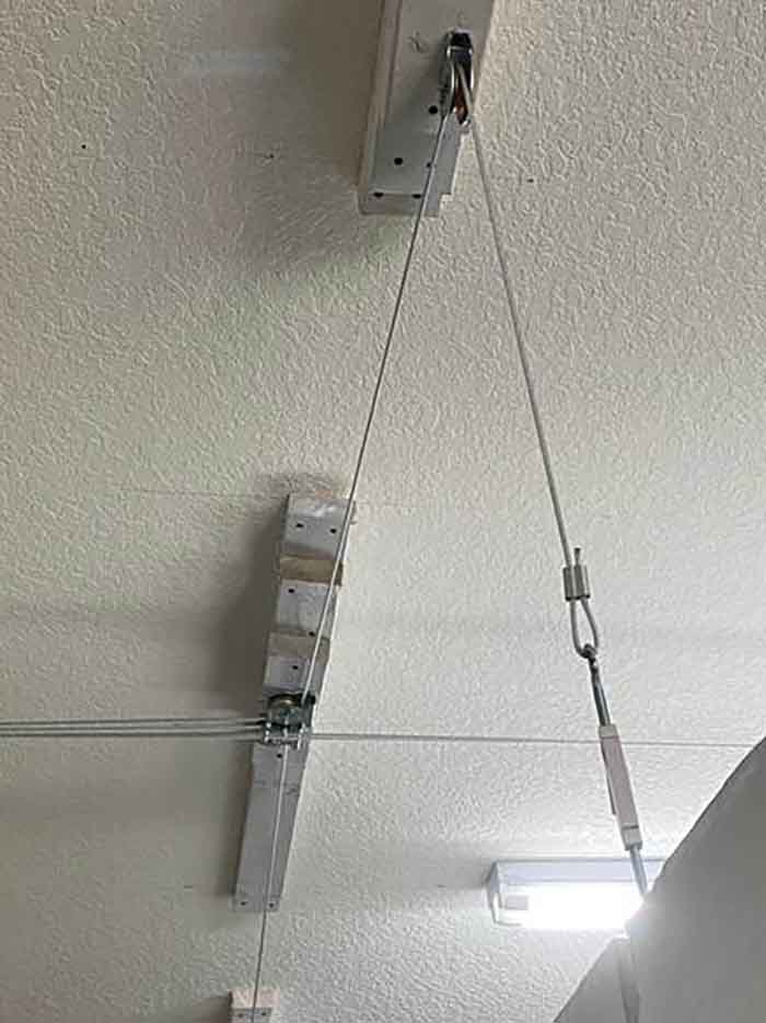
I used a 110v electric winch and pulleys to raise and lower the platform. Bolted to the concrete side wall and used twisted cable rated at 600 lbs. to make sure the load would be carried.
However, the winch lifting this light a load moved very fast and would hit the garage floor with a vigorous thump moving the cars and accessories all over the place. I needed to slow it down.
Solution: Hydraulic shocks. But car shocks were designed for heavy weight. Found the answer at Ace hardware; bicycle pumps. Removing the handles, I attached them upside down to the 4 legs of the table.
I inserted a valve system that I could adjust to limit the amount of air being released thus slowing the touchdown. It now takes about 57 seconds to travel the final 6 inches or so and saving the location of the trains components.
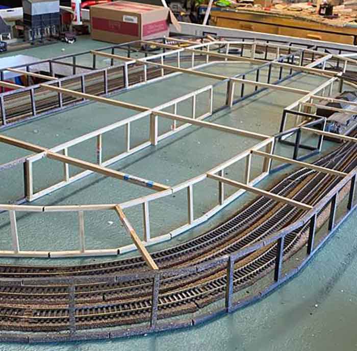
Now starting to lay tracks and building a subway system in the center.
I easily cut out access points in the styro to get to the middle of the layout when needed. Will plan a farm or something that can be easily moved from under the table without disturbing the diorama. Pictures will be sent as I continue further.
Peter”
A big thanks to Peter for sharing his suspended train track – there’s been quite a few over the years: