N scale layout 32×64

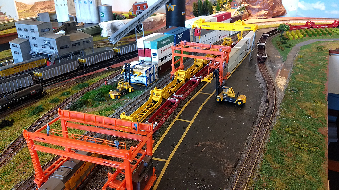
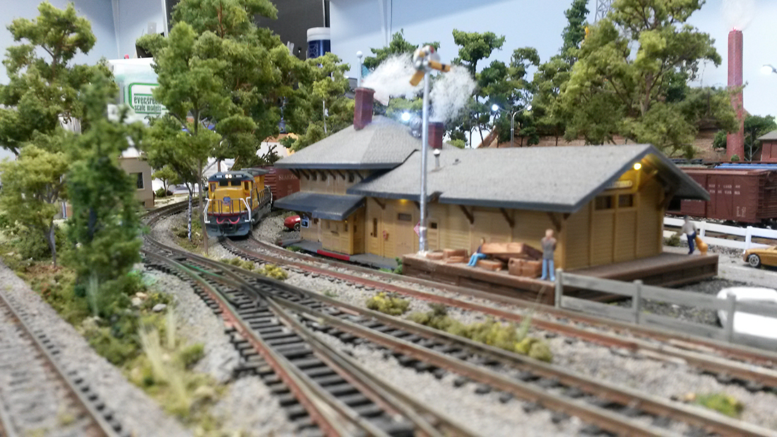
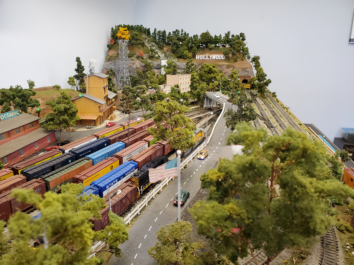
Harry’s been in touch again with his N scale layout 32×64.

If you want to get up to speed, here’s his last post.

“Hi Al,

It’s been quite a while since I sent in photos of my layout, several years by my count, so I don’t know if you remember.

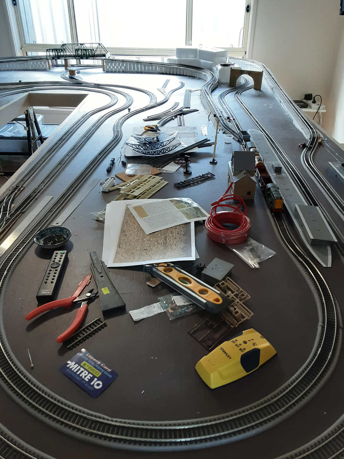
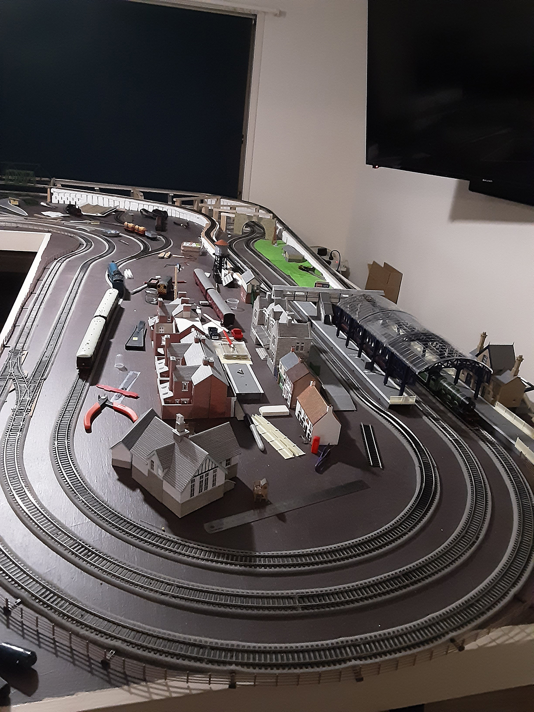
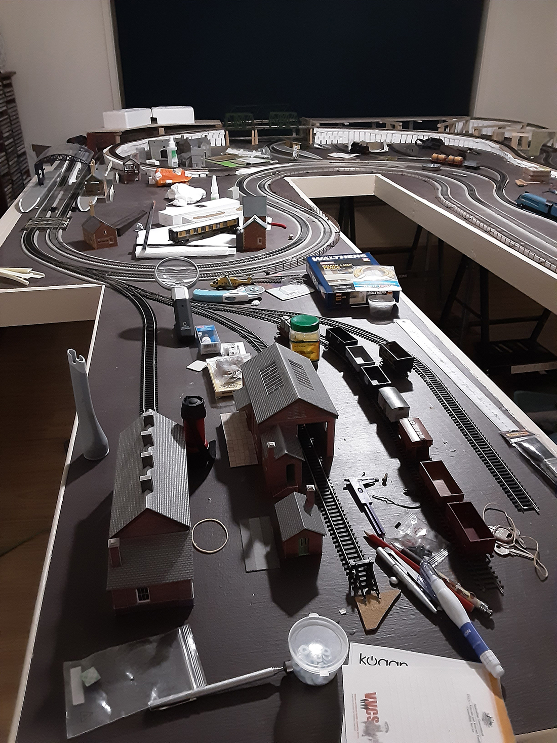
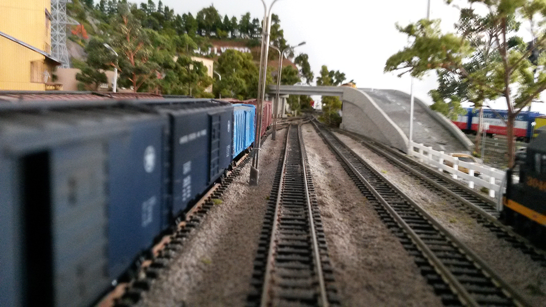
I’m a retired aerospace engineer with a small N scale layout 32×64.

I kinda stopped working on the layout a while back as I was doing a lot of sailing and flying, but I sold my homebuilt airplane last summer after 20 years of flying it, and the sailing slowed as well.

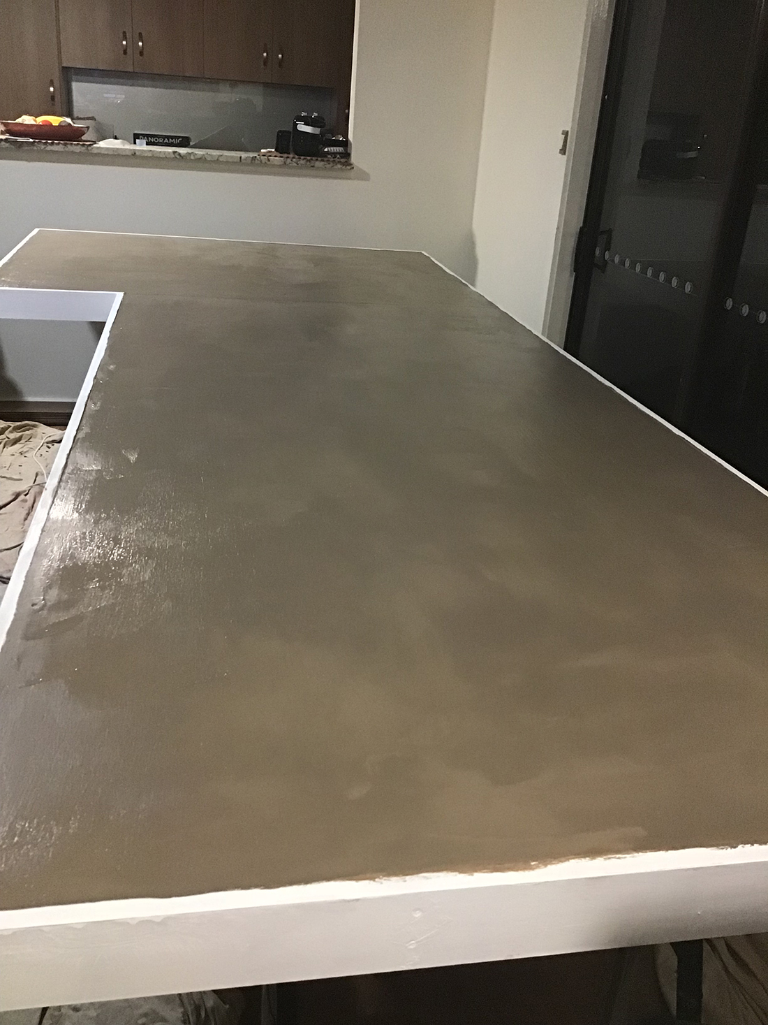
So since I was cooped up, I gravitated back out to the shed and went back to work on the layout.

N scale layout 32x64

I had just recently gotten back to the hobby after 30 years and it all started with your Beginners Guide. You may recall I termed mine a ‘test layout’ since I originally built it in a hurry to test out ideas and new materials in getting back to the hobby after so long and it sort of grew from there.

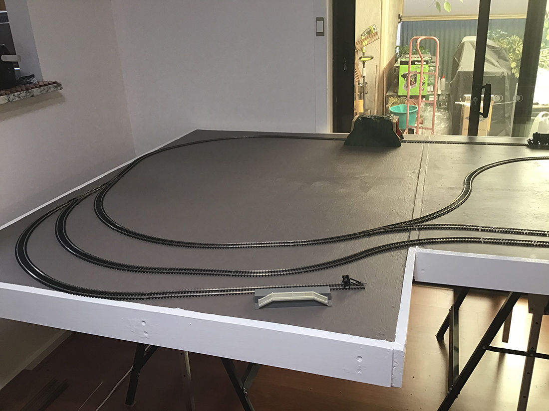
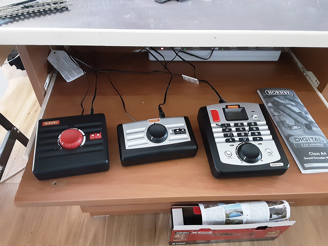
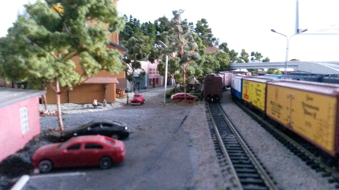
With the advent of DCC and all the low cost microelectronics I was hooked, (re-hooked). Having all the unwelcome COVID-19 shutdown time, and to forestall boredom, I think I made enough trees to reforest the Sahara (in N Scale of course) and I didn’t really expand the layout at all, just kept adding people, trees and Arduinos, sigh. I still consider enlarging the layout to go all around my 8 x 14 foot shed, but I usually just sit quietly till the feeling subsides.

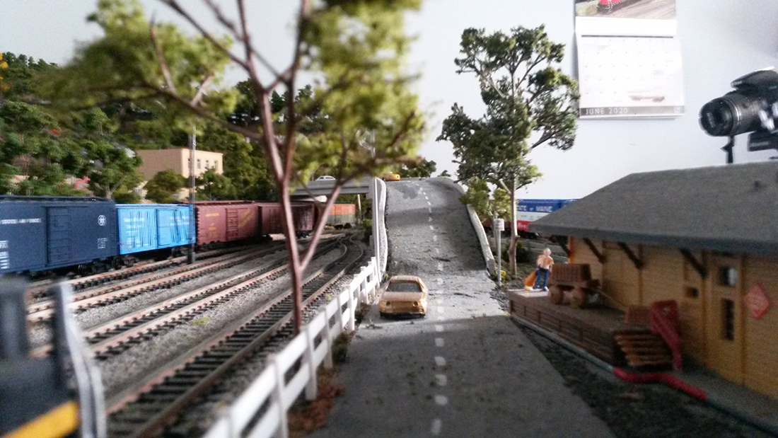
I have gotten into Arduino and Raspberry Pi projects and right now I’m working on a crossing gate system using Arduinos. I need to find an old fashioned doorbell with the arm and coil for the sound, but they are becoming quite rare.

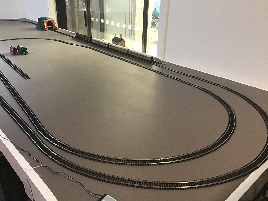
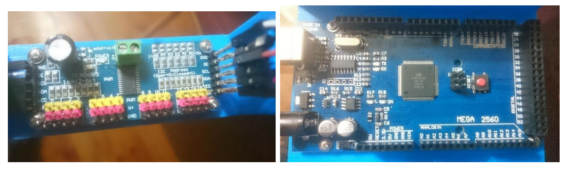
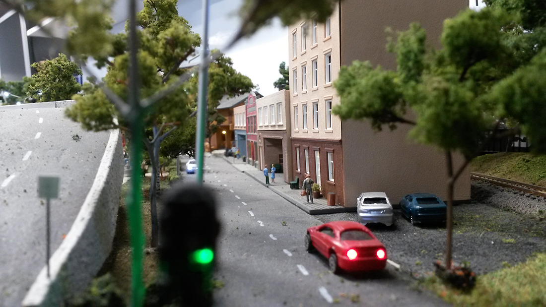
I use a Raspberry Pi to compile and download my Arduino code, so my shed is a computer room as well as a train room, but it keeps me from going mad… I think… The layout itself has 6 Arduinos beneath, controlling the main street traffic lights, campfires, arc welder in the factory, hotel room lighting and several other tasks as well as controlling the 17 turnouts on the pike.

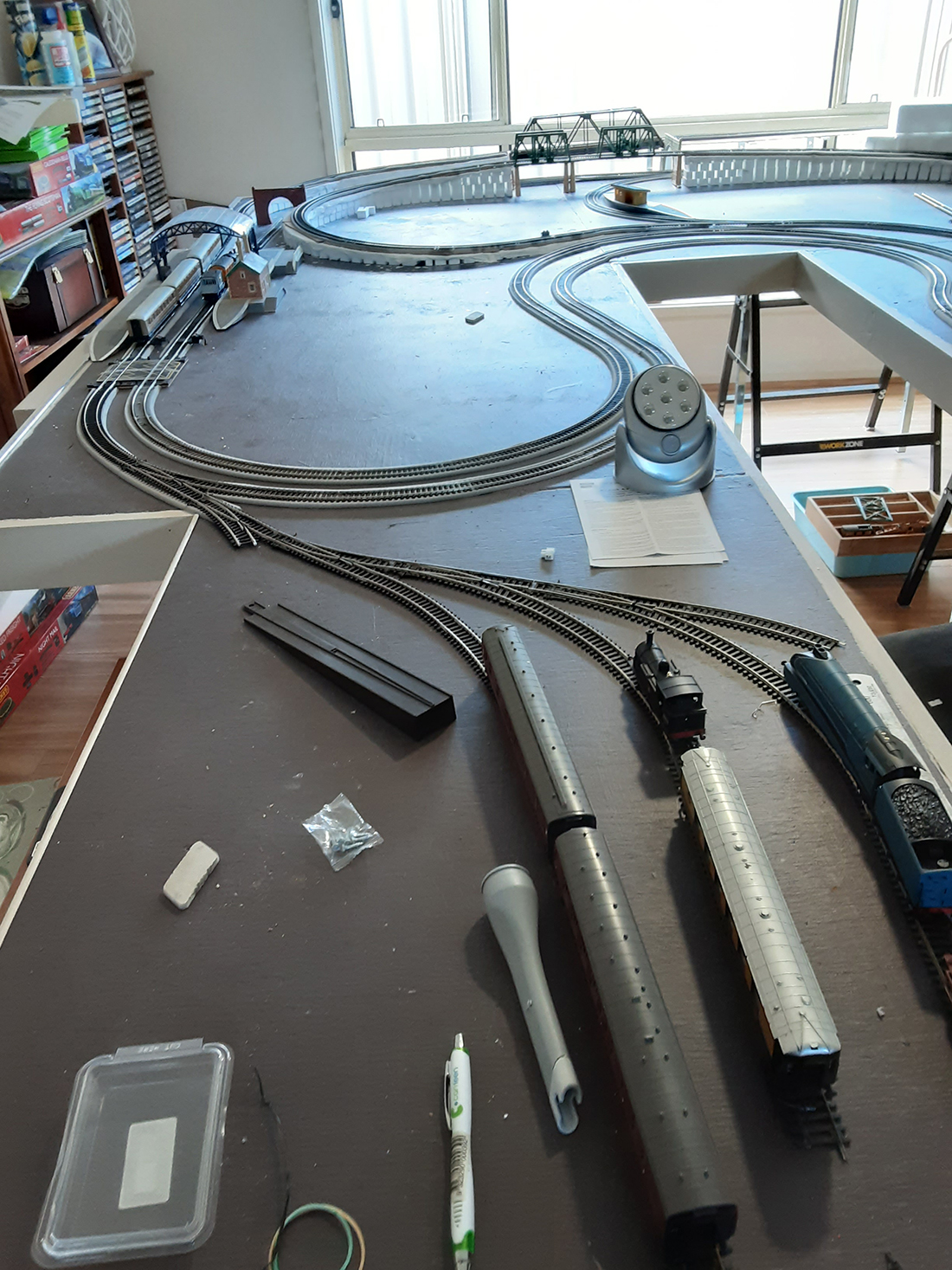
I will end up using two Arduinos to control the crossing gates since they don’t multitask well, but at a cost of $2.50 ea US I can afford to be generous with my distributed processing. After 25 years of writing code for inertial guidance systems, it’s fun to play with these things. I was retired for over 5 years before I discovered them and my coding skills were getting pretty rusty. It’s coming back, sort of….

It’s been so long since I sent those photos I don’t even remember which photos I sent and I don’t think that article is on line anymore, so I’ve attached a few photos I’ve taken recently which I’m sure won’t be duplicates. I may send them in several emails since I don’t know how much the web will tolerate.

Keep up the good work and stay healthy.

Sincerely

Harry”

N scale layout 32x64

N scale layout 32x64

N scale layout 32x64

N scale

N scale


A huge thanks to Harry for sharing his N scale layout 32×64. Loved the narrative just as much as the new pics. Stunning stuff indeed.

And I’m only human – when people say kind things about the Beginner’s Guide, it really does put a smile on my face.

Now on to Kim:

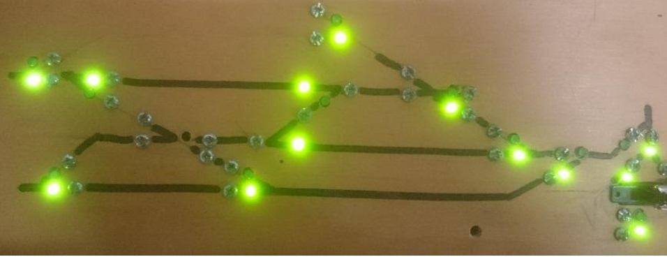
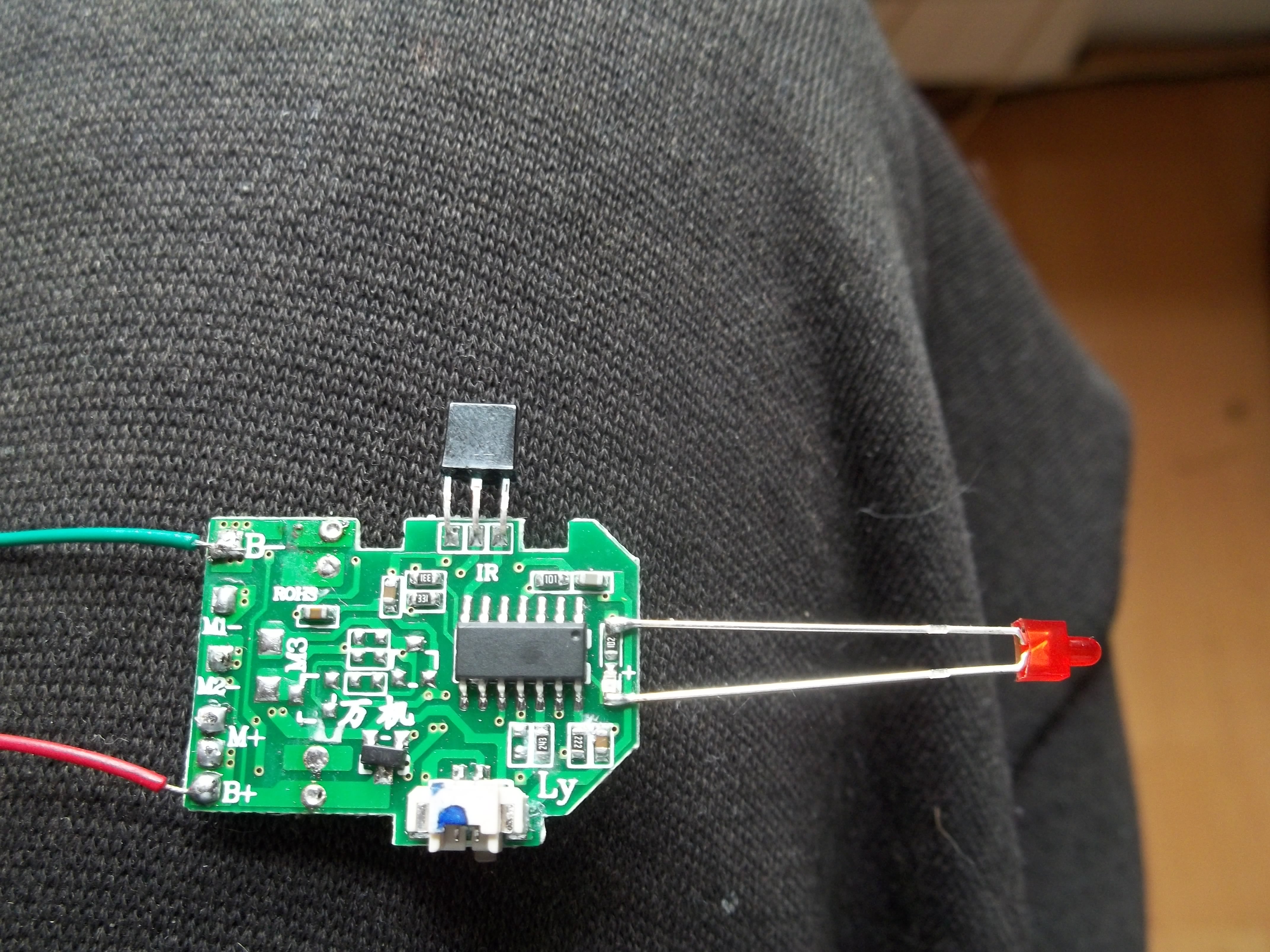
“Hi Al. here is an idea for police strobes, emergency strobe, warning, or even a end of train device.

I tied into the mini power strobe that was there. It would destroy the board if I tried to remove it so I tied into it. I added a foot long wire with no power lose. I am using the rechargeable battery that comes with it and can recharge it. Will last a very long time strobing. or can use a rechargeable phone battery say 2.7 volts doesn’t take much power so don’t over power it with high voltage.

The PC board came out of a mini helicopter. So if you find them in garage sales cheap buy them. If you don’t have strobe lites on your train and want them and don’t want to hook to a decoder or isn’t any decoder think about using these boards. Small anough to fit into a Hoscale car or truck. So when I garage sale picking will look out for these toys. I am sure I can tie into the board to operate mini 2 servo’s say for a crane or something. another junk idea.

Take the led and add a very very tiny bit of solder on the tips of the led. Dont over heat the led – be fast. If you look carefully you see I put one post to the resistor and the other post to the mini led that is on the board. Sort of tie into it.

The tiny original led will be left alone as it would destroy the board trying to remove it. Just tie into the tiny one. When you go to solder the led be fast at it when tying into the led or you will over heat it. I removed the tiny battery that came with it to attach a few longer wires for power.

Max power should be 3 volts or burn the board or blow something. The board came with two other led’s one on each side that I unsoldered as I didn’t need them. Hope this helps

Kim”

model train strobe


(Kim’s post reminded me of Steve’s: Model railroad signal wiring.

A big thanks to Harry and Kim.

That’s all for today folks.

Please do keep ’em coming

Best

Al

PS Latest ebay cheat sheet is here.

PPS More HO scale train layouts here if that’s your thing.


printable buildings

And there’s the Silly Discount bundle too.

Flying scotsman model train

Fred’s been in touch with his Flying Scotsman model train:

“Hi Alistair,

As a follower of your posts for the last couple of years, I thought I might show you my progress, so far, having been given a “Flying Scotsman” for my 70th birthday, two and a half years ago.

I started up with a blank canvas building a L shape in the family room of our Adelaide, South Australia home. After a year, I realised that the space wasn’t big enough, so I convinced my wife we need a “sea change” and moved to Victor Harbor, again in South Australia which had a room just the right size for a larger set up, so dismantle what I had built and start again in our new home.

This time it is a U shape, with the sides made up with 8 feet X 4 feet sheets and the bottom (or top – depending how you look at it) measuring 9’ X 4’ and a 1’ walkway in between. I bought a stack of Aldi Multi-purpose supports when they were half price, made the frames with 3×2 structural pine and the board is Marine ply.

I am working on Era 3 UK and all my locos are Hornby OO. There are 2 tracks operating on DC around the outside and the inside line is DCC and splits into 2 after main station where one goes under the mountain (to be built) and the other around the front of the mountain.

The mountains are under construction out in the shed, at the moment as are many of the buildings. I am finding it difficult sourcing many of the specialised buildings and structures in Australia as stocks run out and are not being replenished from overseas very quickly, due to the COVID-19 virus shutdowns.

I attach some photos -The first 3 are my original start of the layout, the next 2 was the new layout as it stood in April, the next 2 as it stands today and the last is my control desk (work in progress).

I will of course keep you informed as I progress.

Cheers,

Fred”

Flying Scotsman model train

Flying Scotsman model train

Flying Scotsman model train

oo scale


oo scale

oo scale

Flying Scotsman model train

Flying Scotsman model train

A big thanks to Fred for sharing his Flying Scotsman model train.

I like posting layouts that are just starting to take shape, because it shows in spades this hobby is all about making a start.

That’s all for today.

Please do keep ’em coming.

And don’t forget, the Beginner’s Guide is here if you want to take your first step towards your own layout.

Best

Al

PS Latest ebay cheat sheet is here.


Arduino model train projects

Slowly but surely there are more and more Arduino model train projects being submitted.

This is how Tim solved a problem with his turnouts:

“Al – I was inspired by a story you published about using servo motors to control turnouts. I did some research after reading this story and considered that using servos might be a viable option to replace the traditional solenoid motors in my current model railway.

I currently use the stud and probe method with nuts and bolts through my baseboard in the design of the track (photo below).

Solenoids were relatively expensive and due to the age of them, there were occasions when they would get stuck.

However, the method of controlling these servos seemed cost prohibitive given the cost of the controllers used to activate them. It seemed to me that the maximum numbers of servos that could be controlled by one control panel was 12 and they were expensive to purchase.

Arduino model train projects

After doing further research (and with the aid of my extremely talented son) I believe that I have come up with a very cost effective solution.

Firstly I purchased an Arduino mega for about AU$14.00. It has 54 inputs meaning that it can control 54 separate servos.

I have hooked the Arduino up to three PCA 9685 16 channel PWM servo drivers. These cost about AU$8.00 each. As the name suggests each board can control 16 servos. They can be hooked up in series so that the full 54 inputs of the Arduino can be used.

The servos cost about AU$2.00 each and with the costs of a power supply, dupont jumper cable connectors (so I could make my own wiring) and aluminium channel to house the servo, each turnout worked out to around about $5.00.

I used a straightened paper clip to connect the servo to the tie bar of the turnout to act as the lever to change the direction of the turnout. There are many internet articles about fitting servo motors.

Arduino model train projects

My son has written some sketches (programs) to control the servo for various Arduino model train projects.

The first sets the servo at 90 degrees.

The second is to control a single servo – it is very useful to determine the angles required to change the point from straight ahead to turn.

The third sketch is to control up to 48 separate turnouts using the PCA 9685.

The input for each servo is the ‘stud’ part of the existing control set up with the probe being connected to the ‘ground’ input on the Arduino. Each time there is a connection between the stud and probe the servo moves in the opposite direction that it last moved.

Previously I had 2 studs per turnout – one for each direction. I now have one per turn out – each ‘press’ changes the turn out to the opposite side. The same results could be achieved by using press buttons although the wiring would be a little harder given that every button would need to have a common ground wire (this is achieved in my system with the probe)

The sketches (particularly the last one) allow for individual angles to be provided to each individual servo and the speed of the servo to be adjusted so that they change as fast or as slow as the modeller desires. They are down loaded to the Arduino and once downloaded the Arduino executes the program each time a button is pushed.

Replacing existing turnout motors was very simple. After removing the existing motor, I put the paperclip through the tie bar from above. I put a 90 degree bend in it so that it wouldn’t fall through. The aluminium channel was fitted from below the baseboard. I passed the paperclip through the appropriate hole and temporarily stuck the channel to the baseboard with a piece of doubled over electrical tape. After checking that moving the paperclip from side to side operated the turnout, the aluminium channel was secured to the baseboard using 2 screws.

I then put a ‘z bend’ into the bottom of the straightened paperclip, attached the servo motor and pushed it up into the aluminium channel. After checking that the servo worked the top of the paperclip was trimmed back to the tie bar level.

The LEDs have been wired to the side of the turnout. The inner rails of the turnout have been isolated so that the LED only comes on when the blade of the turnout is closed. That way I can see the direction and know that the blade of the turnout is closed.

This might impact on some business of the companies that have made turnout controllers but this system is far cheaper and thanks to the sketches already written it is very easy to install and control servo motors.

Hope this can be of assistance to the wider modelling community.

Regards,

Tim”


Now on to Cassio.

I don’t really publish pics on their own, but this one had me looking at it for a while, so I thought, why not?

You can see Cassio’s last post here.


“Hi Al , just had a day out up in North Yorkshire to see some Steam.

Thought some of the members might enjoy, as I say some saying they see too much of DMR with trains running.

Regards

Dave”


I often ask whether I’m posting too much of Dave’s stuff. I have to say the people who say ‘no’ are in the majority by a country mile, so I’ll continue to with Dave’s Model Railway.

That’s all for today.

A big thanks to Tim – I’m seem to be getting more and more Arduino model train projects, like Keith’s and John’s.

That’s all for today folks.

Please do keep ’em coming.

And don’t forget, if you want to take your first steps towards your own layout, the Beginner’s Guide is here.

Best

Al

PS Latest ebay cheat sheet is here.