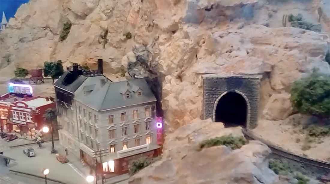
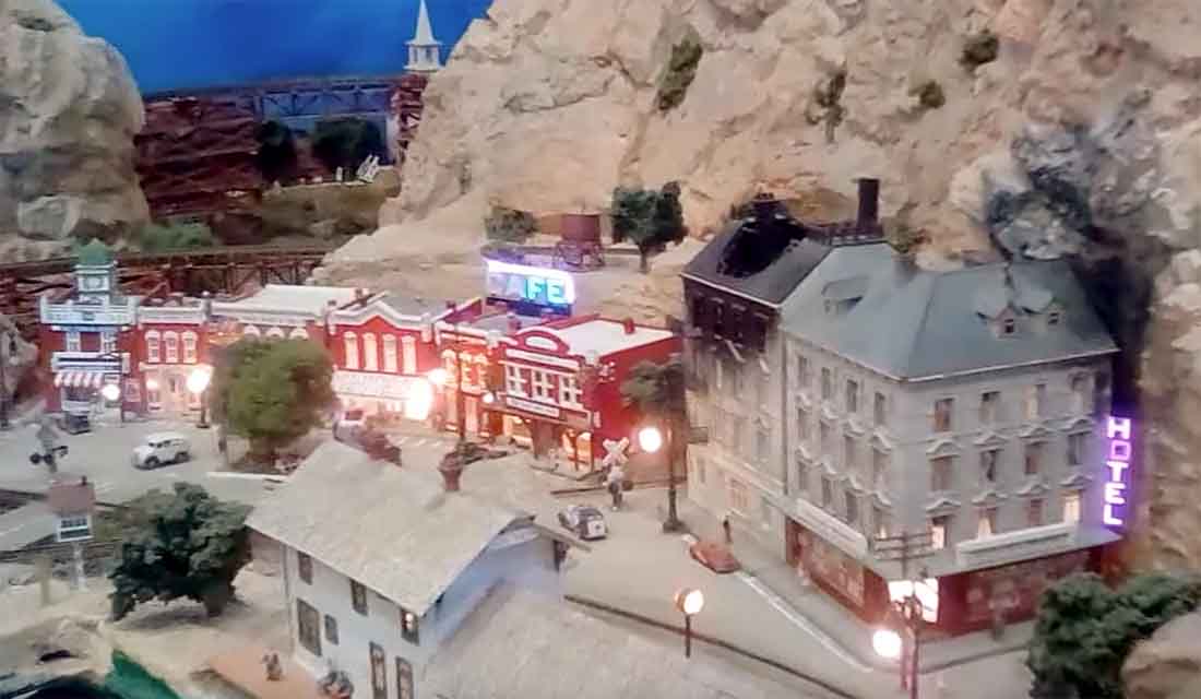
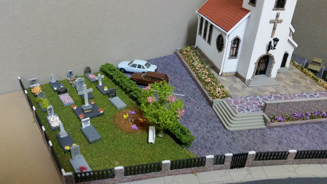
Paul’s been in touch with his N scale hotel scene:
“I have a brief video of my layout (at least a portion of it) that I would like to share on your site.
I live in Arizona and took 5 years building it after details both common and unique to Arizona and just made the video to share my most recent addition of computerized n scale neon signs.
I’m a retired aerospace engineer (still working with electronic companies in my retirement) so the electronics plus the extreme detail have always appealed to me.
Best regards,
Paul”
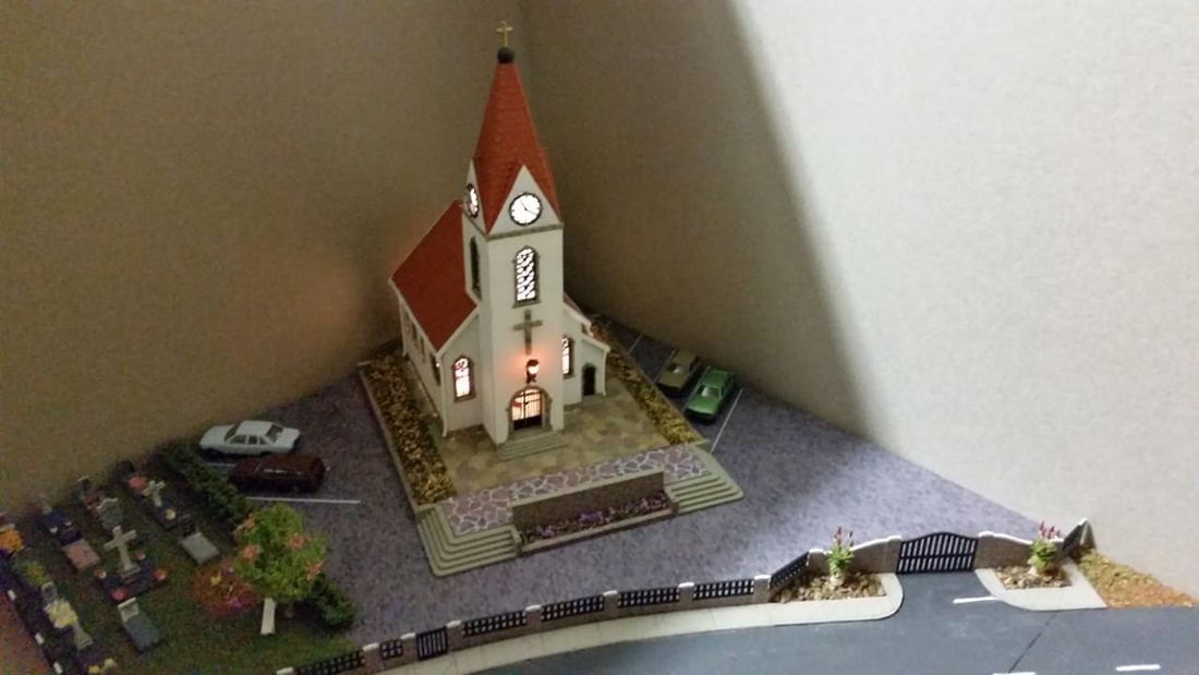
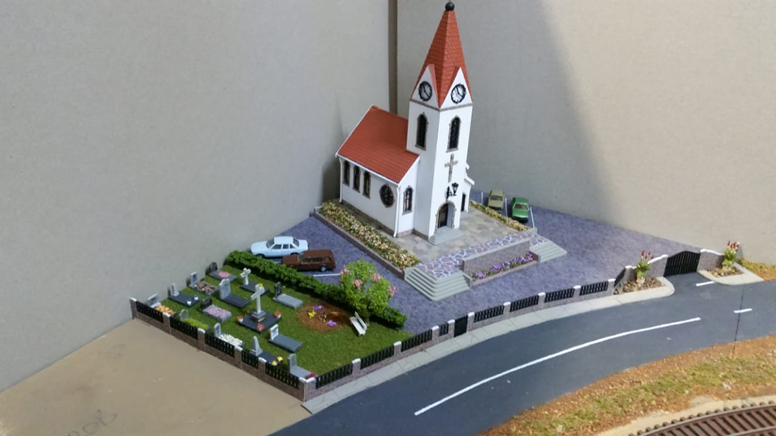
Now on to Heinrich (You can see his last post here).
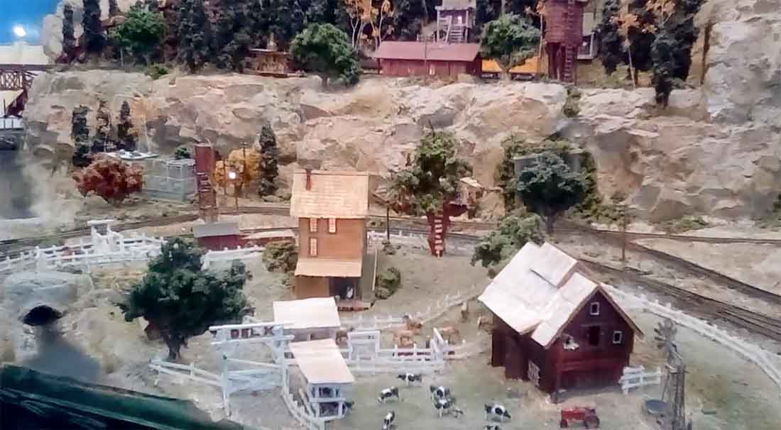
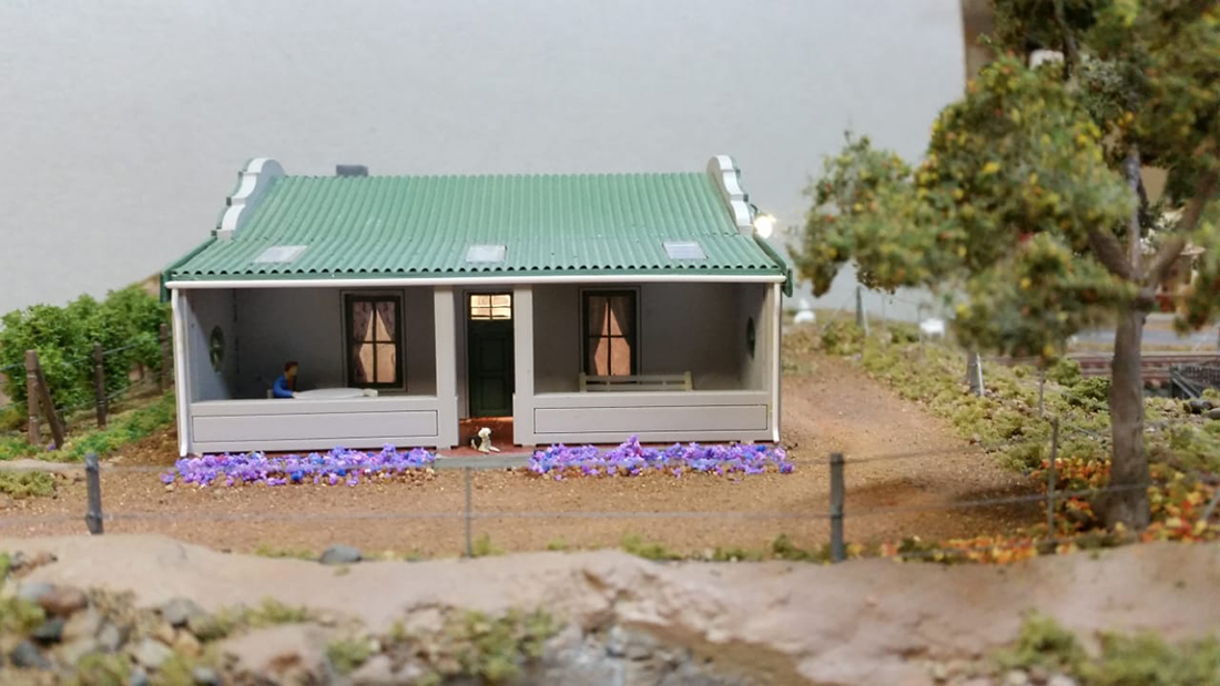
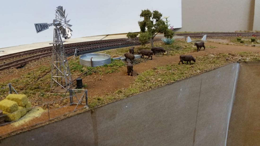
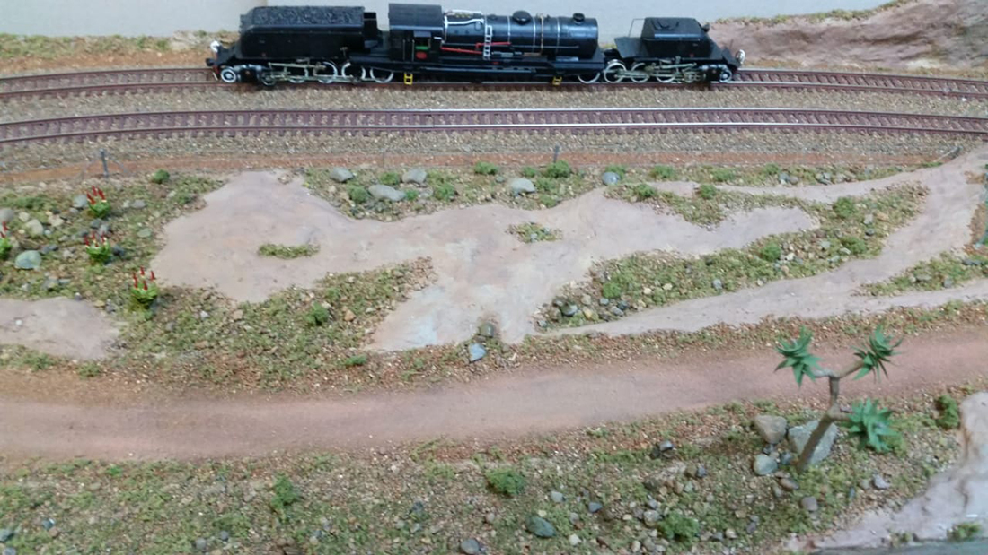
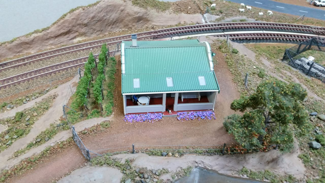
“Good morning from South Africa again!
Al, I would like to share the latest developments to my Karoo themed layout. A lot of credit must go to Johan, the builder of my layout.
Regards,
Heinrich”
A big thanks to Heinrich and to Paul for sharing his N scale hotel scene.
That’s all for today folks, please do keep ’em coming.
And if today is the day you take that first step towards your own layout, the the Beginner’s Guide is here.
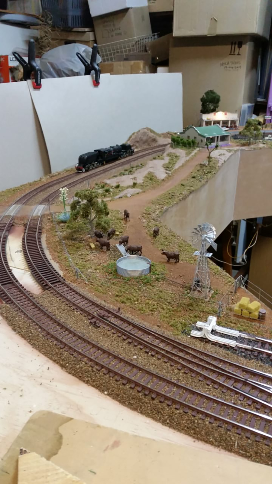
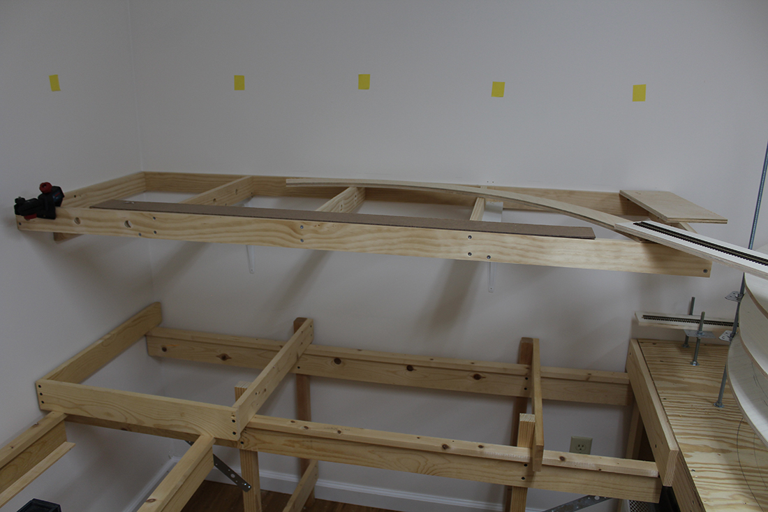
Have never emailed you before but am slowing working on my double deck HO layout now that I am supposedly retired.
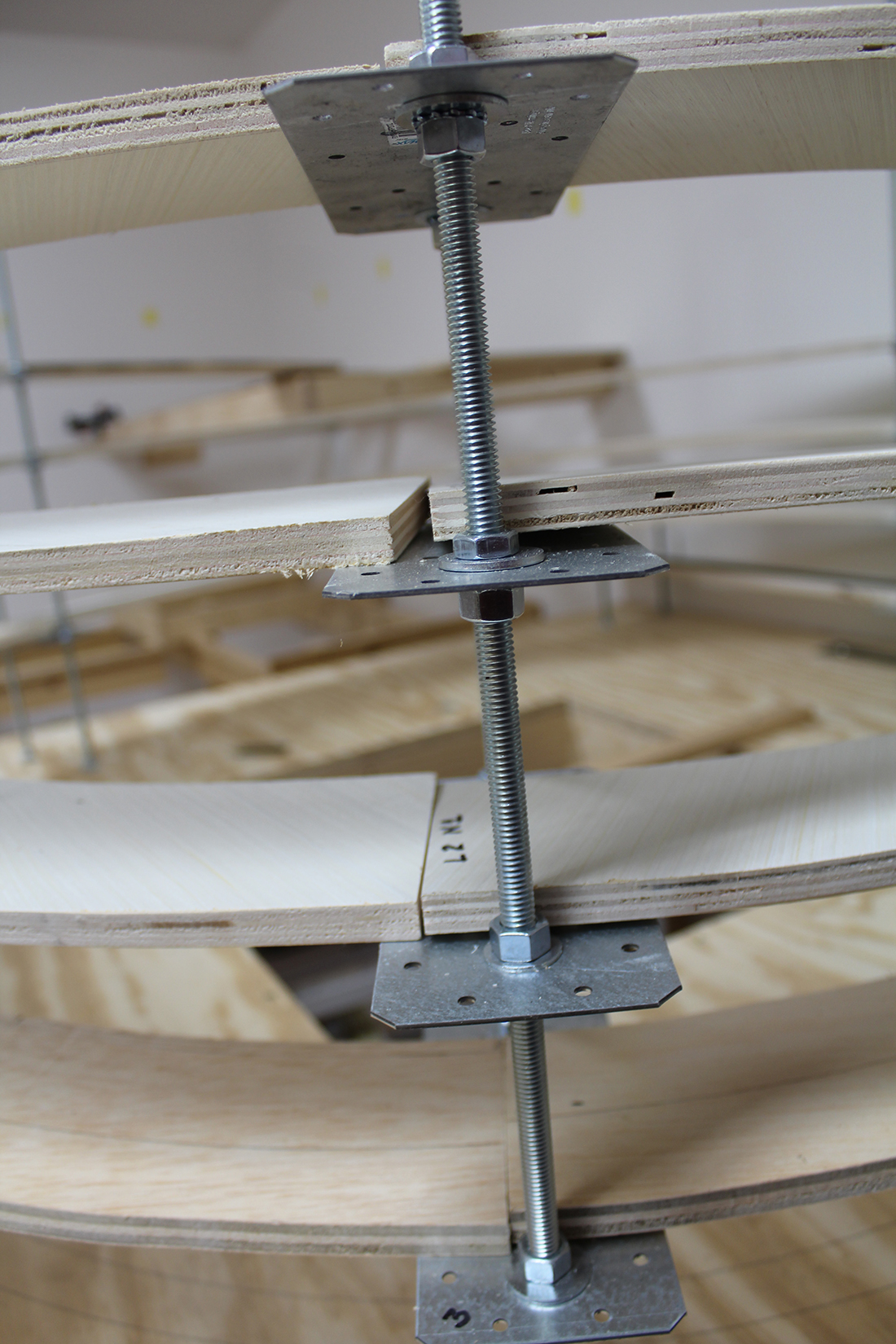
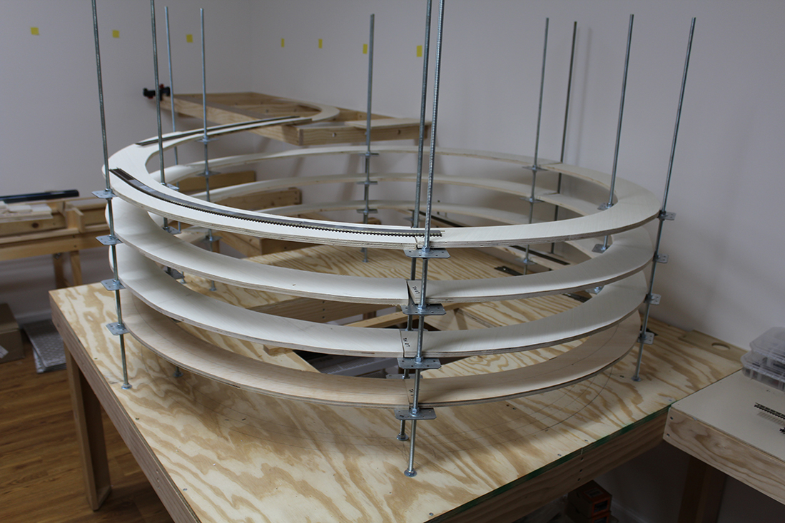
It’s an approximately 10’ x 18’ space in my basement. The levels are about 16” apart from top of level 1 to bottom of level 2, but the helix needs to go up to 19” to get to the top of level 2.
The model train helix is a 26” radius curve (as big as I could go) resulting in a 2% grade, which should be very manageable for my locomotives.
The supporting structure, as you can see, is threaded 3/8” rod with home store tie plates acting as the shelf for the end of the curves. They already have numerous holes drilled in them so I will use those to bolt the plywood roadbed to the plates.
Everything seems to be very stable so far, but have yet to run any trains. Each curve covers 120 degrees, so there are three pieces of ½” sanded plywood curves per level.
The construction allows me to automatically super-elevate the continuous spiral by simply raising the outside nuts a bit over the height of the inside nuts, nothing will have to be done to the track work itself. I read if you were going multi-level you needed to build the helix first, so that’s what I did.
I am modeling the Missouri Pacific De Soto subdivision during the late 60’s and early 70’s from Riverside to Cadet, MO and the extension to the Pea Ridge iron mine. I grew up in De Soto, the home of Missouri Pacific’s car repair shops.
I am still finalizing the track plan. Current idea is to start in Riverside on level 1 go through Horine (interchange with Frisco) then up the helix to De Soto.
Once I get all that done, I hope to go to layer three to get to Pea Ridge.
The De Soto subdivision run’s from St. Louis, MO to Poplar Bluff, MO as part of the Arkansas division – St. Louis to Little Rock. II will be using NCE DCC.
I hope you enjoy my model train helix and I am happy to answer any questions.
Gary
Hillsboro, MO USA”
“Alastair,
I commented on the recent blog entry regarding coal loads.
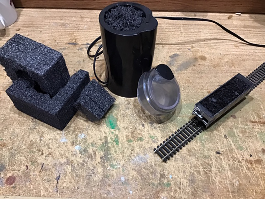
My neighbor was throwing out black styrofoam packed around furniture legs, which I grabbed. I then bought a used coffee grinder from our local thrift store. K-Cups have made these almost obsolete.
After filling the hopper, I spayed the top with hairspray. I can easily pull a long train of filled hoppers with a single Diesel engine.
Love your Blog
Marvin”
Now on to Jim – who has been kind enough to answer some questions on his last post, which is here.
“Hello Alastair
Several of the people who responded to my latest work on Starrpoint, had some questions regarding several areas, NCE SWITCH8 MK2, the BI-COLOUR LED work and my transfer table.
First lets touch on the NCE SWITCH8 MK2. GEORGE ZAKY wanted some information on what goes into installing one. So for George here is my reply:
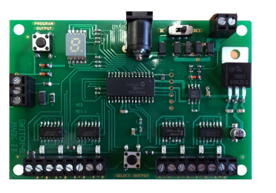
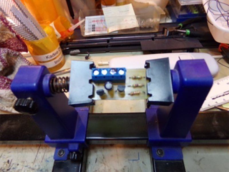
Here is a picture of the NCE SWITCH8 MK2 board
When you look at the board, you will notice several terminal blocks on the board. The one at the upper right is for power. This is where you place the power wires either from the track, or from a separate power source.
To the immediate left of the power terminals is the selector switch for DC or DCC operation, which ever you are using.
To the extreme left of the board is a terminal board with three screws. These are only used if you plan on using toggles to throw the turnouts as well as the automatic system. I never use these since I only use the automatic system for the turnouts.
On the bottom of the board there are 2 banks of 8 terminals. It is here were you wire the turnouts. They are numbered 1 a b, 2 a b and so on until you get to the end of 8. You need two wires from the turnout, one for closed and one for thrown. The best way to wire the turnouts for proper alignment is to look at the turnout you are going to wire.
Now for tortouise switch machines, you only use terminals 1 and 8. So take a wire from terminal one of the tortouise and connect to terminal 1 a, take a second wire connect that to terminal 8 at the tortouise and connect that to terminal 1 b and then at the NCE SWITCH8 MK2 board. You now have one turnout wired. The rest follow the same wiring pattern.
Now you will notice two buttons on the board as well. The one on the bottom centre of the board allows you to toggle between the wiring points. A LED will light indicating the terminal selected. You will also notice that in the upper window a number will appear indicating the terminal is selected.
Now for the fun part of all this, you can program all of the turnouts with individual numbers. To do this first push the center button on the bottom and select the turnout you want to program.
Next push the button on the upper left corner, this is the programming button. You will notice that a flashing “P” will appear, indicating you are ready to program the selected turnout. You will need your DCC throttle to program the turnout. You can use any number you wish up to 3 numbers only. Push SWITCH on your throttle, select the numbers you wish to use for that turnout, and you will notice on the throttle either a “T” of “C” appear on the throttle screen. Simply choose the opposite alignment and you have now completed your first turnout programming. Congratulations.
ROLAND ALDRIDGE commented on using the BI-COLOUR LED’s for the turnouts. I did use them for all of the switches, however the way you mentioned and noted on the instructions from Tortouise I had issues so the way to solve the problems was to first wire all of the turnouts with the power wire on a continuous loop. All eighteen turnouts were wired in series, with only one wire to the main panel and connected to a DC power source. This eliminated the voltage drop at the turnout power. Next RED and GREEN wires from the tourtouise were brought back to the main panel and connected to the individual BI-COLOUR LED’s. You are right there was a lot of wiring doing it this way, but found it beneficial. No issues with the turnouts.
MARKUS MUETSCHARD wanted information regarding the WALTHERS TRANSFER TABLE.
Well let me tell you, I was devastated the day the transfer table stop working. I found the issue to be with the electronic board that controls everything on it. I contacted WALTHERS, and HELJAN ( who originally made the transfer table for Walthers ) to purchase a new board. None are available. So now what needs to be done? I did not want to remove the table and have to fill in the space with wood. And I could not use a turntable to utilize the buildings in the Diesel area. I had to find a way to make it work. So I put on my electronic thinking cap, and came up with a solution. A DC power pack could be used to control the movement of the transfer table deck. So that solved that problem. But what about the lighting? AH there was the ultimate headache. There are two lights for the table and one that blinks indicating the table is moving.
So what to do? Well there was only one solution, design a electronic board to control the lights. Here is a picture of the board that I designed and built to handle the light issues
The board contains two transistors, one NPN and one PNP. Three resistors are necessary, 1K, 100 meg and a 47 ohm. A 2.2 ohm capacitator, and a four terminal wire connector.
And it works. Now I can use the Transfer Table again with added excitement.
I hope the information and answers to all of the above questions are helpful.
Jim Sr
Starrpoint RR”
A big thanks to Gary for sharing his model train helix, and to Marvin and Jim.
When it comes to a model train helix, I’m always reminded of Lawtrences helix.
That’s all for today. Please do keep ’em coming.
And don’t forget the Beginner’s Guide is here if you want to take your first step with your own layout.
The talented Bill has been back in touch, with his N scale model train scenery.
You all know how much I like an update – and Bill never disappoints.
(His last post is here if you want to get up to speed.)
“Good Day to you Al,
Every morning I continue to check my personal email first thing to see the great posts submitted by fellow modelers that you share with us.
I have not missed a single day since discovering your site now almost three years back.
I took some vacation recently and I spent a good portion of the time in the garage.
Most time has been spent on the N Scale layout doing more scenery including adding in roads and details.
One quick tip to share is to use craft pins for posts in N Scale. I cut the tops off and leave about a one inch long pin.
About half of that I’ll paint white or rust with enamel paint.
Let it dry overnight then use a slightly thicker pin to crest a pilot hole to insert the painted pin. They are perfect for use in n scale.
I also spent time working on my HO Scale switching layout and finally finished the fuel depot and got rid of the pink foam board from that area of the layout.
I’ve attached a couple of photos. One shows the fuel depot now and the other my n scale.
I’ve also attached a video showing the new scale and scenery and road construction and the other work on the HO scale layout.
I’ve not been traveling for work so I’ve had plenty of time to spend working on the trains after work and on the weekends.
Cheers and be safe!
Bill in Virginia”
And now onto Geoff:
“Hi Al,
Here are inexpensive resources I like to use.
I am near Toronto, and model North American Railways. So I am passing on a few tips I have used for N Scale model train scenery.
One cheap and cheerful resource for ballasting, that is better kitty litter, is using Brita Water Filters for ballast. When the filter is finished its cycle, allow to dry for a few days to let the water drain out. The contents are a black and a greyish white colour, and is very fine and ideal for N Scale in its many appelations.
The second is my choice of paint for buildings, freight cars, and painting the track. I like to use ‘plastic compatible’ brown coloured automotive primer paint. When applied, it looks awful, then dries very thin. On buildings it will hold water based craft paints, and a water-ink wash for weathering buldings.
N scale track is so disproportionally tall, that I am in the habit and practice of paining track. My choice is to ballast first, and then paint the track. To paint track, let dry and clean the top with a left over piece of cork roadbedding. It wipes off easily, and if in the switch/point blades is cleaned with a Q-tip. A black water-ink wash then makes the whole thing appear more interesting, once scenery is applied the appearance is interesting. I can send photos of examples if need be.
A third tip is using WAHL hairclipper oil applied to the top of the tracks for sustained and clear electrical contact. Use a left over piece of cork to clean…
Like any new technique, experiment on scrap first.
Hope these are helpful
Regards
Geoffrey”
“Al,
as a follow-up to spray painting the ties brown, IF you take a drinking straw and using a sharp knife,
slice the straw length wise (put a slit in the straw) this will slide over the rail and give some protection while spraying the ties.
Cheers,
Glenn”
“Hi Al.
I see a few people are interested in telephone or power poles.
Maybe i can lend a hand on showing how and sort of kit you need. Really simple to do once you cut and set up, most slow and tedius work is the tiny pins you use on the cross members to hold the tiny insulators.
Start with a quarter diameter dowel you find in hardware stores.i cut mine 6 inches because i put 1 inch in my styrofoam base.on the dowel measure from one end, half inch and drill a tiny hole careful.
Take a popsicle stick and cut it into 3 lenght wise strips. Take the best cut piece and measure 2 inches in lenght and cut.
Now find the centre and careful drill a hole. Your going to notch the pole you drilled to fit that cross beam.
Now take a black or white plastic with a metal core electricle twist tie and strip it. Those are going to be cut long anough to carefuly pin it to the side of that popsicle stick in picture instant glue them on. Leave a space but barely when you add the 3 insulators on each pin, they come in diffrent colors.
Where you drilled the post the first time move down to the desired spot you want to plant your scrap radio compasitor acting as a trasformer.leave the pins on the compasitor when cut out of radio.look in radio for a cooper wound resister as seen in picture.now move down to desired spot for transformer and mark spot.
Now take some more thin metal scrap from radio and cut a tiny metal bracket on post. Sorry for picture. That metal bracket will hold your transformer.instant glue trasnformer to braket and instant glue bracket to notch post.the metal silver wire you see in photo is thin flexable weilding wire to make tiny fuse brakckets you see in other photo.
To make fuse take sewing needle carefuly wind cooper wire you salvaged to tiny coiles as seen in photo.you will have to trim them as you go.you will see in photo a piece of food tin.cut into tiny tiny strips and use a finger to even out.those will act as cross beam member supports and also bracket for fuse as seen in photo.after happy with how it is install cross beam with insulators in top notched post and use a sewing pin as a bolt and white glue it. Trim extra after dry.
Diffrent countries have diffrent designed post and telephone poles. If you look on the net you can get many photos of power poles and telephone poles.mine are canadian poles and are close to being correct.
Now in canada we have our maine power wires and telephone wires and cable high speed hanging attached a few feet from the bottom of our transformers.the insulators hold our ground wires.but in my case im going to use my poles to hook up real power at low voltage for home lights and street lights.the trasnformers are for the look or realisume.hope this helps and if any
questions leave a message on the site and i will answer.
Have fun.
Kim”
A huge thanks to Bill for sharing his pics and videos on his N scale model train scenery – can’t wait to see the next update too.