Bob’s been in touch with a useful ‘how to’: How to connect led strip lights to power supply.
“Hi Al,
I love your site and I can’t wait to read the latest installment each morning.
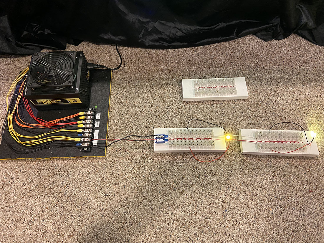
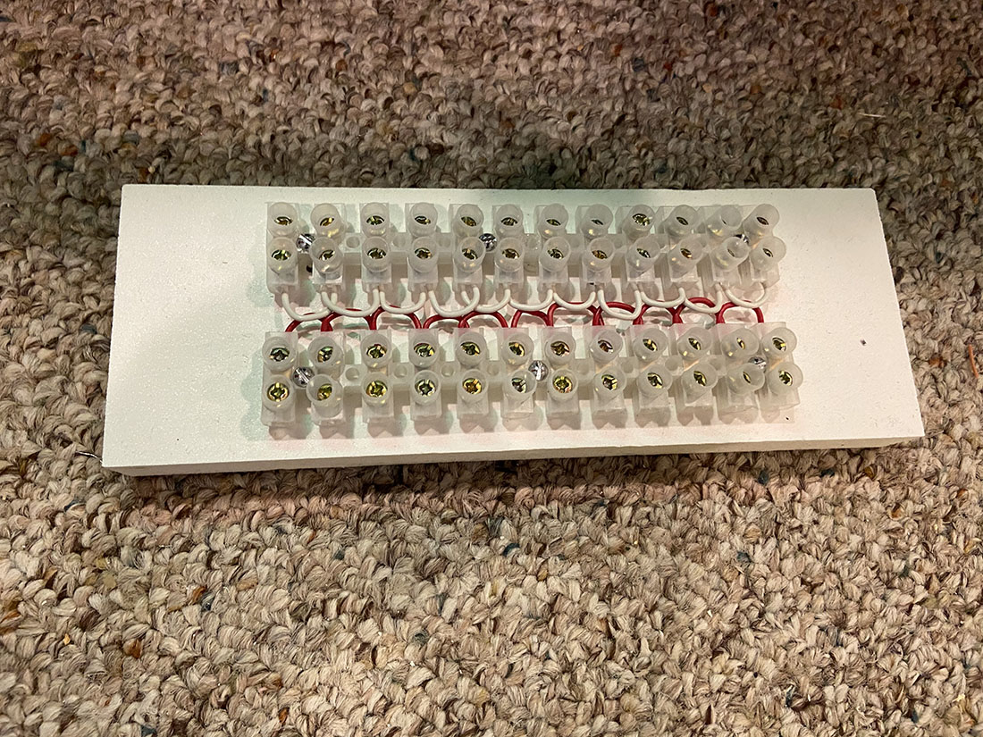
I have learned a lot from your blog so I thought that I would contribute a little with this power supply and hookup units “manifolds” as I like to call them , that I made.
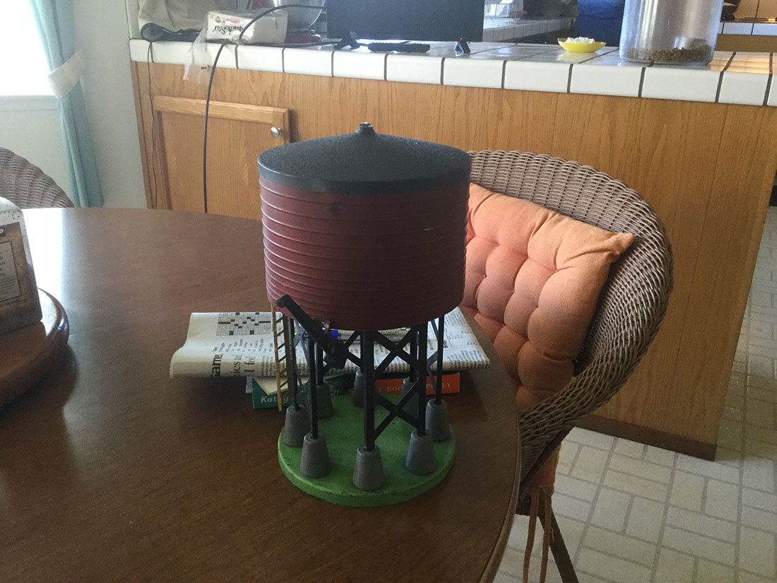
Under my layout are 8 of these “manifolds” shown in the first picture.
They are daisy chained together to form an expanded hook up for my lighting.
They are hooked up to a computer power supply that I converted to light my layout.
The supply has 12volt,5volt and 3.3volt supplies perfect for supplying whatever voltage is needed to light the entire layout!
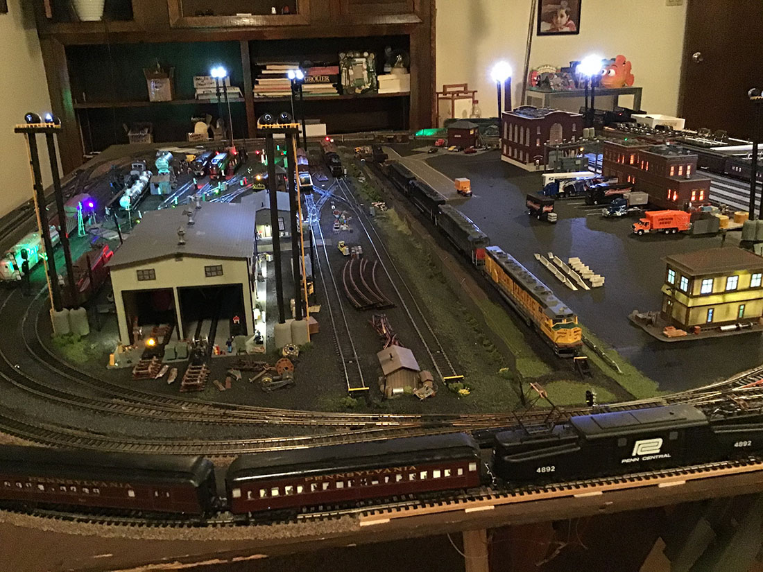
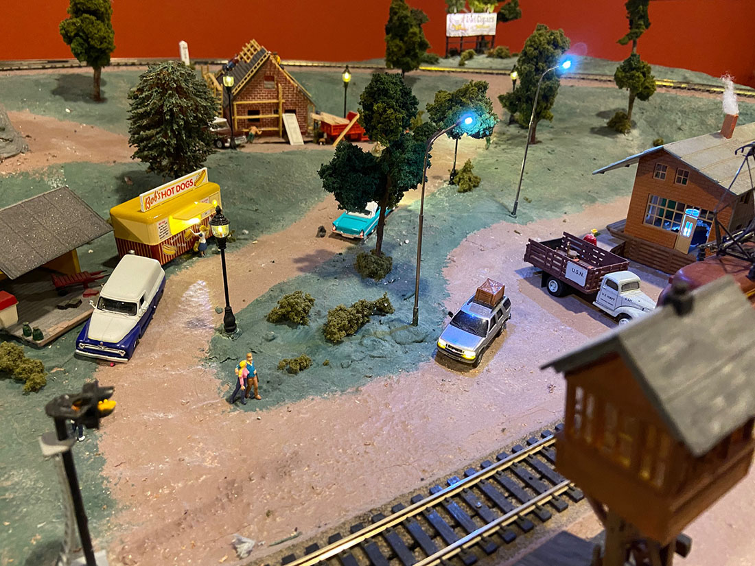
All of my lighting is Led from the buildings to the street lights and the vehicle lights.
Hope you enjoy these pictures and hints ,maybe some of your readers will learn something as I have done from this site!!
Thank you for all of your hard work to keep this site going strong!!
Bob ( From Pennsylvania)”
Now on to Martin.
He makes no bones at all about being a modeler that likes to ‘make things work’ rather than getting lost in the scenery.
I know there are many of you just like Martin too.
And that’s fine – the wonderful thing about this hobby is you can just enjoy the parts you like.
Talking of which, wait to you see how Martin gets his stock off the layout so he can clean the track. It’s all in the vid!
“Al,
First of all, thank you for hosting this site.
I have thoroughly enjoyed seeing what everyone else is doing, but have been reluctant to show mine until now.
Like many others, I had a train set in my school days, which expanded haphazardly in the loft. This had to go when the slot car racing bug bit me in the 60’s.
Now I am retired, and after a few years of negotiation with domestic management, gained agreement to take over our spare bedroom / study and evict the bed.
I have been working on & off for a couple of years on the layout, progress has been slow because I have a number of other interests but the lockdown has given me the opportunity to catch up a bit.
I have made plenty of mistakes along the way, possibly the biggest one being leaving it far too long before getting your beginners guide!
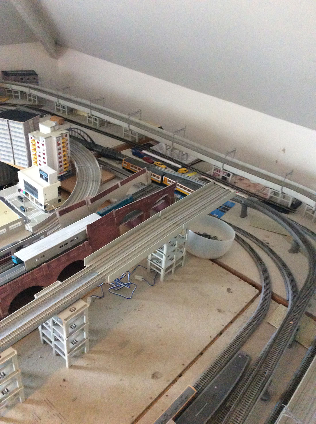
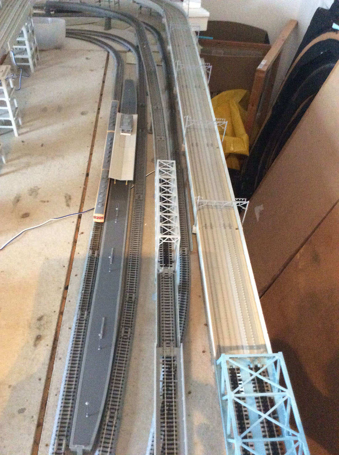
So far, I have concentrated on getting a working layout so no scenery evident yet other than a section of ballasting but I thought you may be interested in the features I have managed to incorporate so far.
I should add that I was a bit ambitious in that my 8ft by 7ft layout incorporates 30 points and 2 double slips – maybe that is why I have spent so long getting things to run smoothly.
I am one of those modellers who gets most pleasure from making things work rather than the scenic aspect of the hobby.
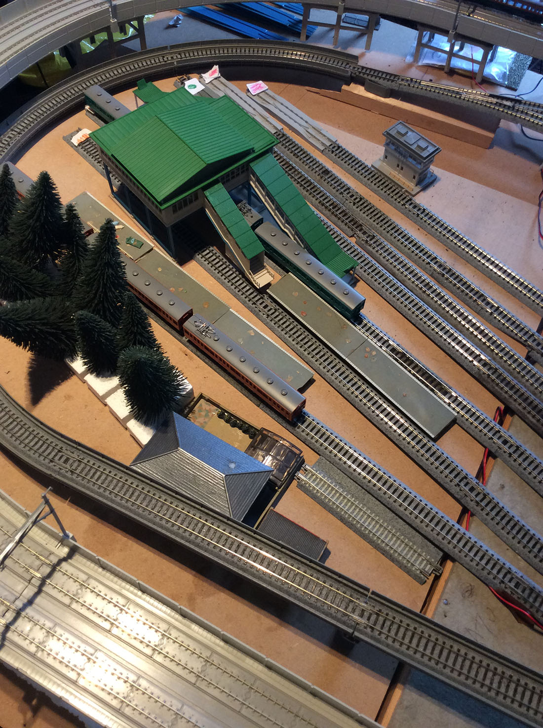
Hopefully, when developed further, the layout will be a representation of the East Kent area, where I grew up going to school by train and later to work.
Although intended to be set in the late 1950 – early 1960 period, I also intend to include a Colonel Stephens line, assuming it stayed open into this era.
The baseboard is constructed in sections, the largest being 4ft X 2ft, made of 9mm ply on a 3X1 frame.
The sections are located with brass dowels and held together by 8mm coach bolts, sitting on, but not fixed to a 2X2 framework located on notches in the base board frames.
This allows any section to be removed without having to dismantle the whole layout.
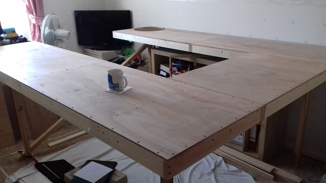
Since this photo, I have added 2 extra legs and replaced 2 legs with old desk pedestals.
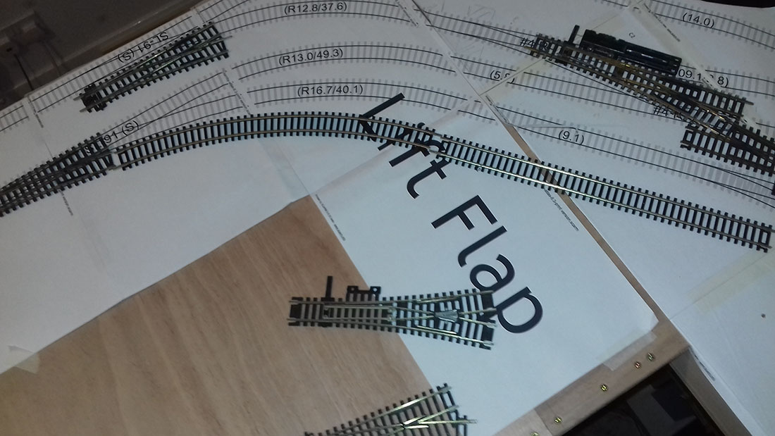
I started by using SCARM to develop the track plan and printed it full size which proved extremely accurate and made track laying relatively easy, although I did deviate from the plan in a number of places as I went on.
I have soldered dropper wires to every piece of track, to avoid relying on rail joiners for an electrical contact, and run these to the inner edge of the baseboard where the bus circuits are contained in trunking.
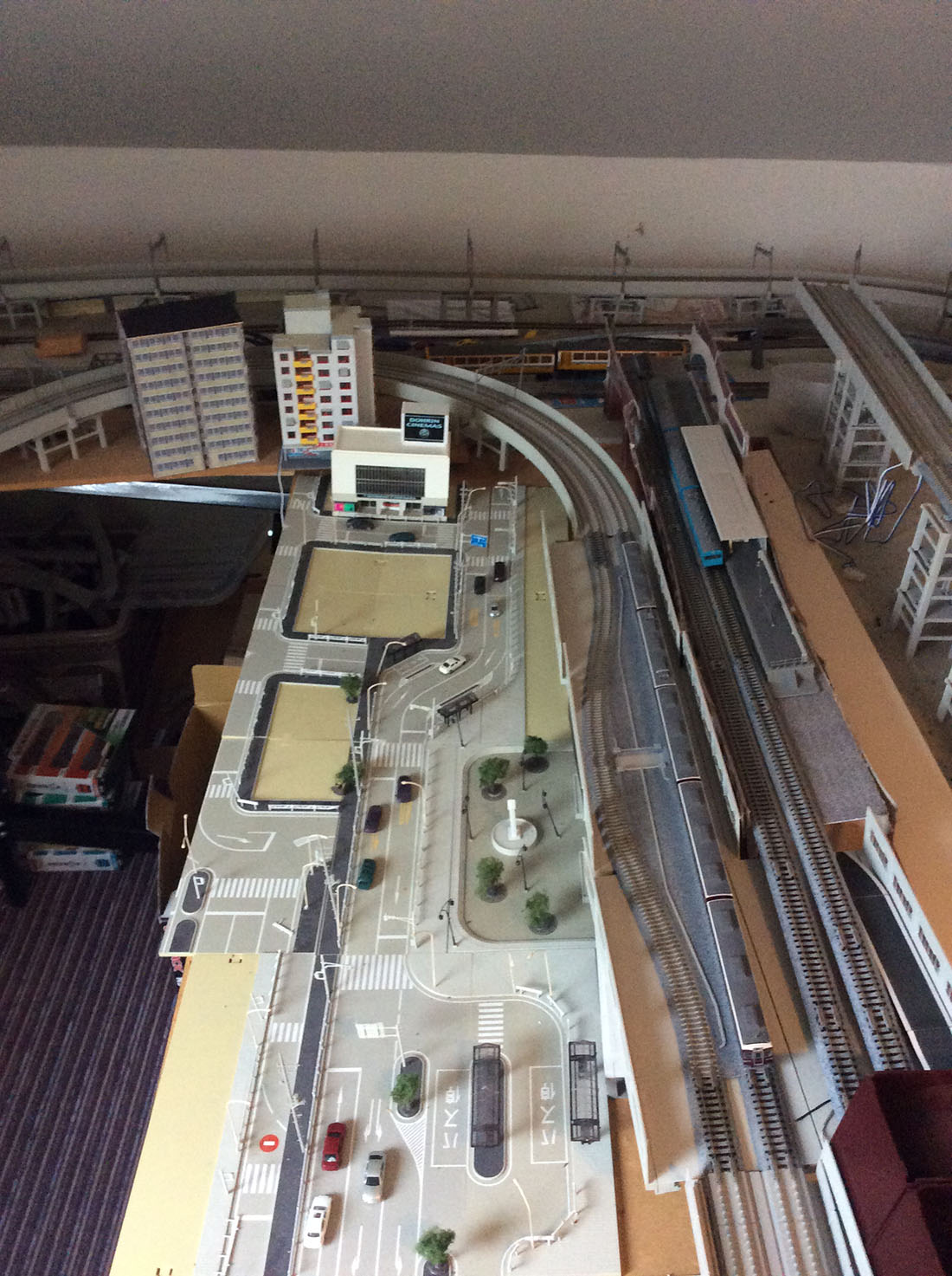
The layout gives point to point operation on 2 branch lines, and a double oval for continuous running as well as a small goods yard for operational interest.
The innermost loop is electrically isolated from the rest of the layout and connected as the DCC programming track, as well as being switchable to an analogue controller to allow me to test run a DC loco.3
I have used Peco code 100 track and points throughout, all operated by servos and controlled either from a mimic panel or by DCC from the main controller.
This is accomplished using equipment from Megapoints Controllers, which has so far proved easy to use and very reliable as well as being more cost effective than using solenoid point motors and DCC modules.
As a bonus, the customer service from Megapoints is second to none.
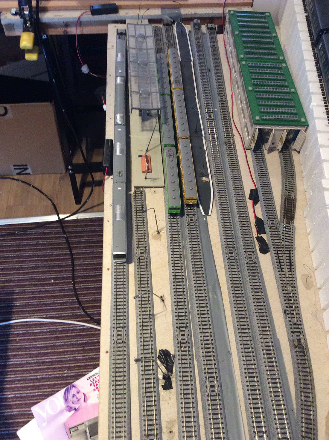
Although I thought I had allowed enough storage tracks for all my stock, I have already found that trying to clean the track with a layout full of stock is a nightmare, so I have made up a storage solution which I think may be of interest.
This allows me to clear the track and put everything out of harm’s way without handling the stock, and double as a fiddle yard.
I have made a short video to illustrate this, which I have sent as an attachment – I hope this is OK.
Regards
Martin.”
A big thanks to Bob for sharing his ‘How to connect led strip lights to power supply’ step by step. And thanks to Martin too.
That’s all for this time, folks.
Please do keep ’em coming.
And don’t forget the Beginner’s Guide is here if you want to join in with the fun.
Best
Al
PS Latest ebay cheat sheet is here