Gary has been in touch with an electrical power problem with his layout – could it be the MRC railpower 1370 overheating?
Have a look at the comments below and make your own mind up.
If you’re unfamiliar with his layout, his last few posts are here and here.
If there’s one thing I have learned over the years of doing this blog, is that all layouts present a whopper of a problem at some point.
But they are nothing a bit of thought and shared experience can’t overcome.
So let’s see what we can do to help Gary.
“Hi Alastair:
I need some help and guidance from you and/or your many railroad modeler followers.
I have a major electrical problem. I have been using a MRC railpower 1370 to provide AC power for building lights, Atlas switches and LEDs for the signals on my layout.
I have 33 switches, 55 LEDs for my dwarf signals and 13 LEDs in my buildings for lighting.
All my track power is DC from a separate MRC railpower 1370 transformer.
For my Atlas switches, I am also using Peco DL-35 C.D.U.s (Capacitor Discharge Unit) for additional initial power to throw the turnouts.
Electrically, everything has been working ok for over a year that I finished the engine yard. The switches in the passenger yard have been working for close to two years. All off the one transformer which I only use for AC.
I have 3 DC buses from a Railpower 1300 and 3 AC buses from the MRC railpower 1370 that run under the layout providing power. The wires from the transformers go to distribution blocks which then I turn goes to the different accessories.
This past Friday as I was trying to make a video of the layout that some of the modelers ask for from my last post. The layout was on for about 20 minutes and then all my lights dimmed and went out and switch power was lost.
I switched the power button on the AC Railpower 1370 transformer on and off a few times and nothing worked. I waited a few minutes and turned the power back on and everything worked and lit up and then dimmed and went off after about two or three minutes.
I have found out that the longer I leave the power off, when I turn it back on, the longer it stays on but never last more than 20-25 minutes.
It does not act like a short where it goes right off; it works ok, and then dims out.
I am not sure if it is an overload because it has been working fine for a long time.
Yesterday, I added an additional New MRC railpower 1370 and started moving the AC buses off the first 1370; same problem until I move ONLY AC bus 1 to the new transformer and the problem happened with the new transformer with only the first AC bus which has most of the accessories on it.
I still don’t know if it’s an overload or a short.
Has anyone ever run across this?
I am going to call the manufacturer, MRC (Model Rectifier Corp.), here in New Jersey, U.S.A., tomorrow morning and see if I can speak to one of their technical people.
I have so much wiring under the table, I don’t know where to start. Everything has come to a halt with this issue. I dread having to go under the layout and follow every wire.
I know this is not going to be easy.
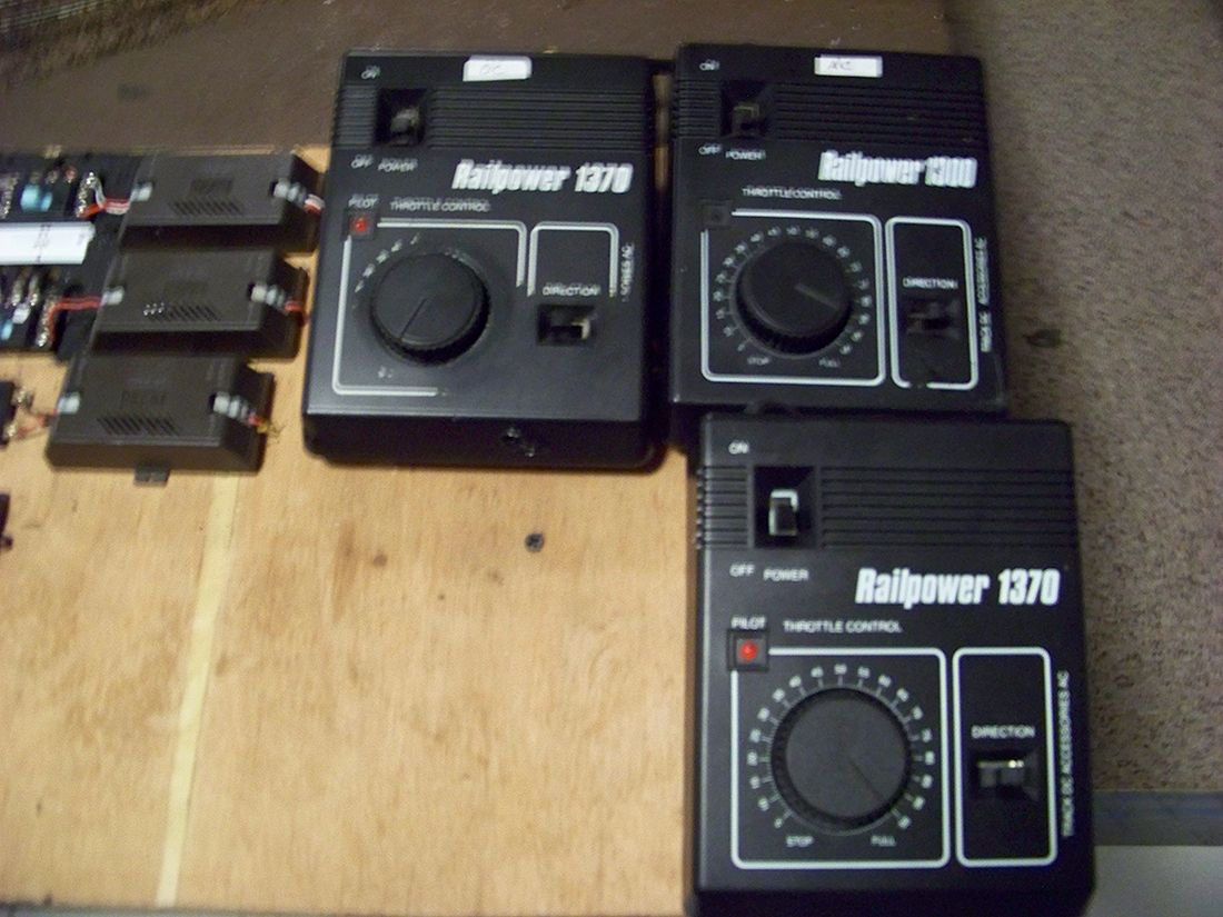
Here are the power packs. The 1300 is the one I am having the problem with.
I hope someone can help with some knowledge or experience about this.
Gary M from Long Island”
A real head scratcher – could it be the MRC railpower 1370? Or a short? Please do leave a comment below if you can help Gary.
Now on to Tony:
“Hi Al,
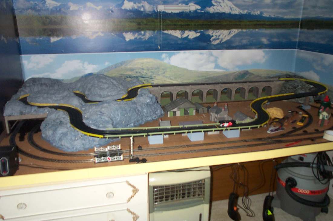
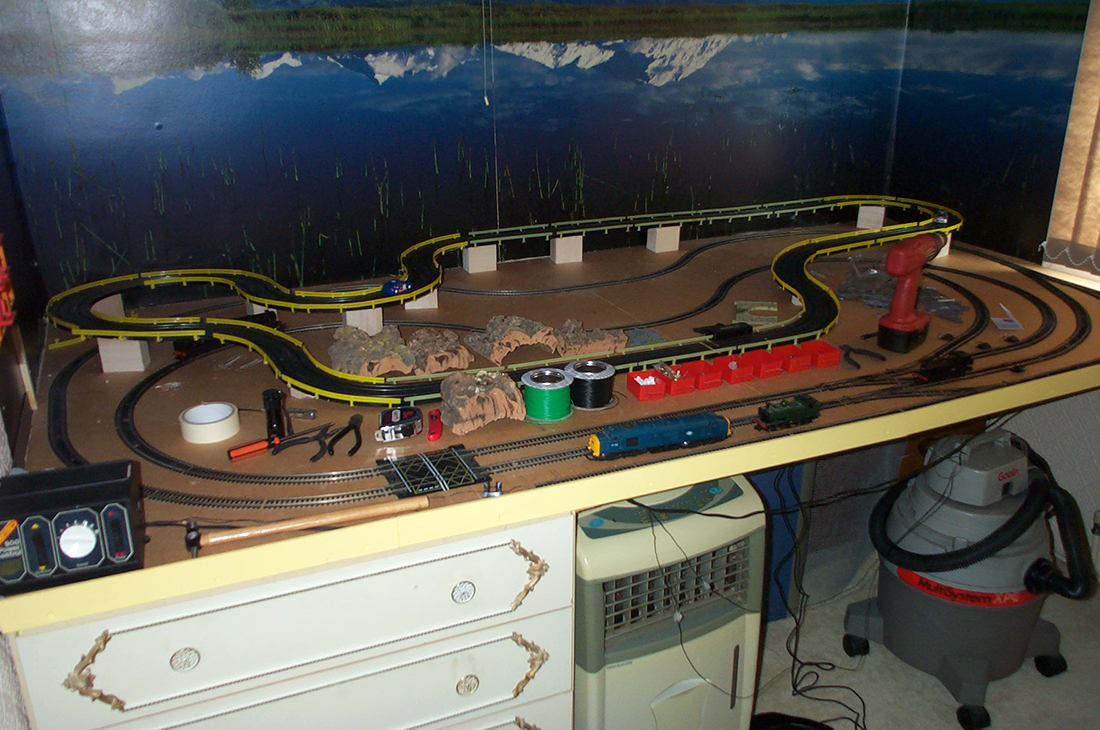
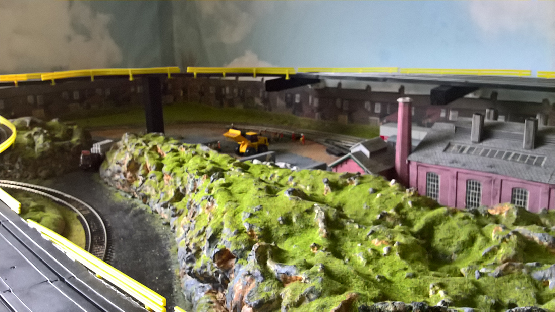
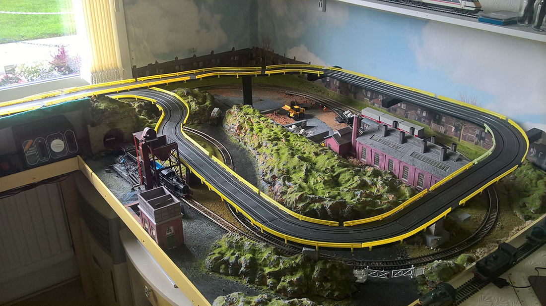
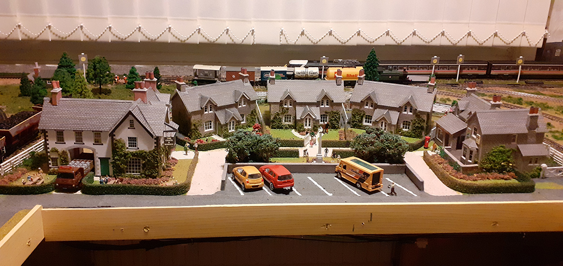
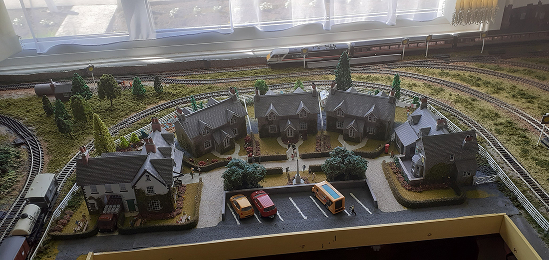
Thanks for posting pictures of my combined layout of both 00 gauge railway and micro scalextrix.
I have moved on since those early days to a “finished lay out” as of today.
I am happy for you to share these photos and welcome any comments members may wish to make.
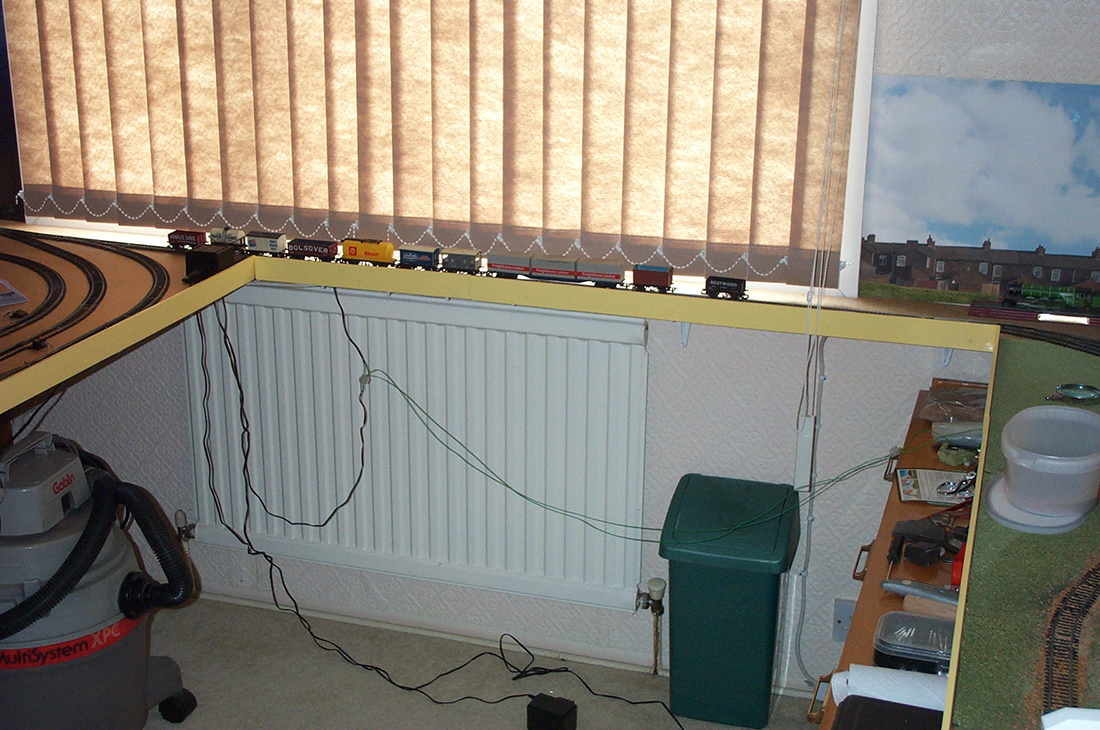
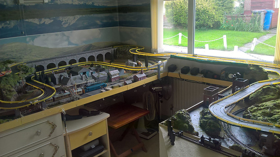
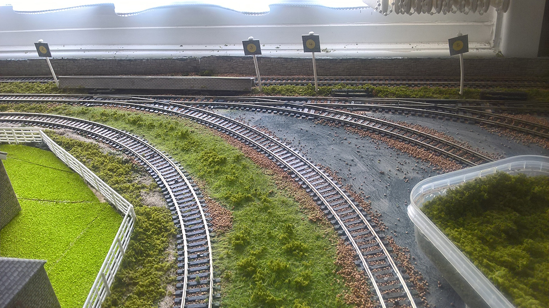
I modified the first layout by extending the area in front of the window to first situate my controllers and extended the area to the right so that I can have a return loop back to the main board and extend the micro scalextrix.
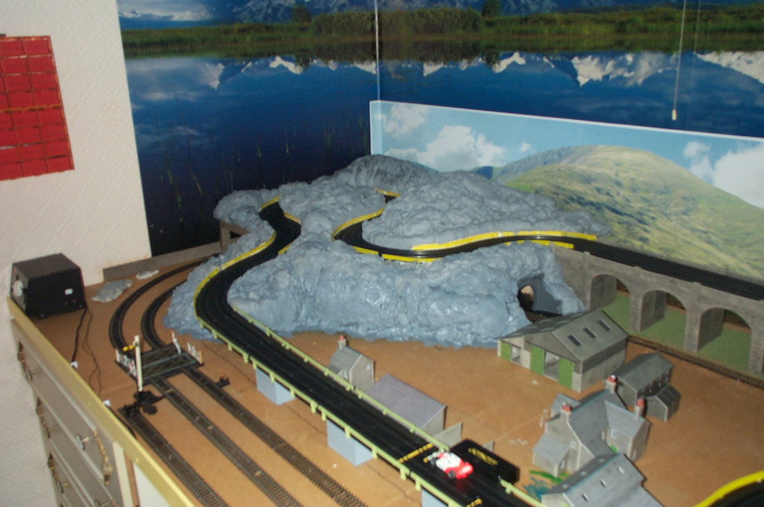
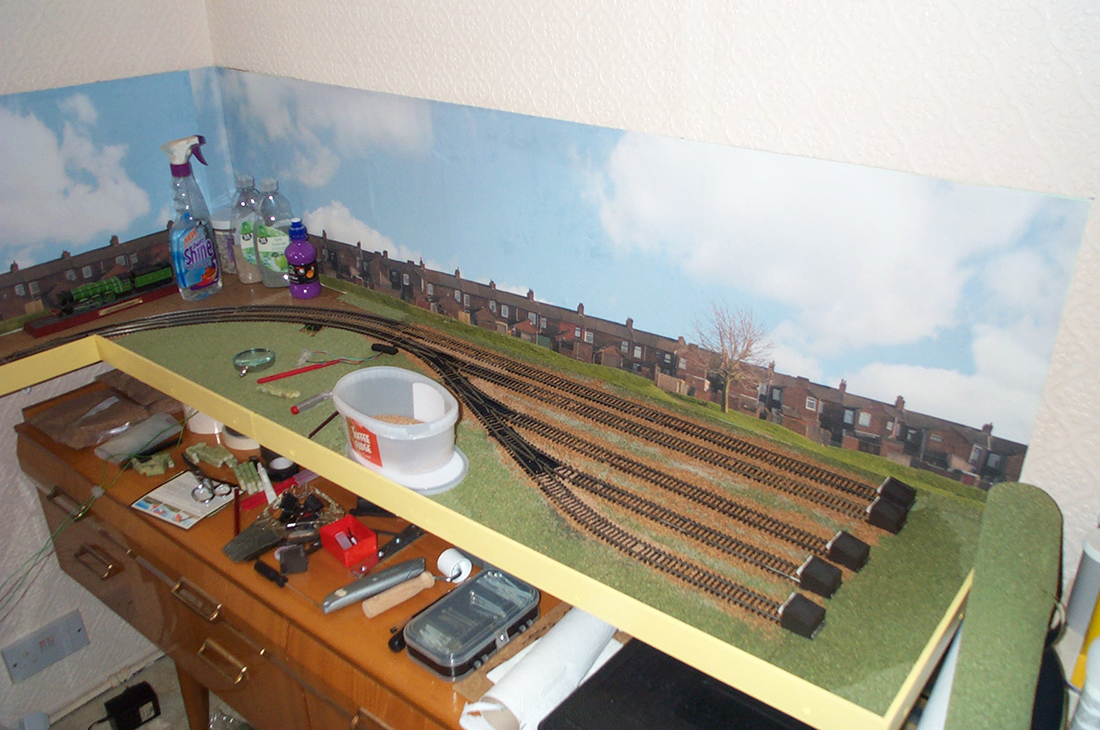
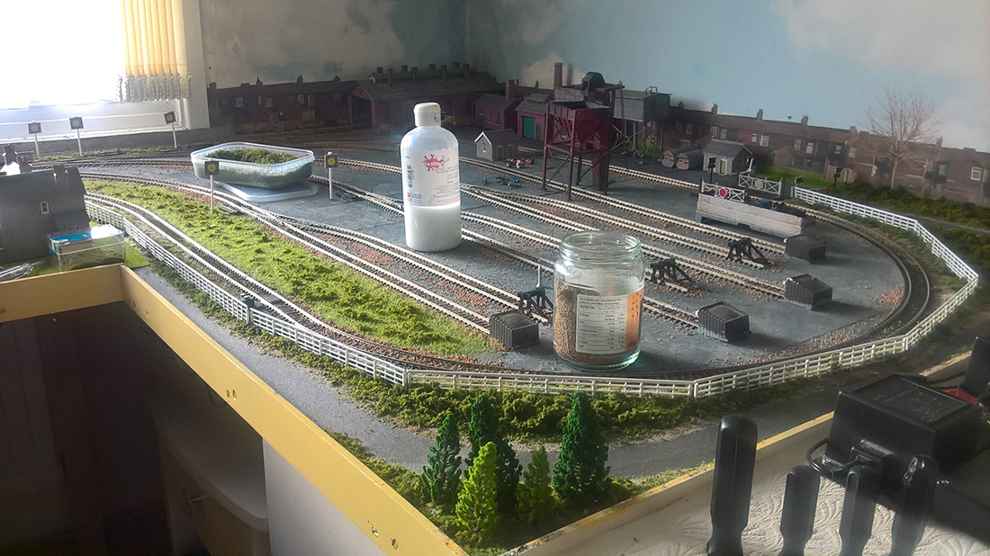
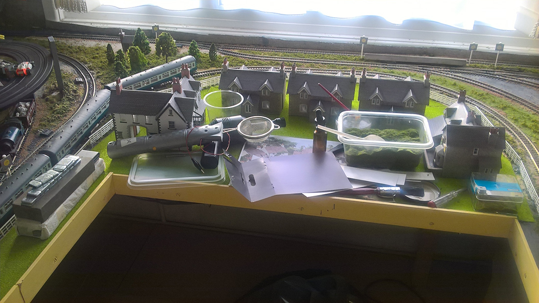
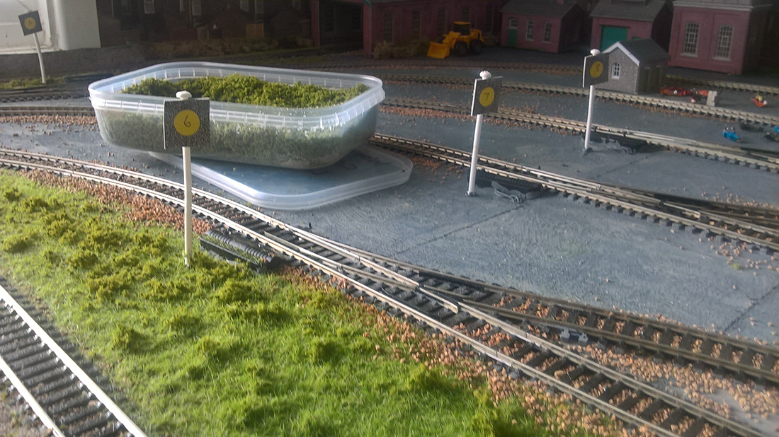
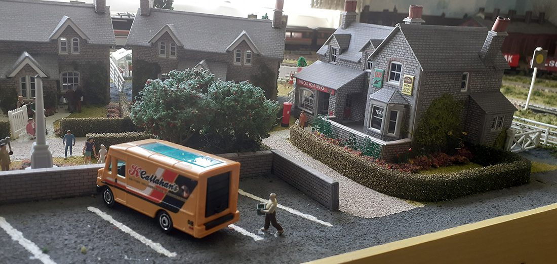
After a few months I decided to change again and further extended the window area to situate a village scene and completely changed the right hand side to place sidings for all my other locos etc.
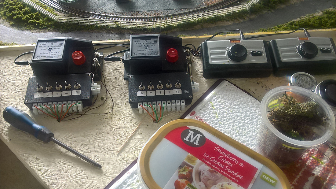
This now was the first time I attempted to use point motors and after a couple of trial runs – see photos, I managed to set up a neat control panel of switches next to the power units.

Keep up the fantastic work which we all very much appreciate.
Tony
Stockport
Cheshire”
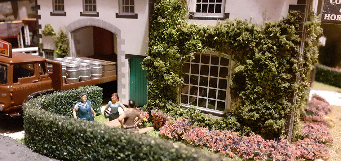
A big thanks to Tony. I remembered his original layout – hard to forget a layout with a race track! Wonderful stuff.
That’s all for today, folks – except please don’t forget Gary ans the thorny issue of his MRC railpower 1370. Can anyone help?
Please do keep ’em coming.
And if today is the day you make your start, just like Gary and Tony did, the the Beginner’s Guide is here.
Best
Al
PS Latest ebay cheat sheet is here.


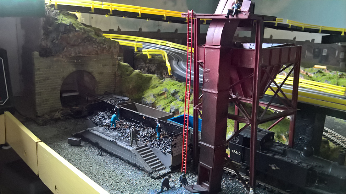
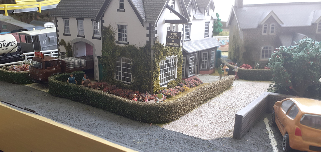
Tony….. great layout……I love the detail with the ivy on the front of the house and the coal storage scene is really good. Question for you; in the 6 picture from the end you show two what look like power packs with toggles? What are they?
Great work
If it happens at the same time every time I would look at the transformer. Could it be a safety cutoff in the transformer to protect the unit. Once it reaches a time on, then the safety feature kicks in. Again, the timing is what is interesting in this matter.
Hi Gary
Have you tried your lighting with a ‘DEAD’ track?
Could be some interferrence from the track power, could be poor insulation
between power supplies?
HI Gary
Is it an overheating problem with either the control box, a capacitor or the power pack? Overheating sometimes results in a slow shutdown as opposed to what we normally see with shorts causing an instant shutdown. Overload would seem a more logical problem that a short.
Does the shutdown occur if no trains are running ie: just lights on? If you have a loose connection somewhere a train passing might trip it through vibration temporarily. Never seen this before so good luck!
For Gary…..I do not envy your dilemma and from what I understand, your only choice is going to be to follow the wires. I am assuming that the problem is either a damaged wire or a faulty device. From your description, it would appear that you have a device that is getting hot and causing the built in overload protection in the transformer to kick in and cut power to the output. The first thing that I would do is, as soon as power is switched on, go under the layout and see if any of the wires are heating up. This may take you directly to the faulty line or faulty device. If power cuts before you find a “possible problem source”, the heat will remain for a short while and if not found, then power it all off , allow things to cool and then power on again, repeating the exercise. Having changed the transformer and still experiencing the problem implies that the problem is on the layout. It is unlikely that the problem is in the wiring (unless you have something that is movable (like a lift-up bridge) where connections can be damaged. If it is a wire problem, then the likelihood is that the wire is overheating and the cable will start to deteriorate toward the transformer, building up heat to the point that the insulation will melt. In all probability, the source of the problem will be a circuit that has deteriorated/failed such as a point motor, CDU or such like more than the wiring itself. I hope this helps and good luck. Kind regards. Andrew
Hello Gary,
I am not an Electrical Engineer, but here are a few things to look for.
First, When the power supply is ON, does it feel HOT TO THE TOUCH?
Second, Are you OVERLOADED on the Electrical Circuit Feeding The Power Supply?
Third, What have you added to the HOUSEHOLD THAT MAY BE ON THE SAME CIRCUIT?
Fourth, What Size Feeder Wires Are You Using For The Power Supply And Are They Hot?
To me it sounds like you have OVERLOADED Something Somewhere and Possibly the Power Supply Is Cooked. The reason why I say this is that, you said everything was working fine until now. I would also Add Up The Load And See If The Wire Size Is Wrong.
Have a Pork Roll, Egg and Cheese sandwich while trying to figure this out my Jersey Friend. Good Luck, let me know what you find.
From what you are telling me, the transformer is getting overloaded. You are probably right at the overload point and if the packs are getting older then the trip point could be less. Anyway when you overload a pack you hae to turn it off and let it cool. Then turn it back on and every thing will work until the trip point is reached again. the trip point works off of amperage and time. the heat of the amperage will trip it when it gets to hot. Try splitting you circuits to an additiona pack and see if the original still trips I don’t think it will. this whay you are splitting the load and making it be cooler.
Gary,
Sound like an overload problem. Usually there is a thermal protection in the power supply, that cuts power when it’s to warm. When you switch it of, the power supply cools down, but will heat right back up when you switch it on.
It can be caused by the fact that your load is close to the max of the power supply, even without a short. Best thing to do is split the load over more power supplies, or install a power supply with a higher amp. output.
Gary some points to check.
1. Check everything connected for heat when it starts to dim that will be a good indicator where the problem is.
2. If you can split the bus in a couple of places, start close to the transformer.
one split at a time. If nothing happens then the problem is further down the line. Repeat until you isolated the area.
3. The LED.s connected to the AC bus is the likely problem. Have they been wired for AC operation as this requires an additional small signal diode wired across the LED in the opposite direction. I have a Marklin train set and all LED’s are wired to 18V AC with diodes connected in reverse. The reason is on the positive cycle of the AC, the LED lights normal with the limiting resistor providing the correct voltage drop. The problem is with the negative cycle, the LED now blocks the current so no voltage drop over the resistor that means the full AC voltage is now over the LED and is likely exceeding its reverse voltage spec. Having a 1N4001 signal diode in reverse will allow current to flow thus clamping the reverse voltage for the LED to 1.5V. If you do not have the diode the LED’s will start failing over time giving you increased current drawn from your supply. The supply is of course protecting itself by dropping its output voltage thus giving you the dimmed lights.
Hope this helps
As I understand it, you’ve isolated the problem to AC Bus 1 which drives a mix of CDUs and Leds. It doesn’t seem to me likely that it’s the LEDs.
I have read sometimes toggle switches stick and do not return to center. With a CDU in the circuit, that might create the behavior you’re seeing, but I don’t know. I tend to think a CDU would fail with a bang and a short emission of smoke.
I’d start by exercising all the toggle switches looking for a sticky one. If nothing turns up, then I think you’re going to have to continue your divide and conquer approach to isolate which CDU+toggle switch+switch machine has the problem. What I might do is leave AC Bus 1 disconnected, run a new bus and one by one move the CDUs over to the new bus until you get the failure again and know which CDU+toggle+solenoid is the problem child.
I’d continue that even once the problem was found so that the CDUs all end up on a bus separate from the LEDs, for ease of future debugging.
Gary – have you made any changes to the wiring recently? If so, try disconnecting the part you changed and see if that caused the problem. If not, try switching out/disconnecting different areas of the wiring (e.g. turning the lights off) to see if you can get a better idea where the fault is. Failing that, try checking plugs/sockets etc on the layout as they’re common places to get a loose wire.
If anyone’s looking for an excuse to have a motor racing circuit on their layout – the Monaco F1 circuit used to be bisected by a railway line! (It crossed the valley behind where Ste Devote corner is on a viaduct, crossed under the uphill stretch of the circuit, tunnelled under the casino, had a station adjacent to the hairpin (formerly the ‘Station Hairpin’) and finally crossed the circuit on a viaduct between First and Second Portier (where the flyover is now).
Alternatively, if the London ePrix goes ahead, it’s adjacent to Custom House station on the DLR/Crossrail.
My guess is the power supply is getting overloaded and overheating then shutting itself down. (Thermal protection circuit in side the power supply) By switching it off for a few minutes it cools down enough to reset and it tries again, overheats again, and shuts itself off again. Since it is AC you could try to find the culprit circuit with a clamp on ampmeter, otherwise you will have to start disconnecting things one at a time and try to find the component that is being power hungry. Best of luck! Awesome layout by the way.
Reply To: Gary M from Long Island
Those are Point Motor Switch Boxes that I use for the point motors, I have hooked them up to two R965 controllers, which I use for powering the tracks also and running two trains.
Bought from Ebay – search using: POINT MOTOR SWITCH BOX, 5 MOUNTED SWITCHES FOR PECO HORNBY SEEP ETC EXPO 28069
Tony
Hi Gary
The RM1300 is almost certainly the best starting point for diagnosing the problem by the sound of it. I haven’t yet got hold of it’s internal circuit diagram but from initial research, it does have a thermally protected, auto reset of some kind. My guess is that it is responding as intended, to some form of overload, either a short circuit or another condition drawing excess power.
Are you certain you have not inadvertently caused a modification to the circuits on its load (output) side ? Eg. Anything like a screwdriver or paperclip that has found its way to shorting something ? Do you have any test equipment such as a multimeter ? (Another of my hobbies is electronics.) I can guide you better if you can answer these points first please.
Al, please pass on my email address to Gary for this purpose ?
Thanks
David
I would suspect a CDU is going bad. Try taking one at a time offline until you locate it. Good luck!
Hi Gary,I am an electrical engineer in the UK .I suffered a similar problem with my layout which was after I had added some yard lights .I eventually fitted a dedicated LED power board & have not had a problem for past few years .Do buy a supply powerful enough for the job (in case you add more lighting)I am now up to 164 lights lol
What Danny said, the thermal overload is tripping. The longer it gets to cool down when it is off, the longer it will stay on before it reaches max temp and trips again. It could be a sort that is not direct, however I would say its just too much for the transformer. You can confirm the current with a multi-meter then compare it to the current output rating for the transformer. I would Love to bring my meter and have a look but would guess it’s probably a bit of a drive from northern Idaho.
Cheers
I would look to the turnout circuits. Before I changed to Tortoise motors and toggle switchez, I had several Atlas switch motors melt because of sticking slide buttons. They overheated, melted, and quit before tripping my 1370. I didn’t find them right away because they were on turnouts that were not thrown often.
Bob in Virginia
It sounds more like a capacitor problem. The more you leave it off the more it drains and runs longer til it gets recharged.
Allister,
As an electrician, it is my experience, to know that PC boards sometimes crack. As power surges through the board, the board heats up and expands. It will then break the circuit. As the board cools, it will shrink to its original size and re-make the circuit. It does not take a lot of power for this to happen.
Hope this helps,
Jim
Hi, it sounds like a capacitor collecting charge and releasing too quickly. This may be due to heat, have you considered a cooling fan below units to increase air flow? Have you considered a “Non-Contact Digital Infrared Thermometer Handheld Laser Temperature Gun” I did a paste from EBay, it may help to trace warm areas there are some inexpensive ones.
I am not an electrician, or thermal engineer but have looked at some things on YouTube such as LCD TV will not turn on. This shows a blown tube capacitor domed not flat. I know this your problem in reverse.
This is my first post.
Phil – Birmingham – UK.
If not a tripped overload, look for a loose common connection. No luck, then remove one component at a time and retest until you find the gremlin. It does sound like an overload.
Hi Gary, I believe that your problem is a stuck contactor switch for one of the switch solenoids. The contactor is normally momentary but due to the high current for the switch it has stuck closed. Add a 20 ohm 20 watt resistor or a 12v light bulb to the circuit and see where the power is going. Do not run this with full power as you can destroy the switch unit and still not find the short. With the resistor you will see a small AC voltage across one switch. The contactor that powers that switch is the problem. Replace it. Then make sure no current is flowing before removing the resistor or light bulb.
Since you have a distribution block, disconnect all but one output wire and see if transformer acts up. Gradually add load to dist. block one output at a time until the transformer acts up. When you find the problem leave all outputs attached to make sure there are no other problems and troubleshoot the one causing an issue.
Before you do anything else, which 90% of it will be waisted like tracking down any issue, put am ammeter inline with the load and see what it reads. Then check the specs for the transformer. Heat is usually a good sign of overload.
You can go to each wire splice along the line with a hand-held volt meter and check for voltage drop. The issue should be obvious. A lot less time consuming than a lot of the above suggestions.
FYI: a “stuck solenoid” WILL over heat and burn itself out and melt the plastic around it.
Personally, I’m real old school; I use an old Lionel transformer that has various AC outputs depending on which terminals you use.
I use the variable “speed” part of the transformer, turned up to 16 VAC and run it through an old style rectifier for 16 VDC for running trains.
You can leave these old “dinosaurs” on 24/7 and they won’t overheat unless there is a short.
Last year I bought a backup off Ebay for insurance. I expect to never need it!
Hi Gary I am electrical engineering type. Easiest way to isolate the problem which is most likely an old switch control is to disconnect one device at a time From the ac bus and see when the problem goes away. As others have said that device is drawing too much current and causing the thermal overload circuit to trip on the transformer. Once the bad device is gone the circuitry should return back to the pre problem state and work normally. You can then slowly add back one at a time (except for the last disconnected device) all of the Other previously disconnected devices to make certain you have isolated the problem to a single device. I doubt the transformer has suddenly gone bad. Hope that helps. You don’t need to go under the table unless replacing the bad device doesn’t fix the issue.
My heart goes out to you. I pray each time I turn things on that all will be ok.
I never found the problem but replacing the entire power buss to the track got me up and running again….. GOOD LUCK. Let us know…. PS. it sure helps to have friends nearby
Hi name is Frank. The first thing i would recomend is put an ammeter at rhe outout of the trNsformed and see what its drawing. If like you said it works ok in the beginning note the current draw. As it it deminishes not the currant at that point. Next i would sisconnect a small section of the load at a time to try to isolate .
Regards Frank
Hi Gary,
You did some preliminary troubleshooting, that seem to locate the problem within your “AC1” bus.
Do you still have the problem, if you only connect AC1 and leave other AC circuits disconnected?
If so, then you need to find connections (busbar) within AC1 to split and remove part of the loads.
Continue this process of separating and testing until you find the culprit.
If the AC1 bus connected by itself works fine, then you need to get a power source with higher output current.
I see somebody mentioned checking voltage and current using a multimeter. As a low voltage contractor that’s the first thing I thought of. First check the output voltage of each of your power supplies. If they are normal or close to normal then check the total current draw at the output of each power supply (transformer) and compare with its rated current output. (this is done by putting the multimeter in series with one leg of each output. A meter with a current scale rated at around 10 amps is required.
Hello Gary. I am an electronic tech by trade for about 40 years. I also model in N scale and hopefully soon to post some photos. I own the Railpower 1300 just for temporary use until “stage 3” of my layout is somewhat completed as far as track. The Railpower I believe is only 7VA (VA=volt amps). This is NOT the true “amp” output capability. If my calculations are correct, based on a 15volt d.c. output this would equal to just slightly below 1/2 amp of current, which is not much. If you base it on the 19volt a.c. output, this would equal to .36 amps of current, which again, is not very much. Based on your total of LED’s on your layout which is 68 I believe, if you “average” the current draw from each LED at 20 milliampers (.02 amps) and multiply this times 68, it equals 1.36 amps of current requirement. So when you are loading down the D.C. side and the A.C. side of these Railpower power supplies, it does not have much room to provide ample power for the locomotives and your accessories. I see that you are using multiple power supplies, but I would suggest to evenly devide your accessory current draw between all of them, such as 23 LED’s on each power supply. The switches are only momentary demand and I would not be quite as concerned with them. Anything that demands a constant or long term “draw” of power, I would suggest to split those circuits evenly with the 3 power supplies. I’ve had one of these burn up using on my son’s HO scale several years ago. It may be on the one circuit that causes the transformer to shut off, it is demanding to much amperage. I believe if it was a short, the transformer would not stay on for 20 minutes as it would/should cut off immediatley. Also I discovered recenlty on the Railpower power supplys, the D.C. side is “dirty”, meaning that the D.C. side leaks A.C. voltage. At full throttle on the Railpower 1300, I measure 19 volts D.C. but 4.7 volts of A.C. voltage as well. It appears they may not be using a good clean bridge type recifier and good heavy electrolytic capacitors to filter the A.C. voltage for D.C. use. I plan to use a filtered dedicated 7 amp DC power supply for accessores, 7 amp for my locomotives and either multiple dedicated sufficient amperage A.C. power supplies as needed for my accessories. Hope this helps!!
Nice layout!!! As for your problem, it is classic. One of the capacitors, probably in a switch unit, is leaking to ground. It doesn’t dead short (yet) because as it leaks, it works like a resistor. There might be several ways to find it. Once the power drains down, it will get hot to the touch. The switch itself might get weak and easy to move by hand. Worst case, disconnect the positive from each switch, one at a time, until the layout behaves itself. Once you find the bad capacitor, just replace it with a good quality one of the same size and your problem will go away.
You need to take this step by step, starting with the easiest, most probable. Like Don Rich said, put a meter on it and see if you are drawing more than the power pack can provide for.an extended period. If you start taking compo.ents off the circuit one by one, you will only reduce the total current draw. You might then mistake one component as the problem, when removing it only brought the circuit within tolerances. Someone recommended a thermometer, that would be a perfect second step. And back in the 70s, MRC did have a problem with their momentum controllers. They replaced mine for free, so by all means, call them. Good luck.
I’ll bet the problem is a circuit breaker in your main power box, as the breakers
age the thermal cut out becomes more sensitive to current by heating up and
tripping. Just after the power loss, you can fell the heated breaker by touch.
If its warm, replace it with the same amp rating. They don’t make things as good
as they use to, mine only lasted about 20 years.
Best of luck, have a great day.
I don’t know much about the power packs you are using, but as an electrical engr., I know that most transformers have a thermal switch inside (especially if they have a UL, CSA or other safety mark). What happens is when the current (or power) through the transformer is slightly above the limit, the transformer heats up and when it gets hot enough, the thermal switch cuts the power. If you wait some time, the transformer cools down and the thermal switch turns the power on again. That would explain waiting longer times w longer running times. Having said all that, I suggest you take the last load and put it on another transformer. To test this, remove the latest load, & things should go back to normal w/o power outages. Hope that helps.
Great Layout!! Just a Quick question; MRC has a Load Limit on their Transformer, have you exceeded the Voltage and Current Draw for the Transformer? or is the Transformer limiting the current Draw? A Multi Meter and a Current Draw Meter will assist you in determining if you have reached or exceeded the Limits. I would start there. Good Luck
Gary, the solution to your problem has already been said in the former remarks, you just have to “figger” out where to start first. Good luck with what could be a daunting task, but it could be a simple task. Be sure to let us know what you find out. That is one of the benefits of this great site Al has maintained.
Tony, very nice work there. You have some wonderful touches of brilliance for us to view.
MN Dan
I had a similar problem a while back, turns out it was the metal sprung truck on one end of a box car causing a were slow overload that overheated the power supply and shut everything down, luckily I found this before I tore everything apart. I would suggest to take all stock off the layout and if the problem is still there at least you can rule out the rolling stock. Good luck
Bob in NV
Hi Gary,
I doubt that is the wiring. Having worked with computers all my life would look at a heat problem in some hardware, most equipment will shut off at a high temp, cool down, and then turn on. Yes, the heat sync problem does get shorter between off/on periods.
I would agree with Kevin Moore on this issue. The RailPower (1300) supply is trying to output more power than it is capable of providing, thus activating it’s overload protection circuitry. Upgrading the RailPower to the next one up (1370) may still not be enough. I don’t have either but I’m sure Kevin is accurate with his ratings on the supply. If the 7VA rating is exceeded, on either the AC or DC (OR both combined) side of the load, the supply should shut down. That’s what it was designed to do, to protect it’s internal components. The dimming of the lights indicates to me this is whats happening. Like he said, divide the load among the various supplies and I believe your issue will be resolved.
For Kevin: To ‘clean up’ the dirty AC from your supply, hang a good sized (1500-2000uf) capacitor on the DC output to minimize the AC component of the DC power. Your engines will thank you because that AC component causes additional heating in the DC motors. Of course, this will work ONLY if you don’t use the direction switch on the supply! I think you know why… 🙂
Gary—
Get an AC amp meter and measure the current in each of your AC circuits. It will tell you if you are overloading
I have done little model railroading in years, but still
like to keep in touch with it…
Maybe someday! Moving is a pain!
Having worked in electronic instrumentation for years (also an aircraft electrical/systems Engineer) would check any (all) electrolytic capacitors on that circuit to make sure they are installed correctly. Sometimes if they get connected in reverse ( BELOW) rated voltage) over time they can degrade without any external indications ( they don’t always release their magic smoke!) This can allow them to cause a “soft” short circuit, and sometimes they swell and obviously have a problem. The soft short becomes a current drain on the power supply, thus potentially overloading it.
As a side note, the most difficult circuit fault I ever came across, of all things, was a SHORTED resistor.
The resistor LOOKED fine. Once replaced the device functioned properly. We (the group I worked with) were amazed at that. We actually cut the resistor in half (length wise) to see what happened. It was an old style carbon composition resistor. Turns out that apparently it had taken a high voltage “spike” and “burnt” a low resistance path through the composition, weird. Have not seen that anywhere else.
Bob
My Nickname is Spud which is used more than my real name Monroe. Anyway, I have read the comments and they all make sense, some require more work than others. I will not iliterate that here. I would go all the way back to your house power supply. How much power draw is on that one circuit? When I constructed my layout, I added a circuit to my main house panel so that the new circuit rated 20 amps for the layout. I added another 15 amp circuit for lighting. When built my layout it had a Digitrax control box and three power boosters and 10 circuitron switch motors. Then I added a an AC power bus for auxiliary items; it had a 15 amp power sources connected to it. I have never had a loss of power. I believe the answer may be related to a layout that is connected to a house circuit. The train power source fuses may disconnect before it trips the house fuse.
Hey Gary,
I agree that something is overheating. An easy way to check the temperature of a component without crawling under your layout would be to use an infrared thermometer gun. If you can’t reach it but can see it, you can measure the temperature. An inexpensive one would be handy to have with a layout as extensive as yours.
Gary,
You are going to have to break down and get DVM (Harbor freight- $5.99). You have to break the electrical circuit ti determine what the problem is. Start by running the system till it’s warmed up. Turn it off and disconnect all loads. Turn it back on and measure the transformer out put. It should be close to its specified out put +/- a few tenths of a volt. If not, that’s is the problem. If it’s okay, change DVM scales to ohms. Measure the load resistance. On the side, compute the output voltage divided by the load resistance. If the resulting number exceeds the rating of the transformer, your probably over loading the supply (not quite a short will bend it!) or put the meter in current mode, put it in series with one of the leads and measure the current. Again, see if your exceeding the rating of the transformer.
Take from there. If its the load,You’ll have to determine what is causing the excessive load by removing one item at a time.
Buy a Fluke 107 Hand-Held CAT III Digital Multimeter $119.99
You do not want to wonder if you measurements are accurate. Do not buy cheap instruments.
Otherwise good advice. Measure the load on each supply. Is it too high? OR does if vary?
Gary,
If it were me, I’d replace the power supply that is shutting down with a new(er) one and see if that takes care of the problem! It seems to be that its “failing” due to age, and could have a weakened overload circuitry in it thats is tripping rather quickly which means that transformer is failing and needs replaced, and that should be simple to swap it out and a new(er) one in, DO NOT replace it with the same type, use a larger one if at all possible as it will do the same in time the higher the output need the shorter time span the overload will trip! And older units this tends to fail rather quickly!
See and hope this helps! ~Hemi
Check the current draw of each power pack do not exceed 80% of recommended example 14 VA transformer equals 1 Amp at 14 volts. Total power out DC + AC can only = 1amp. For safety there is a thermal switch that opens up when it gets too hot it could be defective ,you may have overloaded it more than you think. Again check current output both AC plus DC. surplus for power supplies 12 volts one amp $5 to $10. LED can draw .03 amps each Depends on current limiting resistor. Capacitor discharge units use a little power only when charging after switch is thrown. Check current after fully charged should be near zero.
Your friends are on the right track….look at the bottom of the power pack your using and see what the current rateing is.If you have a vom meter you can finf out how much current you draw and getting close to the lemits of the power pack rating will caucse the thermo/overload to opem after 10 to twenty min…..ore you could just have a weaken thermo/overload which is rhe cheapest thing to replace,,,you got to do some dective wook to finf the culpuit(a short pops right away so thats not it)
I believe that you have a thermal cut out. Measure your total current consumption and calculate your power rating and see if your transformer can handle it.
Just an aside to Bob’s resistor story that could also cause a voltage problem. When I was an Electronic Tech on a Coast Guard LORAN station, we had a problem with a circuit that showed a slight increase in voltage where there should not have been one. A resistor had cracked in half and was acting like a small battery or discharging capacitor.
I’ve seen diodes (which an LED really is), become resistors of varying values when they go bad. Even seen an LED that went dim compared to the same type on a bus, and it was drawing boatloads of current. Of course, the hotter it got, the more current it drew. Could be your problem…are there any LEDs that are dimmer than the rest? If so, disconnect them and see if your problem resolves.
I assume you all power packs plugged in a power strip. I would check the power strip. A c cheaper solution is buy a computer power supply which is far superior to the rail power for lighting and signals, BUT will not work to power switches.
Start with the last thing that you added or did to your layout. Another thing to check is places that the wiring could rub and cause a problem. All the information that is here is very good and some right on the money. Good luck .
those mrc power packs are way too small to run anything except 1 engine. look for a power packs with a rating at least 30 va yours are 7 va
Nothing left to say here, good refresher for myself even. Did anybody ever see what happens when you lose ground/neutral with an electrical service? Just sayin’.
I would connect light bulb in series with HOT leg either low or high voltage AC or DC before it branches to all those circuits. With a short or overload… the light bulb will either glow full-brightness or extinguish itself. Has to be incandescent lamp of coarse. Normal condition bulb will glow half-brightness for as long as it takes to find error. Old electrician trick back to knob and tube wiring, involving series/parallel theory. Not saying what I did for work lol.
Regards, Rich
Oh, point being this gives you all the time needed to isolate problem with power on. I wouldn’t think xformer is problem, made in China has to be high end😁
That Railpower 1370 is 18VA; if its AC output is 18V that means 1A of current; you have 68 LEDs plus the solenoids; if the LEDs are all on at once, normally they run with 20mA of current each, so that’s a total of 1.3A right there… Your problem is you are sucking too much power out of that power supply and it is going into thermal shut down. Split up the power to the LEDS to something else, or get a heavy duty power supply instead. Sorry that this means money!
Troubleshooting power supply problems when you have multiple paths can be a bear, and consume much time. One method I’ve used is to use a VariAC, a variable AC transformer (available from Amazon about $60 to $115). Some models have meters for both current AND voltage. I would turn down the voltage to zero, then gradually turn up until the current got close to fused or circuit-breaker maximums. Then I would switch the VariAC off, disconnect one leg at a time, and flip the switch on. When you get to the one where the current drops off after removal, hook THAT line back u and start looking for branching. Repeat above. As I said, it takes some time. Some prefer to segregate ALL branches into two bunches, hook one up, and see if the current is still at maximum (or circuit opens, if you can’t get the VariAC). If not, hook all back up, divide the remaining bunch up, divide by half, etc until you get to the culprit(s). STILL time consuming, depending upon circuit complexity! Lots of luck~
Sounds like you have a DC to AC leakage problem. This is where a 1/2 cycle
( either positive and negative half cycle of the AC is loading the DC side of your system ). These kinds of problems are very sneaky because of the difficulty of locating them.
And this issue is possibly not the only the problem at all. You may have several of these occurring at the same time.
The indicators of this type of problem are a short or low resistance to one half of the AC cycle. By this, I mean that only on the positive or negative cycle of the AC is tied to the DC supply and the over load does not trip the short circuit breakers in the DC supply. The result can be a slow over load to the DC or AC supply, due to temperature overload in one of the supplies ( This is not the circuit breaker for the supply’s output ).
Troubleshooting this kind of problem is not easy, but if you undo the latest changes in your wiring and the problem goes away, that is where to look for the issue. If that does solve the location of the problem, undo the second last thing that you did to the wiring and so on.
I wish there was an easier way, so I wish you have the best of luck.
Think of it this way, three power packs = three trains plus three other objects. And you should only use 80% of total VA to keep heat down. For now put a fan on supplies and turn up the AC it’s hot this summer, winter coming.
Capacitor discharge, is only a DC power supply with limited power, ouch, a bigger capacitor more limited power. Why 12vac power = 12vdc power. 12vac has a peak voltage of 1.7X that you charge the capacitor up to about 20 Volts. A 24 V DC power supply 1A or 2 A will do the same thing maybe even better.
As for your LEDs by high current power supply 5 to 10 A , 5 to 15 Volts. Pick a higher value series resistor to run your LEDs at a lower current, less power used.
I’m not a fan using a bus on any of a layout unless it’s extremely large. Multiple 18 gauge wire runs do the same thing less connections under the layout and if you want you can put block control in each 18 gauge wire run. Why do Ohms law on your longest run. Bad real connectors sover them together or put an 30 Gauge wire wire around them. Old school called wire wrap wire for square posts.
Sorry I’m mine late getting to you read some of the postings some are very good summer fair and some are just way off the wall. Try to find an old-school electronic technician will fix trouble real quick.
Gary, I believe you have an overload issue. As other people have said, start by disconnecting your AC1 bus circuit from the transformer. Then slowly add small sections of the AC1 bus circuit until you find which part of the AC circuit is causing the problem.
The larger the layout, the more wires you have. If you are using distributing terminal strips, It is easy to label the Terminal strip and where the wires go. This really helps in troubleshooting issues like you have.
Good luck and it would be interesting to find out the correction to your problem.
This is for Tony’s layout, that’s an awesome idea and layout love the race track idea around the train layout looks great!!! Thank you for sharing your idea and pics gave me some ideas for my layout
Re power issues. Are they DC? Are you using more than one unit per main line? Eg using power blocked sections on the same track. Even though you have insulators, your engines and/or rolling stock might be creating an issue as they pass from one power unit to another.