Rod’s been in touch with some very impressive plasticard modelling:
“Hiya Al,
I have been leafing through an old album of photos I took of the real Diano Marina station and thought it might be fun to see which I could recreate on the model with my phone camera.
The old station is now closed, the lovely route along the coast of Liguria having been replaced with a more direct double track line mostly in tunnels, further back from the sea, The route runs from the French/Italian border at Ventimiglia through San Remo, Imperia, Alassio and Savona to Genova.
It’s electrified at 3Kv DC overhead. The bit of the old line through Diano closed in 2016 so it’s nearly ten years since we visited. Our regular hotel proprietor’s son found it hard to understand that we wouldn’t return, the new line would get us there faster, he said! Well, yes, but that isn’t everything.
Here are the first two, I regret I was too lazy to take down all the pictures from the walls of the railway room.
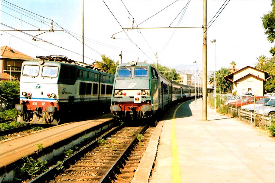
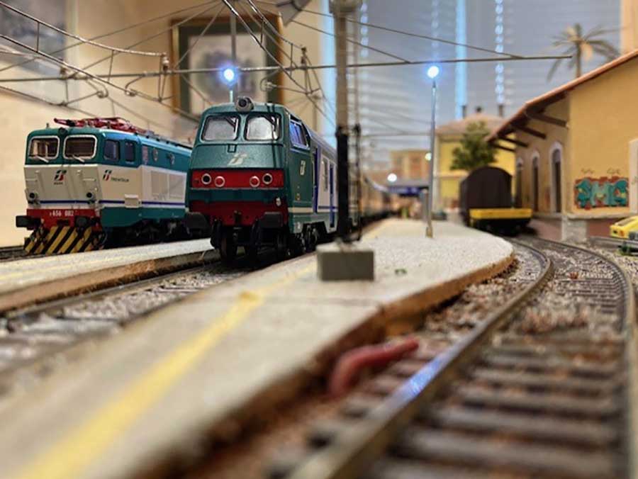
The photos show an E656 articulated electric loco on the left and a ‘semipilota’ or driving trailer on the right, passing in the station, which had a very narrow main platform and no footbridge or subway, so when trains crossed here, the first arrived on the main (left) platform and passengers would board or alight, then the other train would be signalled in at caution to the loop (right) nearer the station buildings. Most Italian passenger stock can be used as push-pull sets with a variety of loco types.
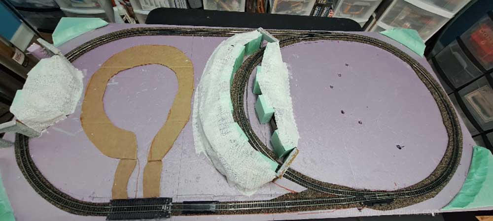
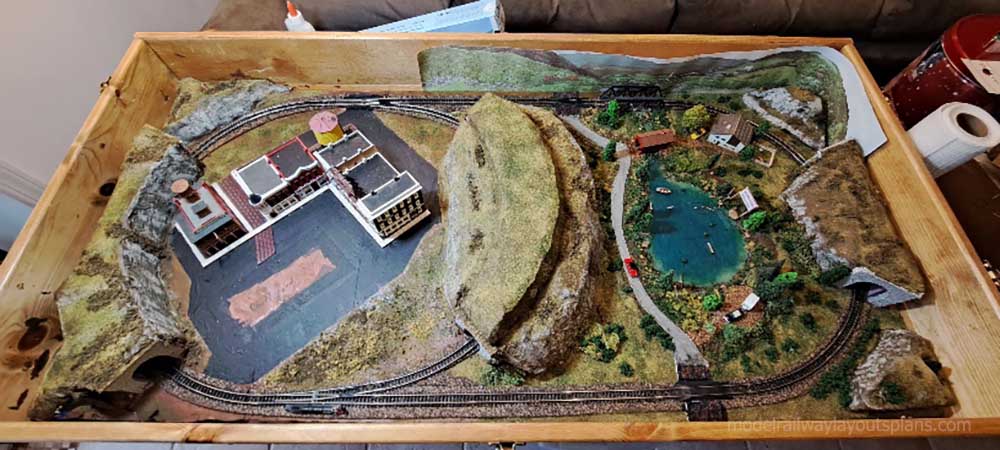
The layout is 11′ by 9′ with baseboards mostly 2′ wide, and is HO scale using Peco track and Sommerfeldt catenary.
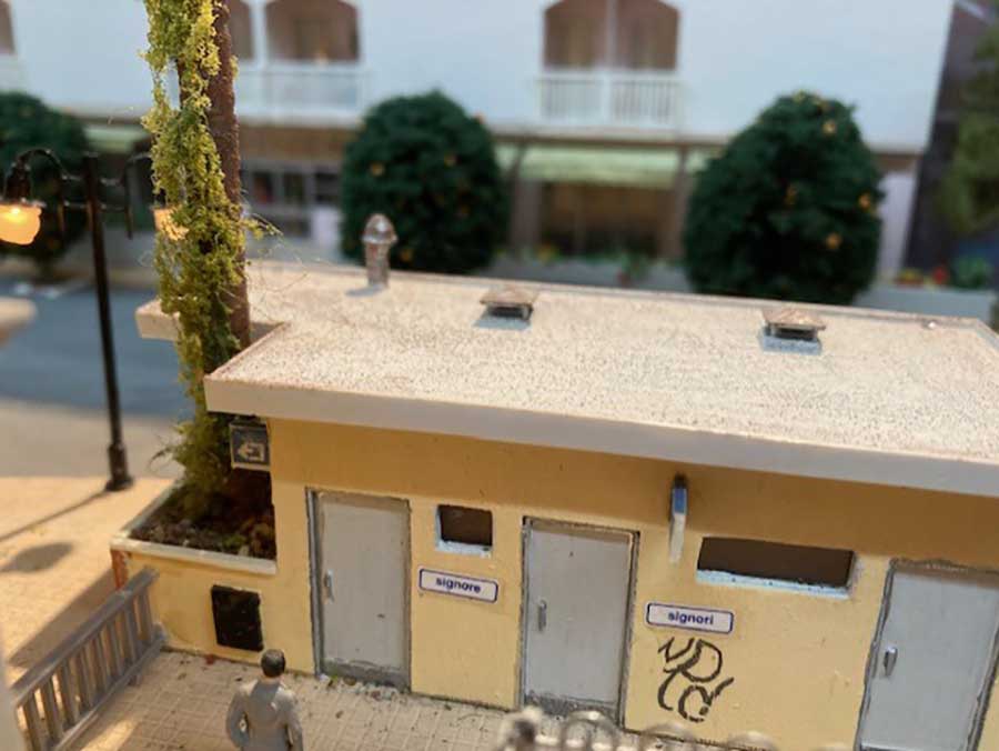
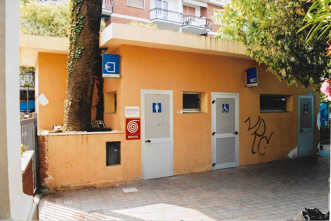
These pictures show the toilet block to one side of the station building. My phrasebook was never up to asking ‘which came first, the toilets or the palm tree?’ It doesn’t appear to have done any structural damage, growing there.
The model is just Plasticard, approximated from a pace count round it and the photo and some doors I had handy. That’s the joy of modelling a real place, it makes you make things you’d probably never have dreamt up. The station had, as well as toilets, a booking office, signalbox, patio with water fountain and a cafe.
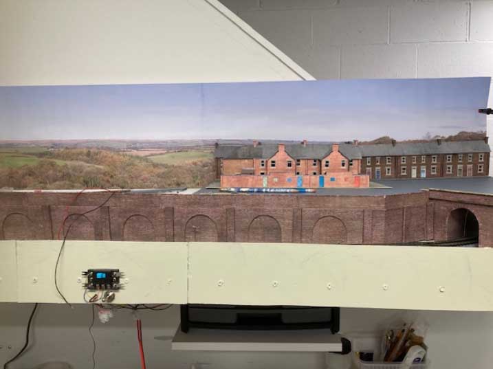
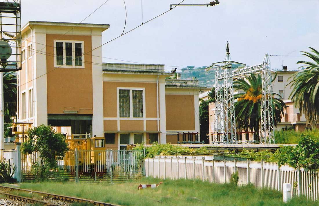
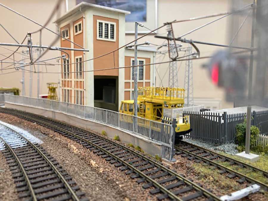
Once again I must apologise for the pictures on the ‘sky’. This is the 3,000v DC substation that supplies power to the overhead live wires. I had to shrink the prototype a bit to fit on the corner of the layout, the switchyard is half the size it should be.
The tall tower has a crane for changing transformers on or off well wagons, the siding being more usually used to house over head line maintenance trolleys. The trolley in the model pic is a brass kit from Linea.
The substation was made with a transparent plastic which I was told would cut and stick just like polystyrene but it was polythene based and very reluctant to be glued, but it ended up OK-ish.
Plasticard modelling:
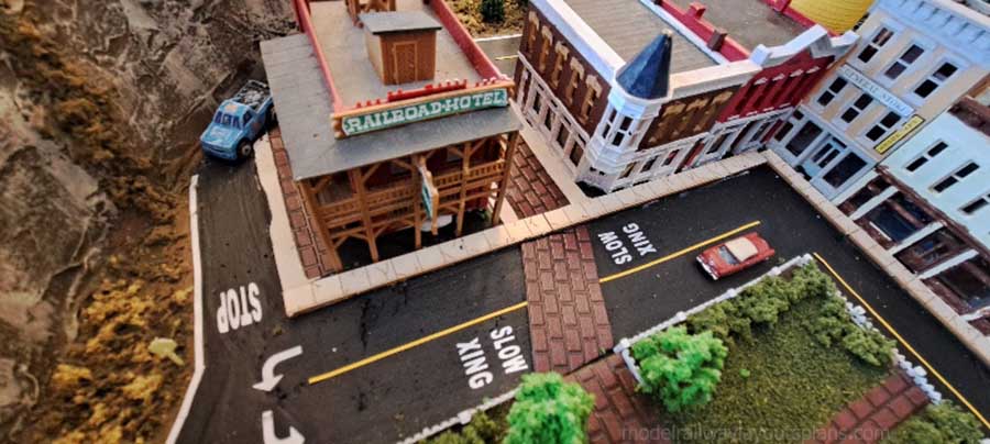
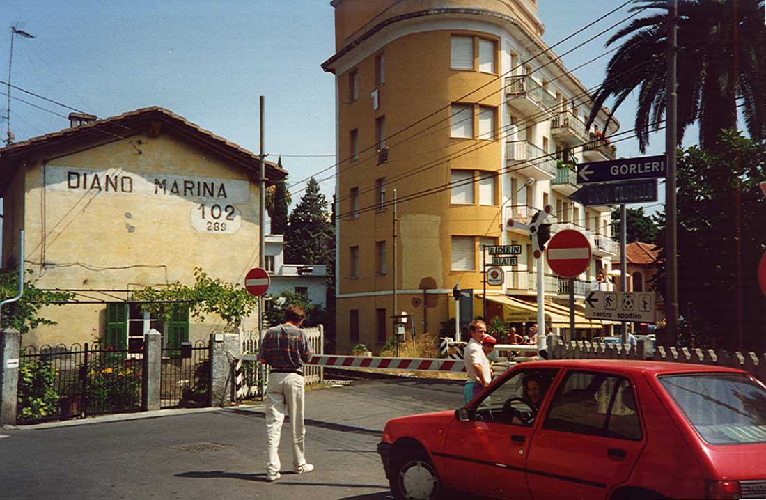
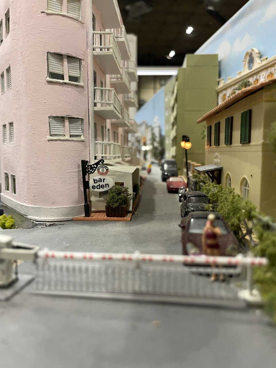
This pair shows the level crossing by the Bar Eden, which occupies the ground floor corner of the huge round-ended block of flats and shops. The bar staff got used to me leaving my seat whenever the crossing bells began to sound. It would often be quite a while before the signalled train arrived and the little street would quickly fill with traffic, luckily it was one-way.
The model crossing is a Viessmann product and although Italian crossing barriers don’t have hanging skirts, the ones on the model were too nicely delicate to want to cut them off – they could certainly do with them as the locals get rather impatient and even push mopeds under them at an angle! I am sad to say I still remember hearing somebody killed here, while I was swimming peacefully round the hotel pool; the shriek of the engine’s whistle and brakes and the ensuing thump are hard to forget.
The L-shaped building was made with a thin plywood frame and ply top and bottom with plastic drainpipe section forming the three external rounded corners and a plasticard facing for the straight walls in between, the various bits being blended together with Humbrol filler. I am lucky with modern Italian architecture as they have plain reveals and recessed electric shutters, easily modelled. Lazy is my middle name.
Plasticard modelling:
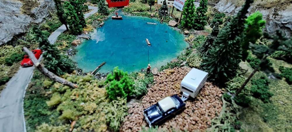
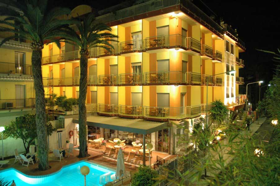
Here is our regular hotel, the Torino, in Diano Marina. I was determined to have it on the layout so had to ‘edit’ it a block north, so it’s just over the road from the station. This also meant moving the swimming pool a tad to the left. The pool is just a coutout in the 1/2″ chipboard baseboard with a bottom and sides of blue plasticard tiles and a layer of clear perspex for the water.
The owners seem to be keen gardeners and went through a spell of enthusiasm for exotic succulents, hence the border of cactii. The grey canopy covers the patio extension to the restaurant. My favourite spot is under the palm on the little protrusion on a lounger with a good book, and well, well, there’s a bloke with a beard just there!
You might notice the model has one extra floor, I did this so it would come up far enough to cover the joint where the backscenes met at 90 degrees – the hotel is low relief and L-shaped so lifts off when the layout has to be moved. But that year, Sue rang the hotel to book a Spring trip and was told “ah, our great regrets Signora, we will still be closed then, we are having an extra floor fitted!” A spooky moment, like sticking a pin into a wax doll… it now matches the model.
Plasticard modelling:
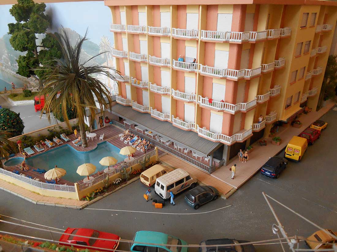
In hindsight, I wish I’d fitted the hotel for LED lights on the balconies, and done a couple of little room scenes in the wider bit above the front door. Too late now, not worth tinkering with. The structure is mostly thin plywood with balcony railings from plastic fencing.
Rod”
A big thanks to Rod for showing us his plasticard modelling – you all know how much I love a layout with a theme, and it really looks like Rod had fun too, which is the whole point.
You can see more of Rod’s layout here: European model railroad.
That’s all for this time folks.
Please do keep ’em coming.
And if today is the day you press the fun button and get started, the Beginner’s Guide is here.
Best
Al
PS More HO scale train layouts here if that’s your thing.
Need buildings for your layout? Have a look at the Silly Discount bundle.