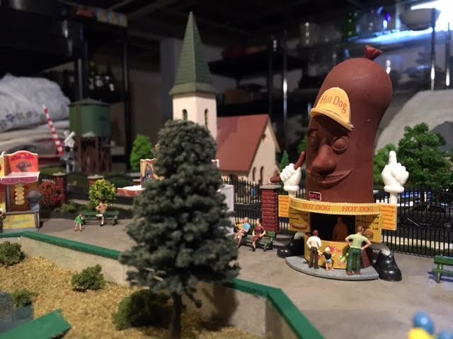
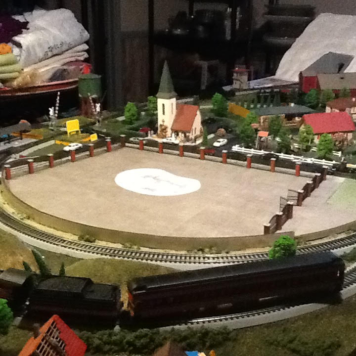
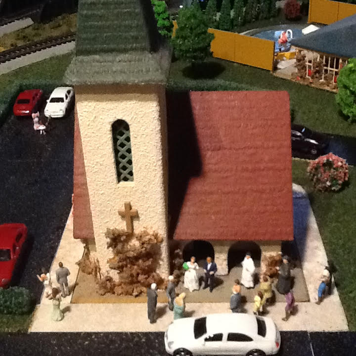
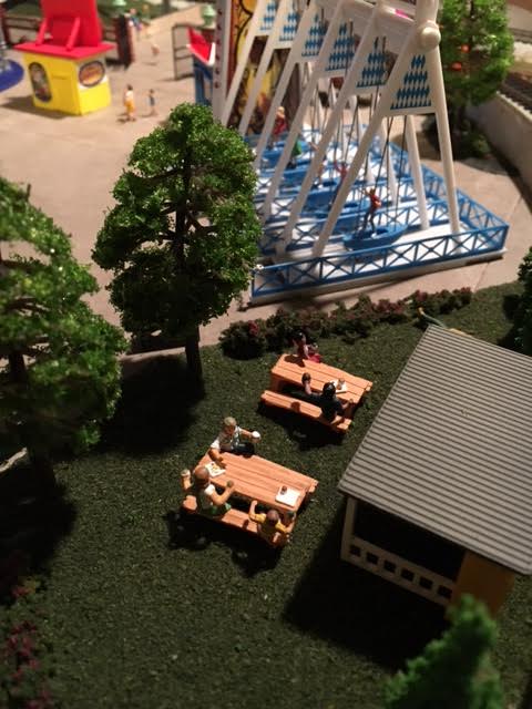
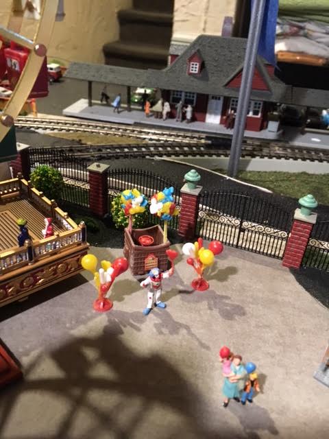
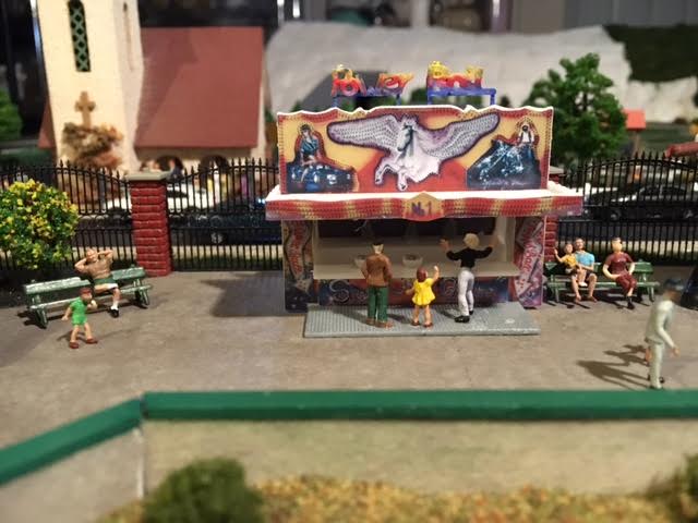
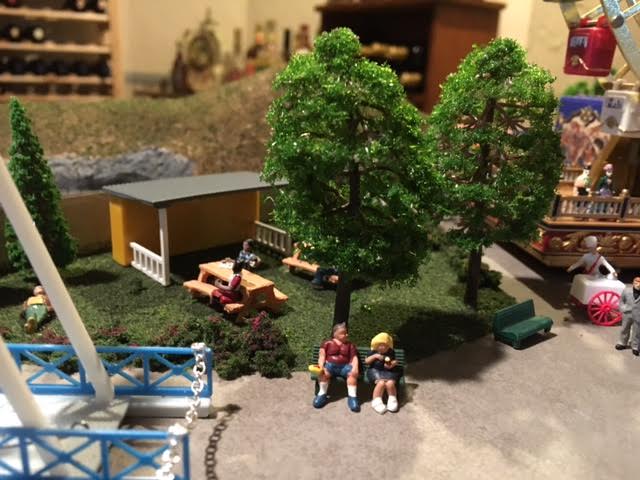
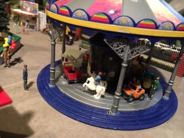
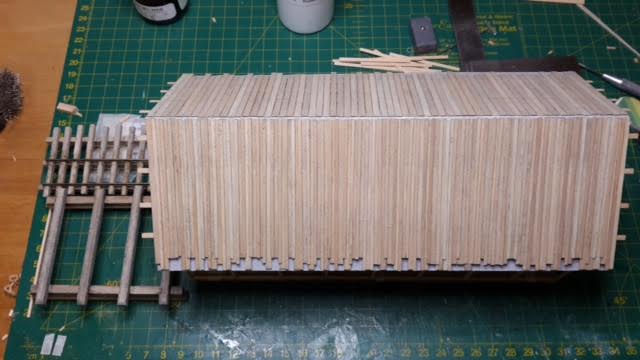
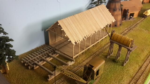
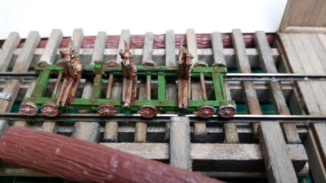
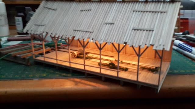
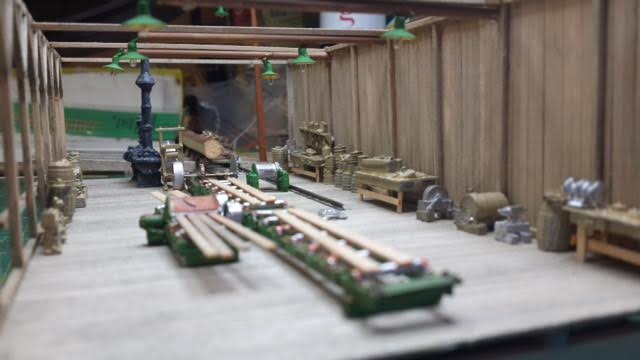
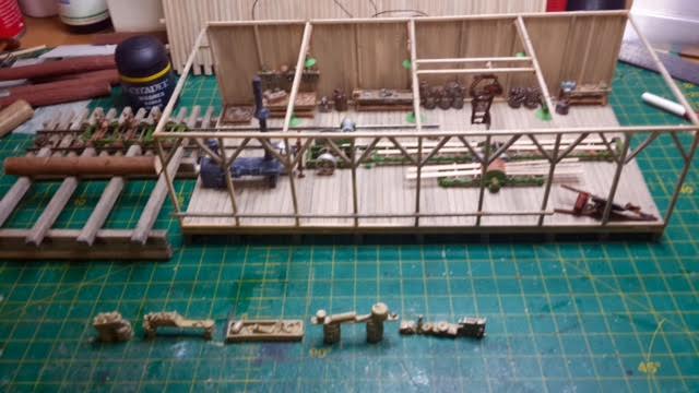
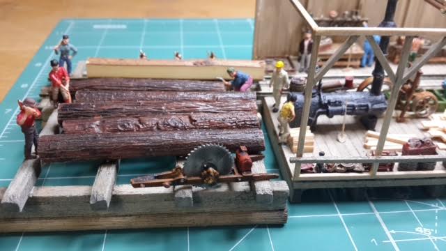
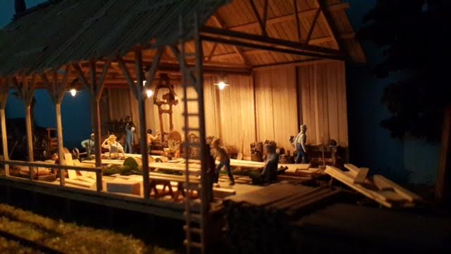
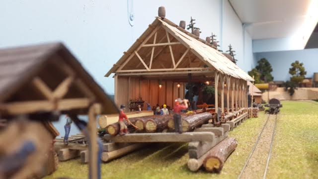
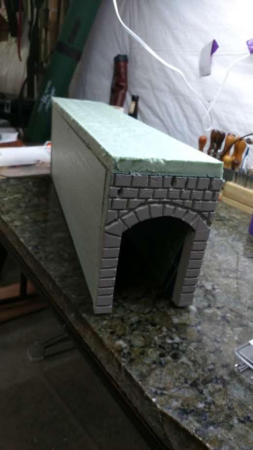
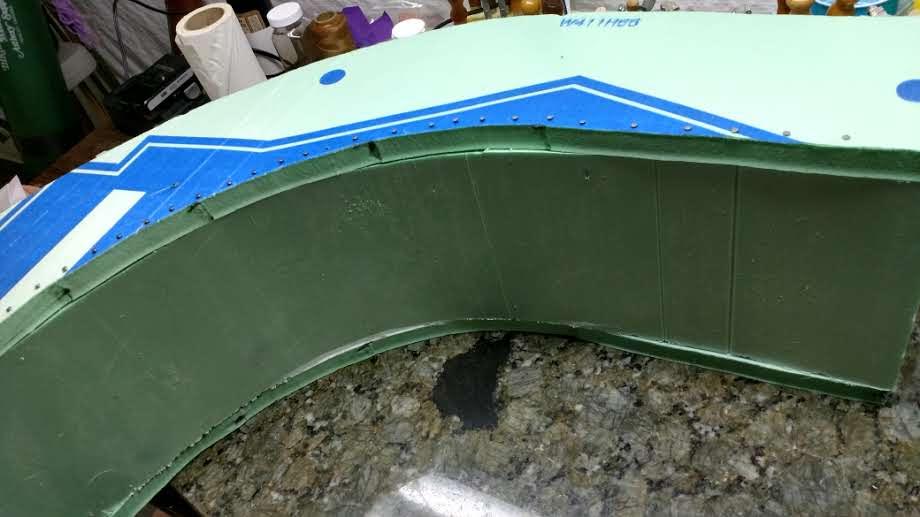
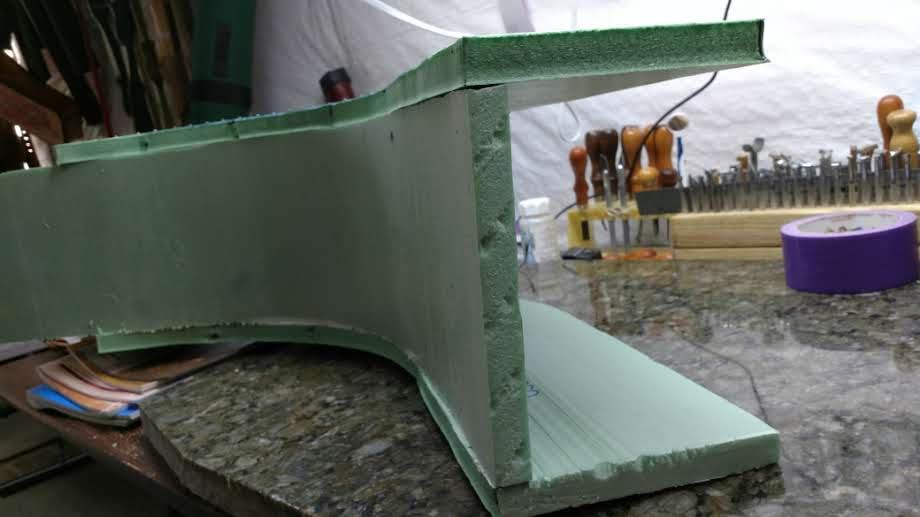
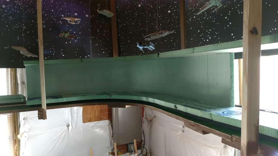
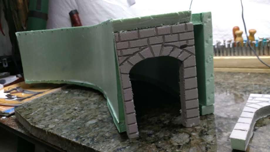
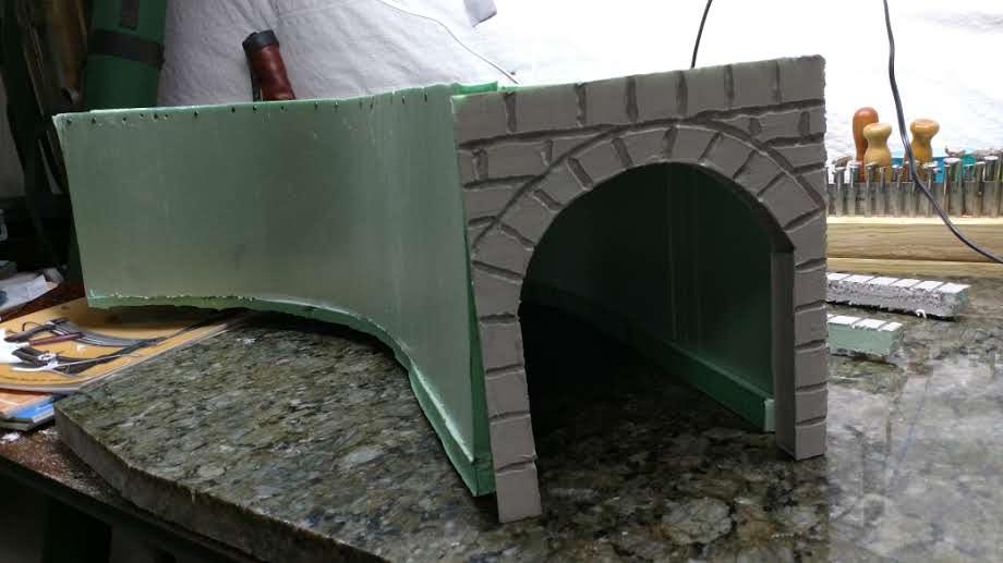
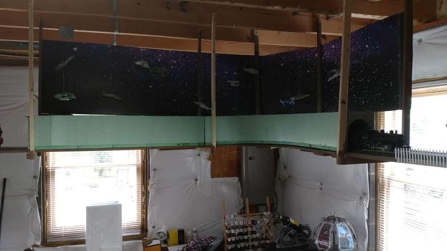
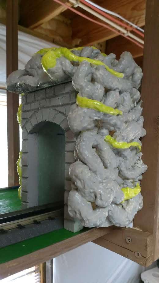
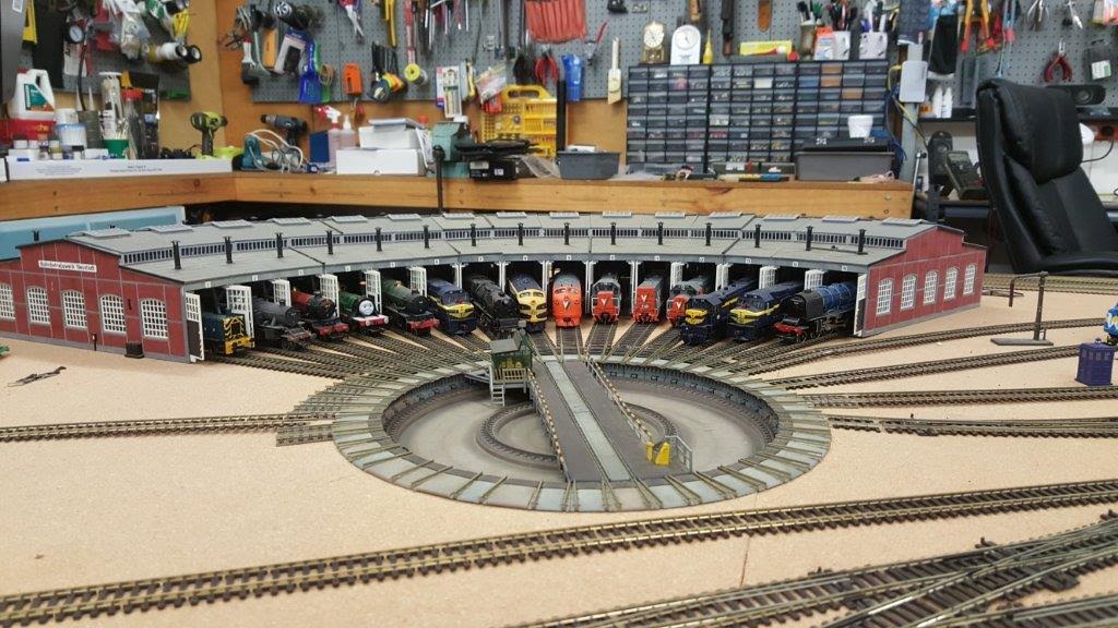
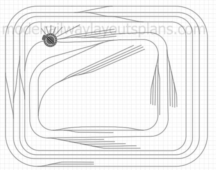
Herb has been having fun with his HO scale model roundhouse and track – really like what he’s done:
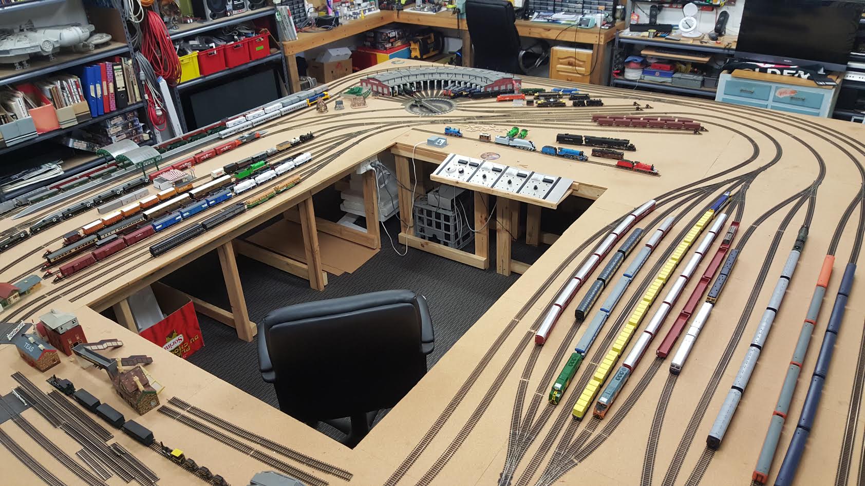
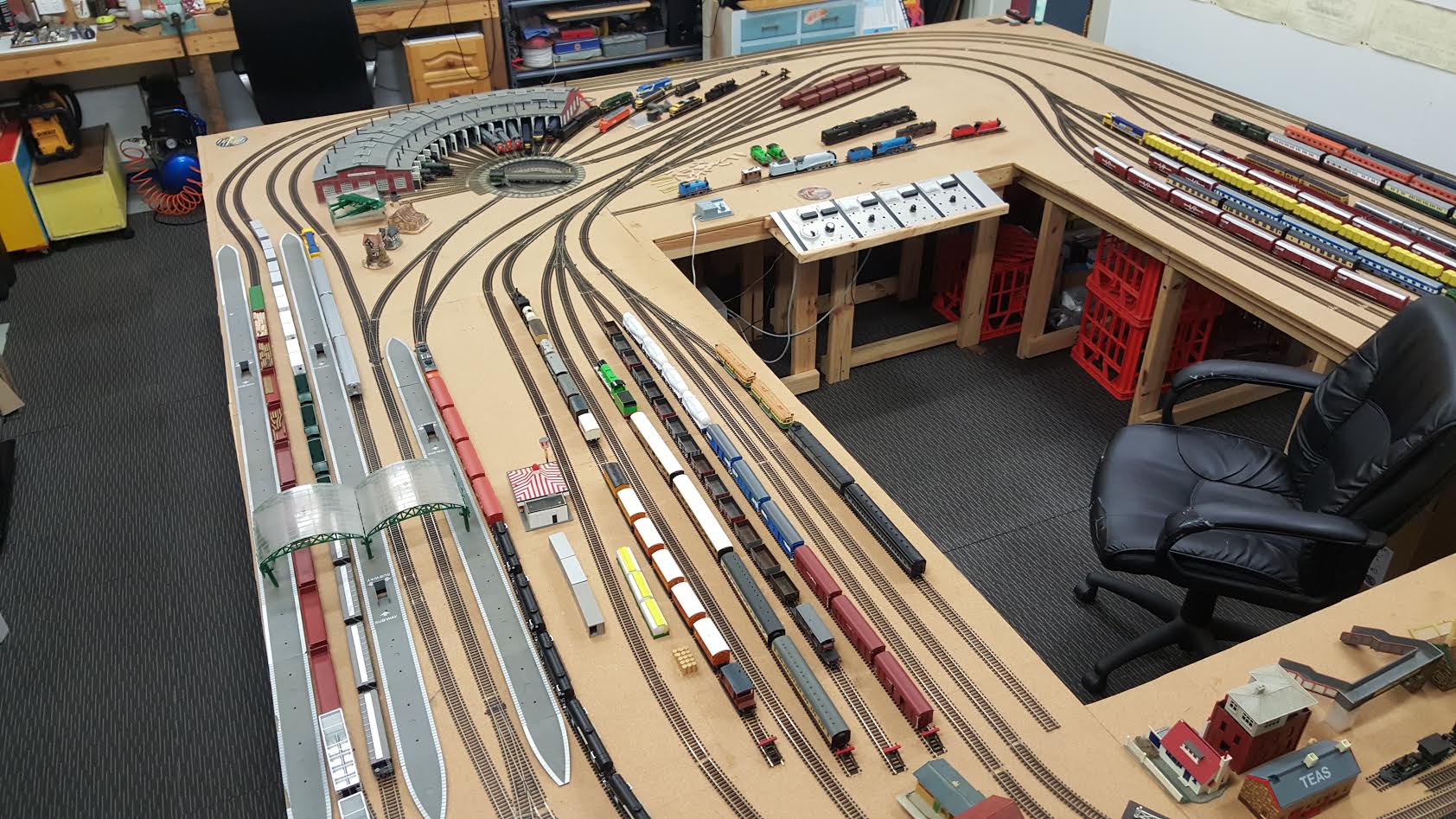
“Hi my name is Herb from Melbourne Australia I enjoy your emails, so i will send a couple of pictures of my layout.
Not much too talk about,& i don’t model any spefic era as my son is austic.
But we get out there & have a great deal of fun & father son bonding time & i believe that’s what’s life is all about.
Plus we get out from under my wife’s feet well that’s all for now.
From Herb & Rick in the land down under.”
“Hi Al,
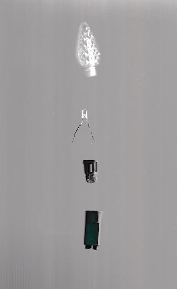
This picture shows a dismantled L E D christmas light from a multi coloured string. When a string of L E D christmas lights stop working don’t throw it away dismantle it and use the L E Ds in train sets, even if you buy a string of 70 multi coloured lights you will have many different coloured L E Ds for your hobbies sets you just need to figure out what resistance you need to use as they can be used on AC/DC, I have replaced the headlights on some of the Diesel engines sure nice & bright, I have also converted the lighting in some of the passenger cars but you also need to make a reversing bridge to reverse + & – without losing the lights. also different colours use different resistance, and some are assembled a little differently so you just need to experintment.
Ken”
“Hi Al.
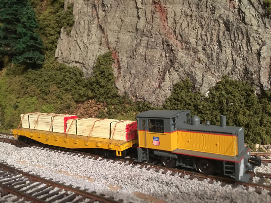
One of the most frustrating and demoralizing events in model railroading is when your short wheelbase or sound equipped loco halts be/cause of poor or dirty track.
Fortunately, manufacturers are now beginning to equip locos with “keep alive” or “stay alive” modules that make this problem a thing of the past.
Attached is a photo of a “stay alive” equipped 4 wheel Plymouth switcher that will run all day through any track configuration with absolutely no power loss.
Truly a pleasure to operate even at speed step 1 while watching the couplers mate.
Mark”
A big thanks to Herb for sharing his HO scale model roundhouse, and to Mark and Ken too.
I real mixed bag today – but enjoyed them all. Just goes to show, you don’t have to have a finished layout to enjoy ’em.
That’s all for today folks.
Please do keep ’em coming.
And if today is the day you get stop dreaming and start doing, the Beginner’s Guide is here.
Best
Al
PS Latest ebay cheat sheet is here.
PPS More HO scale train layouts here if that’s your thing.