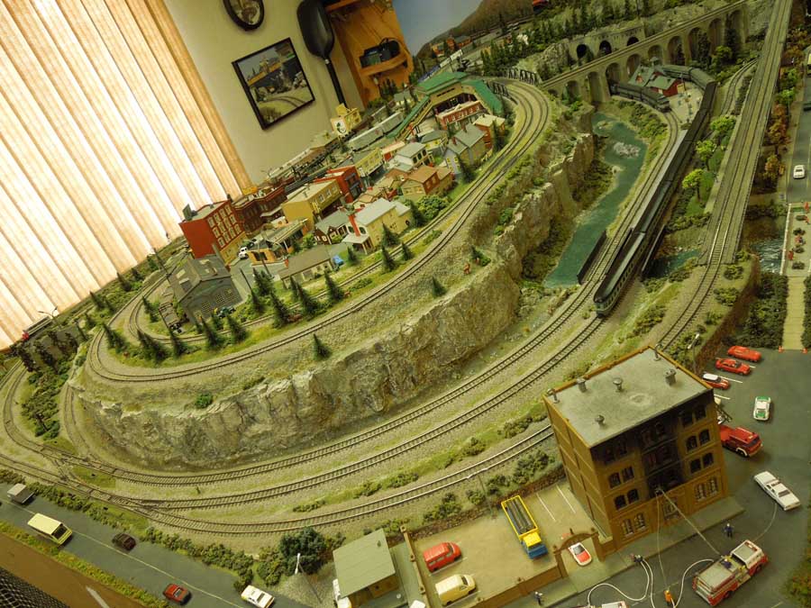
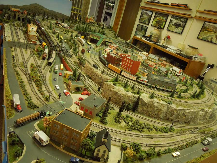
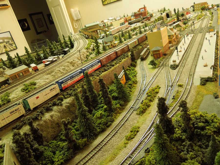
I’ve been trying to set up my HO trains for a while I have noone to talk to about this, but I’m not sure where to start. I’ve been trying to use the new ez track but it doesn’t seem to look real enough or have the flexibility. I have lots of the copper track. Would the copper track make the layout look more real? The room I have is 8×8 and I put a 2 foot hole in the middle of the table. Any help I can get will be appreciated.
Mike”
“Hi Al,
Here are 3 photos of a new signal I made.
This one is a 2 aspect signal, however it can show 3 positions, Red stop, Green go, Green over red proceed with caution.
The signal was made out of 2 bezel leds, a black drinking straw, card for the signal head.
Paul”
A huge thanks to everyone today – especially Brian. Hope you enjoyed his slide show as much as me.
I thought Jim’s layout was fantastic for a first attempt, and I did like the way he’s taken pics along the way.
It just goes to show, it’s all about making a start, so if that’s you, the Beginner’s Guide is here.
That’s all this time folks. Please do keep ’em coming.
Some of you will remember Rob’s Farland Howe layout. He has some wise words on model train curve radius and inclines.
I really enjoyed his video because it shows how you’ve just got to roll your sleeves up and get stuck in to your layout:
Dear Al,
Your readers always are interested in track plans so I have attached one. It is fully up to date and accurate to the best of my knowledge.
I started this layout about 4 years ago. I had come into possession of a DCC locomotive with sound. I did not know what exactly that meant when I bought it. I brought it home and set up a circle of track on the dining table and tried it out. I was hooked.
I started dreaming of layouts and thinking of what I wanted in one. After 4 months of planning and thinking, I finally decided on a flipped over dog bone where at one end of the layout the loop would go over itself.
To illustrate this to yourself, just take a rubber band and twist one end. This I thought would give me an exciting place where trains could cross over each other. I saw one like this once and thought it looked fun.
During this early period before I started building the layout itself, I had a 1200 mm x 2400 mm (4-foot x 8-foot) sheet of plywood on legs in my basement with a loop of track. That way I had somewhere to run a train or two and dream.
Next I determined that 4 inches (100 mm or 25 scale feet in my case) was safe not knowing just exactly what to expect, to allow one track to cross over the other. In the end it turned out to be too much. I am modeling England and realized later I only really need 13- 17 feet or 70 mm maximum in my case.
My scale is 1:76 or about 4 mm to the foot. Originally the locomotives climbed this on a 3 in 100 slope and also went around a 180-degree curve during this climb. It was okay for diesels but steam locomotives struggled. With 2 coaches they were fine, but 3 was a struggle and 4 was impossible. Eventually I changed that but not yet.
I came up with a track plan after 3-4 months and started building. When I got the track laid, I started scenery. I did notice there were some problems with the model train curve radius incline – I talked about earlier – but kept moving forward.
In retrospect, that was a mistake. When I was quite far along on that part, I decided to make an extension and put a tunnel and mountain at the far end. The dog bone got much longer on one end.
This worked well, but the old original curves were just not up to par. I realized I needed larger curves. The large radius curves on the new part really worked well but I wanted some bigger ones. That was when the Big Curve project was born. They are still there and work marvelously.
The inside track of the Big Curves is a 40-inch radius or about 1000 mm. They slowly rise at 1.5 in 100 except where the platforms are. It worked great. I was also able to take out some short curves in an S turn by filling in a small area on one side. I now had smooth sweeping curves on four of the 90 degree curves making up parts of the model train curve radius dog bone.
When all this was working smoothly I found myself yearning for longer trains. Howe street Station was designed for 5 coach trains, but I could not run steam trains that long yet.
The next project was the Shell Hill extension. I extended another 5 feet (1500 mm) from where the original troublesome curves had been where they went around the hill and installed foam inclines at 2%. When that was done I had the layout I have now except for some fine tuning, which includes the addition of the Far Moor line, the camping siding, the steam shed and the diesel maintenance building.
That is the story of Farland Howe. It runs smoothly now and trains up to 7 coaches regularly round its spacious curves. The layout has grown to 22 ½ feet by 13 ½ in a U shape.
The most important thing I have learned with my experience is that model trains pulled by locomotives can only reasonably climb an incline at 1.5 in 100 to 2 in 100. Remember in the real world where they needed much more traction, they put more motors on more of the wheels like on subway car and tube trains or keep the inclines modest. Model trains don’t allow multiple motors throughout the train yet. If you cheat on this rule, you will be making compromises from that point on. Your layout will have problems. It is the basic physics of coefficients, weight to friction. It is nature and you just cannot cheat. The other thing is loading gauge. No time for that one now.
The attached video is a little old. Some time has passed since it was made, but I think there are several valuable nuggets in to for newer modelers, particularly with model train curve radius. It also explains the Farland Howe layout and how it evolved over time. It is my journey towards what exists now.
Thank you Al for all your good works and giving folks who are starting out a chance to hear from folks with experience and have already made a few mistakes. It is sharing at its best. My advice, if it doesn’t work as well as you want, tear it down and do it differently. No need to live with it.
All the best,
Rob”
A huge thank you to Rob for putting the video together and writing the narrative.
Who would have thought, one DCC loco would lead to all this?
Well, that’s what it’s all about: making a start and enjoying yourself.
Glyn has been in touch again with his Faller bridge HO scale – and it left me speechless. It’s not hard to see why.
I hope you enjoy this as much as I did. All images are clickable by the way.
“Hi Al – I’ve been traveling a lot lately but was awaiting the arrival of my Faller bridge HO of the Bietschtal bridge to complete the double main line addition to the back of my layout.
The tracks crossed my river-waterfall feature at a higher level and I needed the 43″ span of this bridge to make the project work.
It finally arrived and I spent most of last weekend building this highly detailed kit 43″ long and 15” high.
I also needed to re-route my logging road through a side tunnel alongside the ravine so, inspired by John’s amazing use of your stone wall printout, embarked on a scratch built tunnel portal replete with curved stone abutment at the entrance to add some character.
That printout is amazing and probably the best piece of modeling landscape material I’ve ever purchased – truly incredible what you can do with it and a little imagination!
So here goes with the project step by step.
The support spans were built first – incredibly tedious as the catwalks have to be constructed within the bridge spans after everything has been assembled, the handrails being the worst part.
The Faller bridge HO stone arch supports added – these were a strange beige colour and not very realistic so I sprayed them and the bridge with gray acrylic primer then weathered the stone. The centre of the bridge sagged a little without appropriate tensioning of the support stanchions so I built a wooden frame to stabilize everything. Being 43” long this bends easily when lifted!
The bridge’s stone portal were re-inforced with vertical pine struts painted gray.
The support spans with their concrete bases were reinforced with transverse pine blockes glued to the horizontal wooden base at a point where they would provide vertical tension on the main bridge deck to prevent sagging as in real life. That worked pretty well and leveled the deck nicely.
Then it was time for a trial fit into the river’s ravine. I added some styrofoam between the stone portal arches as a prelude to wrapping with Woodland Scenics shaper sheet for landscaping.
Then it was time to lower the bridge construct into the ravine for a trial fit.
Back out we came and I started the landscaping by wrapping the vertical supports and styrofoam with Woodland scenics shaper sheet. This stuff is amazing – so easy to use, no mess and it can be moulded and bent into shape and re-worked until you are happy.Then I stapled it firmly to the wooden frame inpreparation for plastering and painting using the leopard spotting technique described by Woodland scenics.
I’d marked where the river flowed underneath the Faller bridge HO and started laying down river boulders and sandbanks. Then I leopard spotted the plastered shaper sheet with yellow ochre, burnt umber and Payne’s grey acrylic wash, let it dry and added clumps of colored lichen for bushes and undergrowth using a glue gun.
Close-up of the weathered base evolving.
The entire Faller bridge HO on the workbench. Plaster moulded rocks were added and painted, slowly building up the scene and rapids were painted in with acrylic water texture paste and white acrylic paint.Next came another trial fit. This was the empty gap between the track ends:
I needed to make sure the added landscaping did not impede my ability to seat the bridge within the fixed endpoints of the ravine –thankfully it fitted in perfectly.
So now I had the basic bridge construct landscpaed, I needed to add the decking and handrails along the main pedestrian catwalks, out it came again for the handrails to be added.
Next, I lifted the old logging company road and changed its direction to run alingside the newly fashioned ravine edge, together with a quick re-do of the landscaping – playground sand, various woodland scenics turf colours, undergrowth and bushes.
That all worked out well but I needed a scratch-built tunnel portal where the logging road passes through the mountains to my next town, which has yet to materialize on the right hand side of the layout! So I measured and cut out a tunnel portal from a plywood off-cut, coated it with PVA glue.
Then I pasted on the stone wall printout from your website, cut to size and adapted as John described using bits and pieced glued together to make it look confluent,
I bent the excess over the edges of the insides of the tunnel entrance to give the 3-D appearance that John describes.
I needed a little extra support on one side so, for added interest , I added a curved support base as a bulwark and pasted a strip of wallpaper to give the appearance of a curved abutment.
Then I sprinkled on some sand and glued bushes and foliage before gluing it in place and clamping it on. I used another piece of waste plywood covered in paper printout to achieve the interior tunnel wall appearance. So here is a close up of the tunnel entrance.
And here is the final Faller bridge HO inset showing the overall effect with all the bridges spanning my waterfall /river feature.
Quite a deamnding piece opf medling but well worth the effort and it was tremendous fun getting it all done. Now I have to start building the mountains over the double mainline tracks and set up my backdrop (which should have been done first!).
Well, what can I say? An absolutely stunning ‘how to’ from Glyn, on his stunning layout.
But it gets better, this is just part 1 of Glyn’s narrative – so there’s more to follow next time.
A HUGE thanks to Glyn for taking the time and effort to share his Faller bridge HO. I can’t thank him enough.