Had this wonderful lighting ‘how to’ in from Mark.
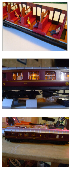
What I love about it is the difference such a small detail makes on a running train.
Big thanks to Mark and please do post a comment below.
“I always wanted to make my coaches look more realistic. I thought they would look great properly detailed and lit up for all to see. The problem with that is, if you are using DC, the best time for your handiwork to be admired is when the train has stopped at the station; and if it’s stopped, then there is no power to the rails and consequently the lights have gone out! Now my teenage son is interested, and I have more time for my hobbies, I thought it was time to tackle the problem. We (sort of) succeeded, so I thought I would share the method, and maybe it can be improved further. Let’s get started with what you will need.
LED’s. Whichever colour you prefer. I tend to think yellow is best for older rolling stock, white for more contemporary coaches, and warm white somewhere inbetween. The brightness can be controlled by varying the value of the resistors you use. I get them 100 at a time from Ebay, 3mm dome shape, round about £4 a packet. The longer of the two legs is the positive side.
Resistors. Again, you can buy large quantities for very little. I find 270 ohm and 680 ohm work well for me, but by all means experiment with slightly larger or smaller values if you want. You can afford to blow some LED’s when they are only a few pence each.
Copper coated stripboard to mount the components on. 1mm holes at 1mm apart.
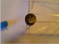
A W06 bridge rectifier. A natty little box that provides a fixed polarity for your LED’s, regardless of the polarity you feed in. Don’t be tempted to buy the first ones you see as they are often silly prices. By waiting and watching, I picked up 50 for £10 including the postage. The top of the rectifier is marked with a “+” so you know which leg provides the positive.
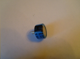
A dual layer capacitor. Best to think of this as a short term rechargeable battery. It charges while there is power to the rails, and discharges to the LED’s when the power is off (You’ve stopped the train at the station). The capacitor needs to be 5.5v, 0.22 to 0.44 farad. 0.22 farad will charge quite quickly, but will only keep the lights on for a short time. 0.33 or 0.44 will last longer, but will also take longer to charge in the first place. You should get 2-3 minutes of lighting from a 0.33f with a 30-60 second charge. Look carefully online and you can expect to pay about £6.50 for 10 x 0.33 farad capacitors.
Wire. 7/0.2 equipment wire is fine. You can even go smaller if you want. My soldering skills aren’t good enough to cope with anything smaller gauge I’m afraid.
Obviously you will need a soldering iron and some decent solder, along with wire strippers etc. Because my soldering is far from pretty, I normally use a multi-meter to check my work as I go along.
Below is the diagram for the unit, and I’ll refer back to it as we go.
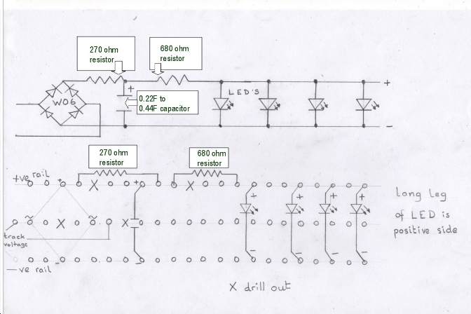
There are 2 ways to go; make a unit with LED’s mounted to go the full length of the coach, or make a short unit and connect that to LED’s mounted another way.
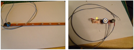
Whichever one you want to build, just make sure your stripboard is at least 3 “lanes” wide. Often I find if I try to cut it 3 wide, one of the edges starts to crumble half way through construction, so 4 wide is easier for me. You may want to work out where your “drilled out” holes will be, and get them done first.
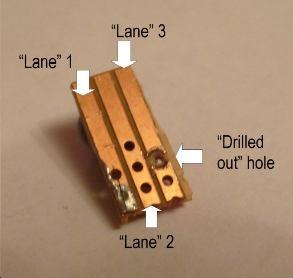
With that done, just follow the diagram. Start with the first lead connection to the board. This will bring power from one rail to the centre lane of the board.
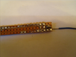
Remembering to feed in from the back, feed your W06 bridge rectifier into the board. “+” to the positive (top) lane, the opposite leg to the negative (bottom) lane. One of your side legs will go in the hole next to the lead you just soldered in, on the centre lane. The other side leg also goes in the centre lane, but the other side of the “drilled out” hole, as in the diagram. If you don’t drill out this hole you will be supplying power from both rails to the centre lane and it won’t work because you are creating a short circuit. Push the rectifier into the board as far as it will go and solder all four legs in place. Again, be careful to not let your solder spill over the edge of the lane it is intended for. Cut off all four excess pieces of the legs when done, and drill out the next centre lane hole (if you haven’t already done so). Now solder in your second power wire to the centre lane. You can solder both side legs into the same holes as the wires supplying power from the rails, but my soldering isn’t that good. Your centre lane is now complete. Yay!
Work your way along the positive (top) lane as per the diagram. Again, the left leg of the first resistor could be soldered into the same hole as the positive leg of the rectifier, if your soldering is up to it of course. Again, remember to drill out the next hole if you didn’t do it at the start, cut off excess legs after soldering, and check to make sure your solder hasn’t crossed over. If you check this after every step, you will know precisely where the problem is if there is one. Leave the checking to the end and you could be left guessing. The next resistor on the top will finish that lane as far as the main unit is concerned. (Don’t forget to drill out again if you didn’t do it at the start).
The capacitor has 2 legs, one for the top lane and one for the bottom lane. It does not touch the centre lane at all, but sits above it like a bridge. The side marked negative connects to the bottom lane.
If you’re making a full length unit then go ahead and solder in your LED’s where needed. The long leg of the LED connects to the top lane. If you need to fold the LED flat to hide it you can. They tend to fold quite easily up towards the board, but not sideways. Cut the excess legs and check your solder. Test by touching the wires to the rails, give it a short charge, and take the wires off the rails. If you’ve done it right, the lights will stay on (although slightly dimmer). You can now fit into your coach and connect up to whichever bogie pickup method you prefer.
If you’re making the unit only, connect 2 wires (1 to the top lane, 1 to the bottom) to carry the current off to your already/remotely installed LED’s. Test as above with a single LED and you should be good to go.
I have found that yellow LED’s do dim rather more than white ones when the power is removed. It’s probably due to the different resistance between the two colours, but I decided I could live with it. I did also try the lovely self-adhesive LED’s that come on a roll. Although they are ridiculously easy to hide, they dim an awful lot when the power is taken off. I tried various ways to compensate for the difference in the bulbs, but I just couldn’t make it work. If someone else can get it to work please let us know. I would rather use those as they are so much easier to work with.
Mark”
And now I’m going to do something I thought I never would.
Slowly over the years, I’ve been getting more and more mails from mails from folk trying to find old posts.
I’ve always resisted putting a search box on because I don’t want this to be just another train site. But as the blog grows, it costs me more and more to run it. I don’t mind the time (I enjoy it). But as the mailing list grows, so do my costs.
So what to do?
I’ll tell you. The search box. If you’d like to ferret through years and years of posts, and find all the ones relevant to what you’re doing right now in your layout, you’ll love the ‘search box’, which I’ve called the Golden Key.
But it comes at a cost. Sorry. Don’t worry though, it won’t break the bank – just $19.97. And that’s for life too. So one payment gets you a life time of searching. You can search until the cows come home, it’s yours for good.
You’ll also be supporting this site too because it’s starting to dig in to my coffers a little too much for my liking (and way past breaking point for the ray of sunshine known as Mrs Lee.)
Here’s what ‘the golden key’ will do for you. Press play and have a look:
Anyhow -I’m sure it will help some of you out, and it will certainly help me out. You have until Tuesday if it tickles your fancy.
That’s all this time folks. A big thanks to Mark.
Latest ebay cheat sheet is here.
Best
Al