I got this tip in – I thought it brilliant. Anyone done it?
“Alastair,
Great ideas you send me. Here is one for the viewers.
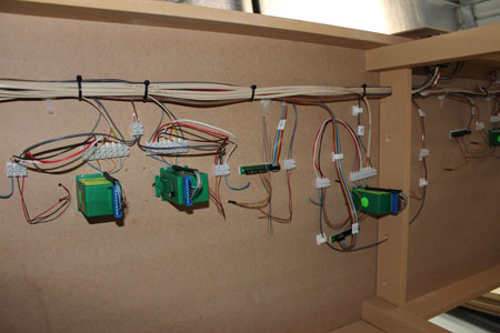
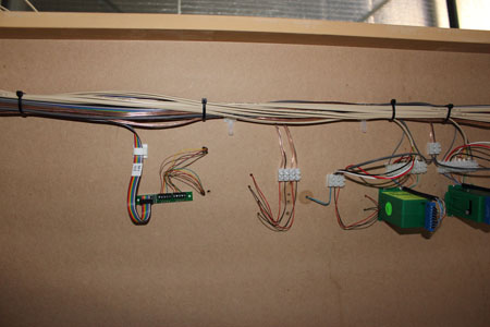
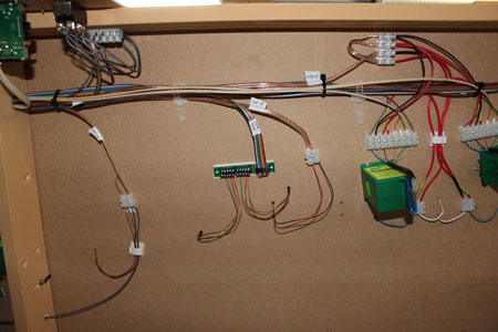
If you are wiring a model railway and want to keep your wiring neat and tidy, use old Ethernet cables. There are 8 wires running through so you can wire points, controllers and other things – without your wiring looking a mess.
It works well if you have a Gaugemaster D controller – 2 x 2 for the Line A and B, then 2 out for the DC (for lights) and 2 out for the points = 8 lines out on the Ethernet cable.
Cheers
David”
Barry has very kindly sent in this expanded explanation of his wiring – and answered a stack of questions too! His original post is here.
Al.
“Hi Al, sending this email to explain some details on my test track.
I am running a Digitrax “Super Chief Extra” DCC system, which uses a protocol called “Loconet” to communicate to all the digital components.
The system comprises a “PS2012” – power supply, a “DCS 200” – command station, and a “DT 402” – throttle.
The PS2012 comes with a “YC52” Y cable, which has 2 x 5amp self-resetting current limiters built into the 2 cables (I am only using one leg of cable).
I have a “Powertech MP3097” – power supply to run all accessories which supplies 13.8v at 10amps constant. I use LM7812 voltage regulators to each of the Digitrax and accessory equipment, as this provides a constant 12v 1amp supply.
If anything draws more than 1amp, the LM7812 will cut off power, so it can act as a self setting circuit breaker as well. I did burn out 4 Digitrax DS64’s using power from the PS2012 (the other leg of the Y cable), but Digitrax has a no fault repair/replace 12 month warranty.
In answer to caw1, who was not sure of what he was looking at:
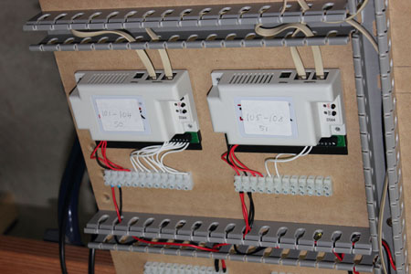
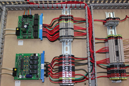
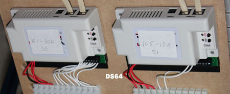
In the DS64 picture – it shows 2 Digitrax DS64’s, which control the switch/point turnouts.
The numbers 50 & 51 on the labels refer to their board ID address, and the numbers 101-104 & 105-108 is the address of each point/switch on the track, and as I am only using 3 points and a double slip, I am only using address 101 to 105.
The white wires going into the DS64’s, are the point/switch position indicators, as some software can use this feature to ensure correct turnout position – good for hidden or hard to reach areas.
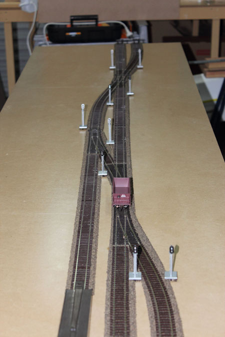
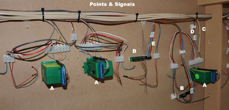
The Points & Signal picture shows;
A – the tortoise switch machines,
C – 6 core cable from tortoise NO & NC contacts for positive switch position,
D – fig. 8 flex (12v) supply from DS64 to tortoise (also note labels on cable, also on control board end as well),
B – Digitrax TSMK (Terminal Strip Mounting Kit) – which has a 10 screw terminal and current setting resistors for LED signals,
E – Digitrax SDCK (Signal Driver Cable Kit) – which consists of 10 core ribbon cable and 10 pin connectors.
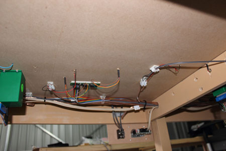
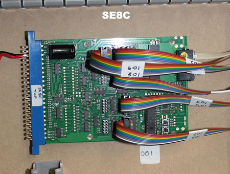
The SE8C picture – is a Digitrax SE8C signal decoder. This device is multifunctional, as it can also act as a turnout control, or occupancy detector. I am using it as a signal decoder, and the ribbon cables go to the TSMK’s in the previous picture. It can handle up to 32 signal heads.
The labels on the cable, are actual signal numbers, not the digital address, and the 001 number is the board ID (which I will have to change – as all Digitrax equipment have a default ID of 1, and it pays to have unique ID numbers. I have not change the SE8C ID, as this will also affect the signal address, the manual has diagrams for this feature, and is not hard to work out.
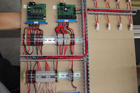
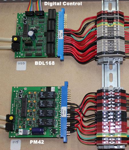
The Digital Control picture – is a Digitrax BDL168 (an occupancy detector), which also supplies power to the power districts/blocks on the layout and its ID# is 20. The 2 ribbon cables at the top, go to 2x(RX4) transponders, which will pick up the name of any loco/rolling stock the can transpond.
This can be useful if you are controlling your layout by computer (which I am), as it can display the name/ID of your loco’s/rolling stock wherever it is on the layout. I am not using this feature at the moment, as it is a Digitrax thing, and the decoders I have put in my other loco’s are SoundTraxx Tsunami’s. The PM42 supplies power to the BDL168 (ID# 15). As I only have 2 power districts on my test layout, not all output pins are used.
In the Red & Black terminals near the bottom, you can see 1 Red & 1 Black bridging link, these are the 2 track A & B power connections (the 3rd connection goes to power the SE8C module).
The output terminals (at the top) go to the BDL168 (except the very top – which feeds the SE8C).
The 4 Black rectangles (with white lettering), are 5amp (each) self setting circuit breakers, for when loco’s derail.
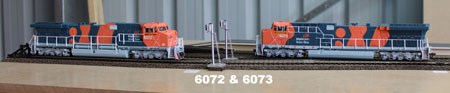
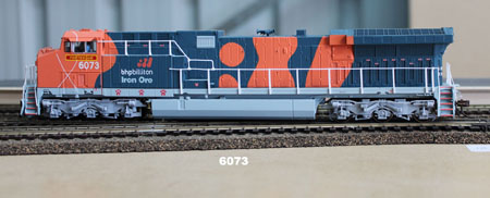
The last 2 pictures are of 2 of my loco’s that I am testing.
Loco 6073 is the reason I got back into MRR again, as I have actually been on this loco when I worked in one of BHP’s rail workshops in Port Hedland, Western Australia. I saw it on eBay one night while working interstate, and as it was well under $300AU, I bought it.
I then bought its sister (6072) from eBay as well, and decided I had better buy some track etc. etc. (most of you would know the rest), when do you stop.
These loco’s are Broadway Limited AC6000’s, come with DCC and 2 huge speakers in the fuel tanks, and they do sound rather impressive. I will send in a video later, when I can get a good external mic. for my Canon camera.
Paul Starr asked the question of wiring identification, I hope some of the pictures show what I have done.
Richard Moses mentioned track power soldering. I solder all my connections to the BOTTOM of the track, hidden by the ballast (which I do not have).
When I start my proper layout, I will solder the connections to rail joiners, which in turn will be soldered to 2 sections of flexi track (which will give me 1.8m/6′ lengths). I use solid core cable (not sure of size – it is small), which go thru table, then into terminal strips (which you can see in some of the pictures).
I also solder my points/switches the same way. I use Peco code 83 & 75 track, and Peco turnouts (points/switches).
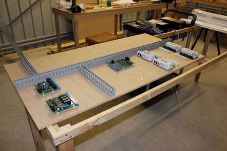
Cameron asked about the ducts and rails. The duct is 25mmx25mm slotted (available thru electrical outlets or wholesalers), same as the “top hat” rail. Being an electrician (still working), I use these material all the time, and never thought about using anything else for my layout. I will go for a larger slotted duct when I start proper layout, as current duct will not carry all the cables.
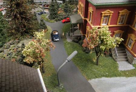
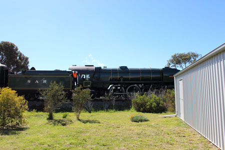
Brian asked about where I got the realistic shrubs from, I am not sure if he had his tongue in cheek at the time, but it is a photo of a real steam engine travelling thru my back yard.
If anyone has any questions, please post below!
Regards,
Barry”
That’s all for this time folks.
Please do keep ’em coming.
And if today is the day you get started on your layout, the Beginner’s Guide is here.
Best
Al
PS More HO scale train layouts here if that’s your thing.
Need buildings for your layout? Have a look at the store.
They are great fun to make and great value too.