Dean’s been back in touch with his latest missive – plaster cloth mountains – and they look great:
“Al, from Dean from New Mexico.
Here is the next installment on my Conejos Valley Railroad layout construction in which I continue the scenery and build a mountain. I’m using a slightly different construction technique compared to how I built the hill in the last installment.
But first, some history if you don’t mind. When the Spanish moved into the new world, they quickly populated Mexico, then moved north to as far as central Colorado (as evidenced by place names such as Alamosa, Salida, Buena Vista, and Pueblo). Towns such as Durango, Antonito, and Chama were named by the Denver and Rio Grand Railroad when they came through and set up the towns as railroad towns.
I picked the name, Conejos Valley Railroad, as it is a real river valley in southern Colorado and is a conceivable place for a real railroad.
What’s in a word! Conejos, means rabbits, and people like me pronounce it conehos, although the Spanish j is more uvular. In an earlier blog, someone (with tongue in cheek) noted a similarity between conejos and cohones. Spanish is all about vowels and here are some examples:
Conejos — rabbits
Cahones — drawers (in cabinets not pants)
Cohines – cushions
Cohones – look it up!
On to important things.
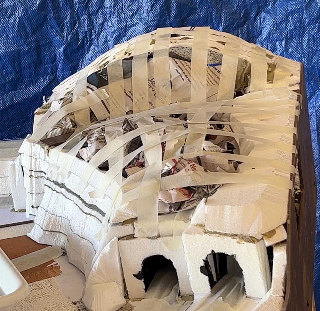
I started building the mountain using layers of cut and glued Styrofoam. But as it got higher, I wanted more internal space, so I switched to an alternate method using plaster cloth over tape and wadded newspapers.
In retrospect, I should have used more strips of tape as the resulting hill was too bumpy. Tunnel entrances were cut from the Styrofoam.
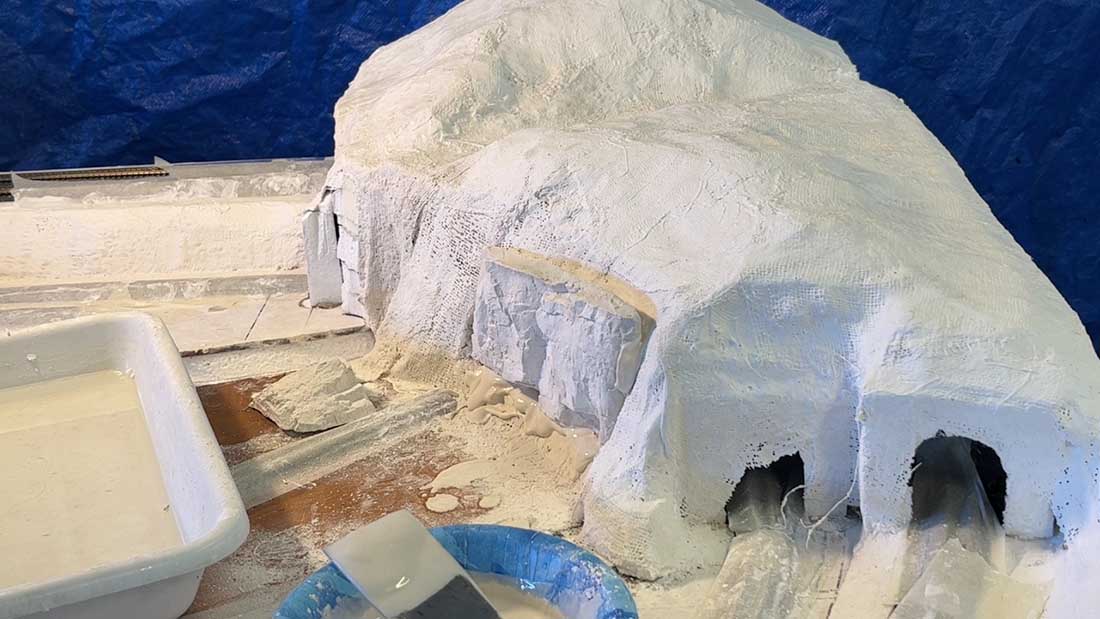
The formed mountain was covered with two layers of plaster cloth soaked in water.
Rock castings (using Hydrocal) were placed into the mountain and plaster mixture was placed between them and carved to form more rock formations.
Incidentally, I waited too long, and the set plaster was very difficult to carve.
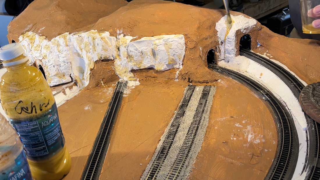
I painted the areas representing dirt with my usual paint mix, and then spotted the rocks (with Yellow Ochre and Burnt Umber) and colored all the rest of the rocks with Black.
All stains were acrylic artist’s paints highly diluted in water.
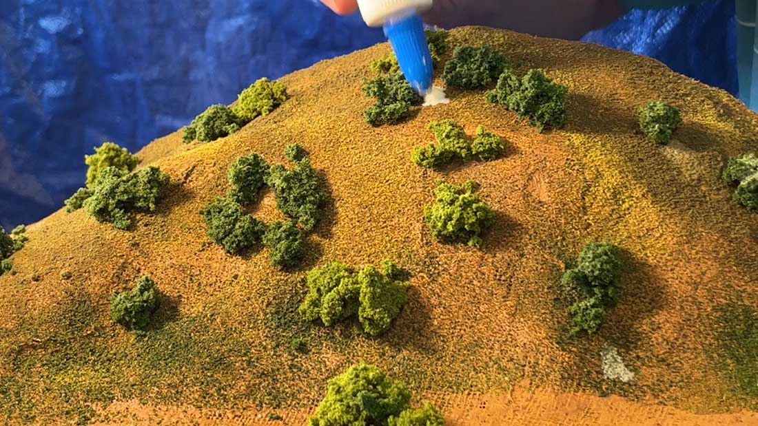
I then coated the surfaces with dilute White Glue (1 part plus 1-2 parts water) and spread ground cover somewhat randomly over the wet glue.
I used my usual Earth, Yellow Grass and Green Grass Fine Turfs (all from Woodland Scenics). I used minimal Green mostly along the river bed.
Finally, I glued (with White Glue) Light Green, Medium Green, and Dark Green clump foliage (Woodland Scenics) to represent trees and bushes.
I’ll add deciduous trees along the river when I form it and the waterfall through the valley.
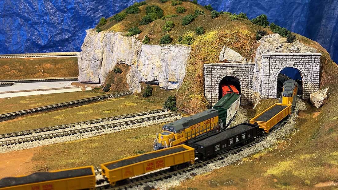
The stained tunnel portals were fastened in place with Joint Compound. And here is the final result. After cleaning the tracks, I ran some trains which you can see below.
Next, I’ll add a small central hill, streets and roads for the towns and industries, and finish the river and waterfall.
Thanks, Al, for all your support.
A big thanks to Dean for sharing his plaster cloth mountains step-by-step.
That’s all for today folks.
Please do keep ’em coming I’m nearly out of stuff to post…
Brian’s been back in touch with a cautionary tale on track curve radius:
“This saga started nearly ten years ago when I retired and decided, with the financial manager’s consent, to build a new ‘engine’ shed in the garden to house an N gauge railway,
which you will have seen in previous videos, and shown again a few days ago on Al’s daily ‘blog’.
It was all planned back then on paper incorporating mostly Peco set-track curves giving the maximum curve radii in the available width of the layout – Peco curves No.1 ST12
and No.2 ST15.
As the layout was planned on three separate levels, I did use some flexible track to make the curves on the lower level to reduce joints (and possible long term
problems).
Now despite what everyone says about layouts never being finished, within 18 months Grandpa’s Wonderful Railway (GWR) was complete with scenery and running smoothly to the Grandchildren’s delight and that’s been the case for several years since.
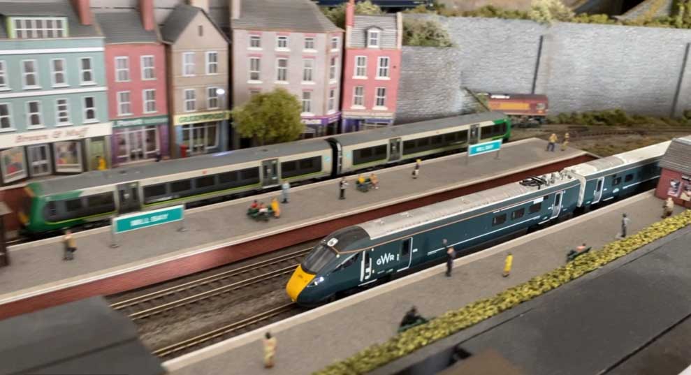
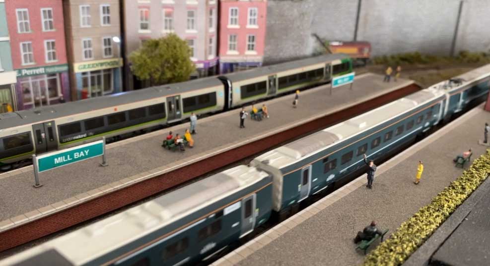
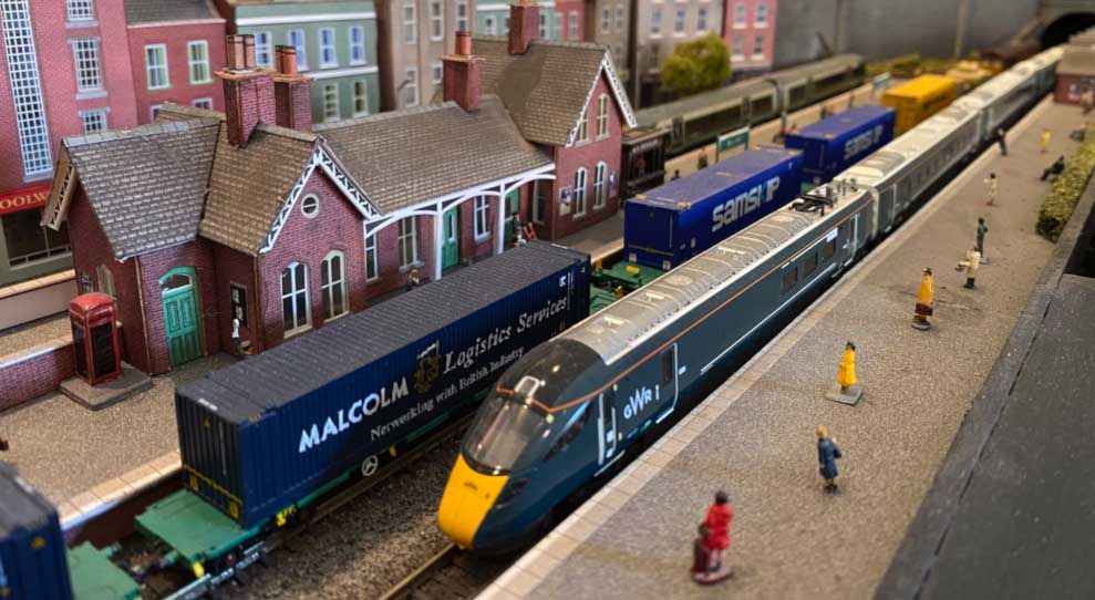
However, things started to go awry back in 2021. That year, Kato released their Hitachi Class 800 five-car model in N gauge, in both UK operator liveries, GWR (Great Western Railway – Intercity Express Train) and LNER (London North Eastern Railway – Azuma).
The Class 800 (Electric/Diesel) trains came into service in the UK in 2017 for GWR and 2019 for LNER. I had to have one on Grandpa’s Wonderful Railway!!!!!
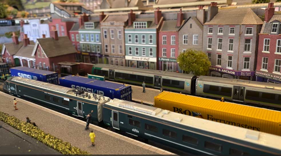
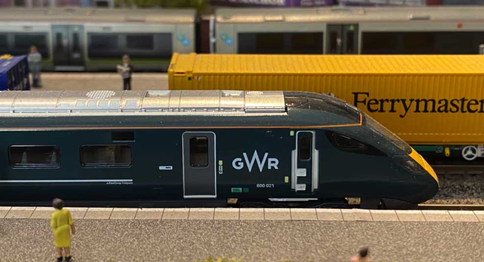
Mine arrived, and as expected with Kato (you may remember my Kato Orient Express post/video on Al’s blog) the engineering and detail were exquisite. Out of its presentation case, and on one of the bottom level tracks, it looked great.
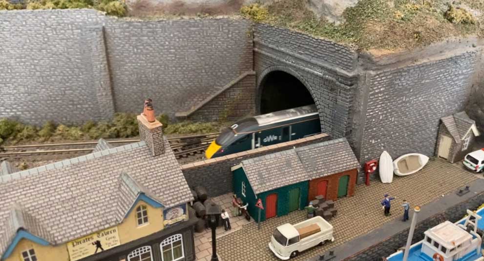
On the parallel track in the other direction was a Virgin HST (Class 43). They both disappeared into the tunnel but didn’t come out! Investigating, the two trains had made contact on the curves at one end of the circuit and derailed.
I had reduced the radius on one of tracks in order to form a reasonable size inspection ‘hole’ in the baseboard for me (or one of the Grandchildren) to clean the track from underneath.
I hadn’t had problems before on these curves with other trains, so it was obviously down to the Class 800 longer units. The only solution was to run each train on that level separately, one in the station and the other operating – not a major problem.
When Al put up one of my previous posts recently, I thought it would be a good idea to put together a video of my Class 800 running and give a cautionary word on ensuring curve radii are maintained on parallel tracks.
So, in an effort to identify exactly what I’d done and give accurate information, I went out to the layout this morning to do that.
Unfortunately, in eradicating spiders’ webs from the offending corner the hand held vacuum cleaner nozzle clipped the track and dislodged the flexible track joints which formed the curve! The track separated, sprung out of the sleepers and is now ruined!!
On a readily accessible part of the layout, a repair would be reasonably straightforward, but the damage is to the lower level circuit, and very difficult to work on. I’ll now have to think of a way of repairing the damage without removing the baseboard, track and scenery above it.
Morals of the story –
1. Make sure that you maintain recommended spacing between parallel curves for various trains. Ideally, try and include the maximum radius possible.
2. Make sure that you have access to any hidden track for clearing derailments and cleaning track.
I hope you enjoy the Kato Class 800 video I’ve included.
Best to all.
Brian, Wokingham, UK”
A big thanks to Brian for sharing his track curve radius advice – parallel curves feature quite often on the blog, clearly the are particularly troublesome.
Please do leave a comment below if you have any advice to share.
That’s all for today folks.
Please do keep ’em coming – it’s still looking like I might be putting my feet up in a day or so.
Tony’s been back in touch – this time with his church kit build, well it’s more of a kit bash as you’ll see:
“Hi Alastair-
Thank you for recently re-posting my “Riverside Local” diorama. It was fun reading it again- especially all the kind comments.
Here’s one final photo- I completed the far side bank since the posting. I have also added a partial backdrop. It is only temporary, but it gives some depth. It is just an enlarged photo, but I took a lot of time looking for the right one. I found it is best to be a faraway view and in soft colors.
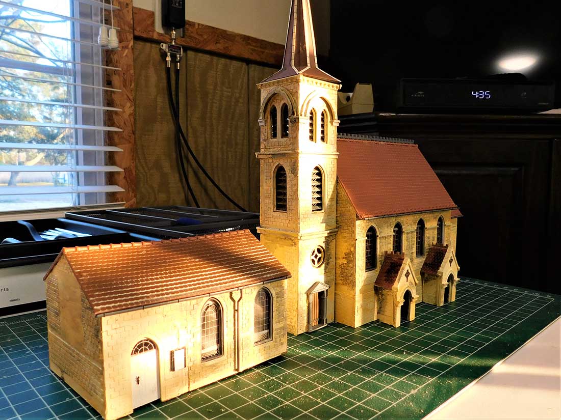
The post reminded me that I haven;t sent anything in lately, so here is a kit bash that I recently completed. This is a model of Christ Church, Chalford – in the Cotswolds.
The actual church-
You can see that I reduced the size by 1 window in each part, but otherwise stuck to the basic design of the church. It will become part of the layout I am planning which will be centered around Chalford on the line from Swindon to Gloucester.
I plan to model the section between Brimscombe and the Sapperton tunnel- circa 1956. I chose this area for a few reasons.
First, because my mother was from nearby Nailsworth and, having spent much of my youth in London, I often rode the train (usually headed by a Castle) from Paddington to Stroud to visit my cousins and grandparents.
The section from Kemble to Stroud really puts you in the Cotswolds and it is very scenic. Many great memories!
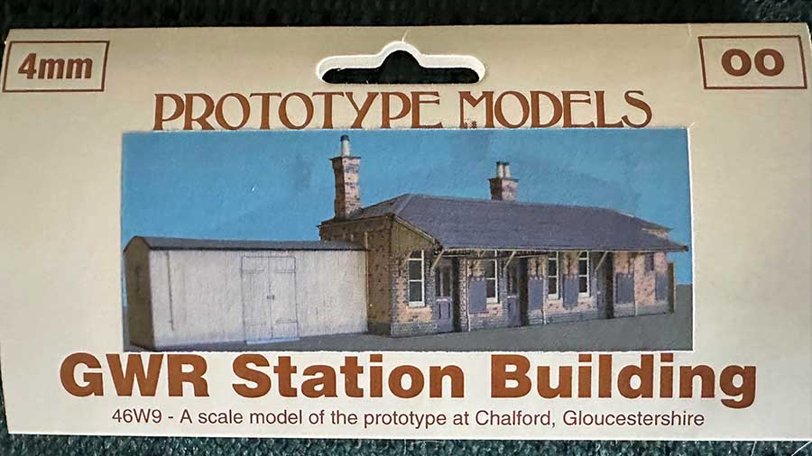
Although the Chalford Station did not survive, there is a very nice card kit available. For many years, an autotrain ran between Chalford and Gloucester- which will be interesting to model and operate.
The Stroud Valley had been a center of industry since the 1700s. The Stroudwater Canal was opened in 1779 and the railway (GWR) opened in 1845, although Chalford station didn’t open until 1897. If I am not mistaken, there were 13 stations and halts on the 12 or so miles from Chalford to Gloucester.
There were numerous mills along the canal and the autotrain was very much a workingman’s railway. They were originally woolen mills and many were still in use in the 1950s for a variety of industries- and many are still open today. So, lots of operational and scenic potential.
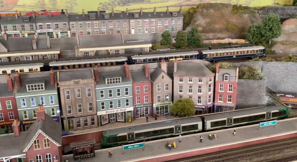
The autotrain was so-named because the driver could drive the train from the engine or the carriage- saving the trouble of running the engine around in Chalford. In the photo the train has crossed over to the down line and the driver is in the carriage, ready for the trip back to Gloucester. The fireman, of course, stayed in the engine.
The train consisted of an engine and 1 or 2 carriages. Throughout its life, a variety of rail cars were also used, but I plan to model the steam engine workings.
As you can see, the kit also has the shed that’s in the foreground of the above photo. The building in the kit is the one on the up platform. The down platform has a similar, but smaller building. A second kit will be the basis of that.
This undated photo is probably from the 1920s. You can see the church is on the left and the railway line in the foreground. Chalford station is about ¼ mile to the right. The buildings in the photo are pretty much still the same today as in the photo.
I am going to model the mill in front of the church as well as the famous round house- to the right of the mill- which is next to the canal. The canal is still there but numerous attempts over the years to restore it have mostly been thwarted by nature.
You can’t duplicate this photo today because the area between the road and the tracks is totally filled with trees. The road still looks the same. It’s not really visible, but the road goes under the tracks on the far right of the photo.
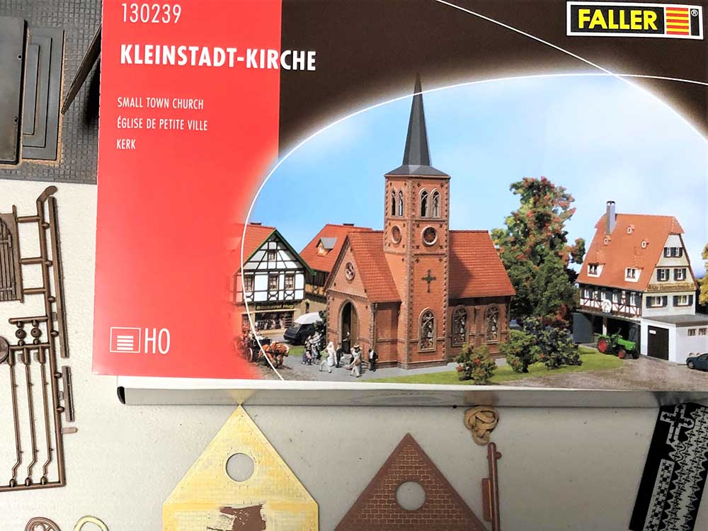
I won’t spend a lot of time describing the building of the church- suffice to say it was complicated and took a long time. I started with a Faller “Small town church” kit. I quickly realized that, due to the fact that the tower of the kit was on the side rather than the end, I would need 2 kits to get enough parts- and eBay again obliged.
There are many HO and OO church kits on the market and I chose this one because the roof line of the tower in the kit matched the prototype – I had no interest in trying to scratch build those angles!
The complicated part was that- although the tower of the kit looks similar, all of the elements are in different places. And there are many parts (such as doors) that had to be added. Each new side is made up of 3 re-located parts and a variety of trim parts- lots of fiddly bits. The main entryways are scratch built and the interiors are partially modeled, although they don’t really show.
A feature that is on the prototype, but not on the kit, is tiles that follow the ridges of the tower roof.
After a variety of different attempts, I settled on simply making the additional tiles out of heavy paper.
A little bit about modelling Cotswold stone. The beautiful stone is one of the things that makes the Cotswolds so popular- but it presents a real modelling challenge.
There are 2 challenges- color and texture. Anyone who knows the Cotswolds knows that the stone buildings and walls constantly change color- depending on the sun and the dampness. Any given building can be golden yellow in the sun or gloomy grey in the rain.
I picture my railway being on a sunny Saturday in May, 1956, so I am leaning toward gold coloring. You can see though, that the second photo of the model has a different look than the first- in different lighting.
I am keeping my fingers crossed that I will be able achieve a reasonable look of Cotswold stone throughout the finished layout.
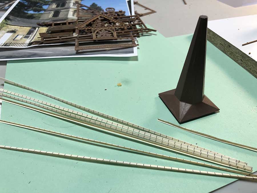
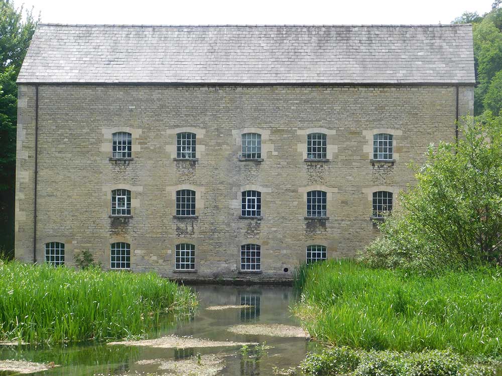
The texture of the stone is even harder to achieve- a subject for another post. But for now- here is part of a scratch building of the Belvedere Mill that I have started. The stonework is all hand scribed, in patching plaster, on card.
Note again, the color difference- I have another photo of the mill that is the exact color of the model.
I was born in 1947, which makes me, I think, just about the average age of the readers! For many years I planned to build a railway in my retirement and always envisioned a large area to build in.
The reality of down-sizing has left me with a room that is 14’ X 22’ which isn’t bad, but it must be shared with my books, hobby supplies, work bench, and the hot water heater.
The layout will not have all the parts I hoped for- but I’ll have to make do. The track is all planned out and I now have to get the annoying bits done- building the platforms, laying the track, and wiring the whole thing, so I can get to the part I like – the scenery! And then the best part- running trains!
I very much enjoy when readers post the entire building of their layout from design to completion and I plan to do the same. Hopefully, I can figure out how to make some videos as well – Dave makes it look so easy, but I’m sure it isn’t.
I guess this is the first post in the series about building “Chalford”.
This can never be said enough. Thanks Alistair, for all you do!
Tony, Kitty Hawk, NC.”
A huge big thanks to Tony for sharing his church kit build – I really enjoyed this one.
Having a theme for your layout really does make a difference, and I think Tony’s is a great example of this.