Kim’s been in touch – he shares how to replace your locomotive lights:
(Oh – and if the link in my previous email didn’t work for you, sorry about that, here’s the correct one: Harry’s layout.)
“Hi Al and modeler’s.This is to replace those 12 volt bulb’s in your locomotive.
To run realistic speeds i find the bulb doesn’t produce enough light.You have to run to fast to show it and normally looks a yellowish glow.
Ive replaced my locomotive lights with 1.5 volt Led’s. Less heat and more light at very low speed’s.
Photo 1 is the led and the 12 volt resistor.And next to it is the factory bulb lot’s of heat very little light.

Photo 2 is the light board in the locomotive.

Photo 3 is the already finished and installed front light with resistor and used shrink tubing to protect from heat and short.
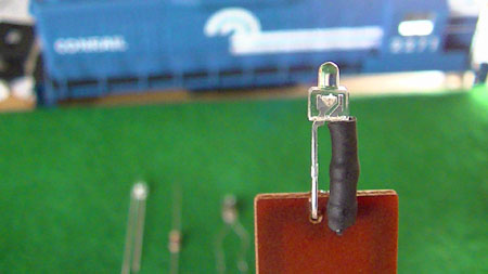
Photo 4 is the factory bulb in the rear of the locomotive.
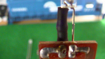
Photo 5 is the Led and the resistor soldered to the possitive lead of the Led.Dont over heat.
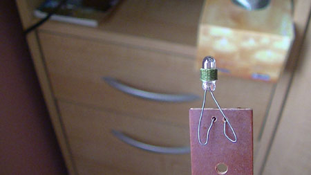
photo 6 is the finished light.

Photo 7 is the Led soldered in place.

Careful to make sure the 2 soldered point’s dont not touch and to use a object to scrap gently between to clear any unwanted stuff and make a clean connection.

Photo 8 is me holding the locomotive at super slow speed and show how bright during the day the Led’s work.

Now next time i am replacing the 2 mar’s light’s in front to real lights.
Basic soldering and a easy fix to spruce up your locomotive lighting. Going to love it at low light.
All Led’s and resistors come in a pack from ebay and cost .99 cents and free shipping for 20 colored led’s.
If any problem’s let me know.enjoy.
Kim”
Now on to Stuart:
“Hi Alastair,
Latest part of my 00 guage model town with the water park and the town pub.
I am really enjoying doing this, I made the pond from model water.
The pub has turned out better than I had hoped. more to come at a later date.
The stone wall I made from a length of cardboard and covered in PVA glue I then sprinkled fine pebbledash which I sived through a cheese grater; came out great.
Keep up the good work sending all these tips and great ideas from everyone.
Cheers
Stuart P”


(See more of Stuart’s layout from an earlier post here).
A big thanks to Stuart and Kim.
That’s all for today folks.
Please do keep ’em coming.
And don’t forget, the Beginner’s Guide is here if you want to stop dreaming and start doing.
Best
Al
PS Latest ebay cheat sheet is here.

Thanks Kim for very clear instructions with good photos to change out these bulbs. And Stuart I like your stone wall the way you made it and lots of cool places on your layout to study too! Nice work.
Dick(little r) from Hardin Mt USA
Some engines may need a rectifier in the circuit as there is running the engine in reverse, thus reversing the voltage will pop the led.
Rgds
Love Stuart’s many scenes of people.
Kim
NonnyM’s point that some engines may need a rectifier is valid with an analog DC system because LED’s can only be powered one way. DCC makes all that go away.
Stuart
Very nice and a fun layout. By mistake I found that white packing styrofoam is made up of tiny white balls compacted somehow. If you soak it in a liquid wash the tiny balls stand out and it looks like a rock wall. If you cut the foam cleanly and then apply a dark wash you have an instant rock wall. Taa Daa.
Big Al
You never fail
When you think of it LEDs will only work with the correct polarity you can install them that the front one is on while going forward and in reverse goes out and the one on the rear lights and vice versa . nice country scene in the layout well done
Powering LEDs with DC that reverses polarity is possible by using a full-wave rectifier chip (do a Google Search on “full-wave rectifier chip”).
Just connect the AC inputs to the track DC (coming from the loco wheels). The chip output will give a constant + & – output no matter the direction of the loco.
Note: The chip will give a two-diode voltage drop of 1.4V from the input to the output.
Question, will this work on “O” gauge, I’m thinking that the light replacement is on HO gauge.
Stuart P
Your layout photos were great!
How did you create the smoke from the house chimney?
No apology needed Al, we all make mistakes from time to time. No need to be sorry !!!!!!!!!
nice layout. good tips on the lights. i like the “smoke” coming from the stacks on the house, wait, they were fake right? lol.
Hi Kim, can you send a link for the LED package on eBay. I could find them. Tnx – alan