Before we get to Jeff’s wiring for DCC layout, here’s a quick missive from Dwight:
(Or just scroll straight down if you want to get the wiring missive!)
“Hi Alastair.
A while back I mentioned that I had dismantled my 12 year old N scale pike, with the intention of starting over with a fresh approach to design and construction.
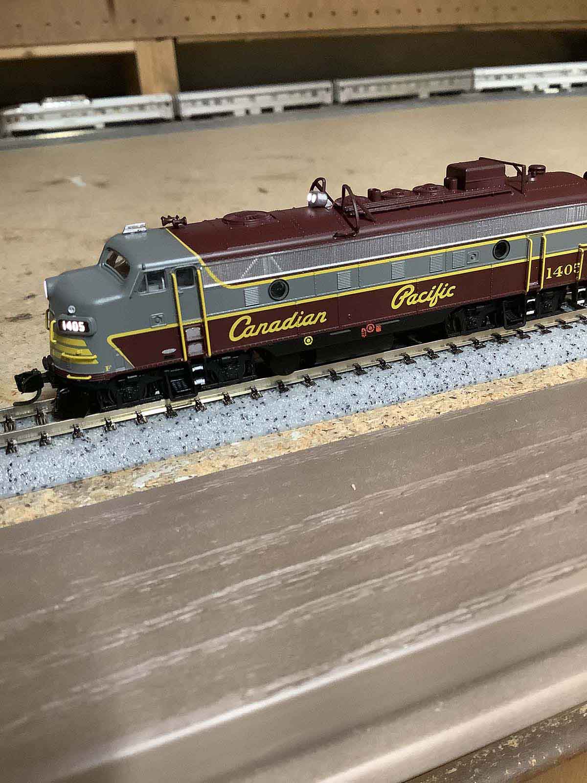
I have yet to make that re-start, but in the meantime I took delivery of a rather special N scale passenger train… “The Canadian”, which was released by Rapido Trains earlier this year.
And to top it off, Rapido just delivered two of the FP9A locomotives that originally hauled this iconic train.
I’m sure many of your readers are aware of this recent offering. However, given your international audience, there’s a chance that some of our friends might not otherwise see it.
So, I wanted to share a a couple of pics in the hope that others will be as impressed as I am with the unprecedented quality, detail, and attention to prototypical accuracy represented by these models.
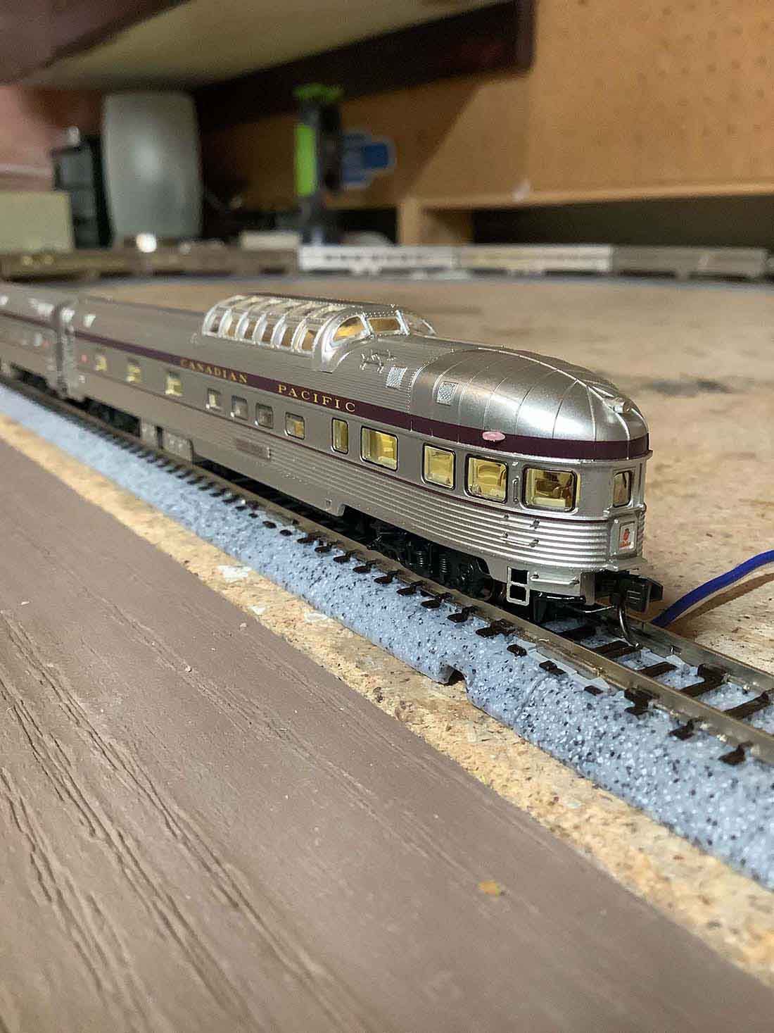
Seeing as I am between layouts at this time, I had to cobble together a Kato Unitrack oval on my workbench, so as to see the train in operation, and to break in the locomotives. I hope that my mediocre photographic attempts do them justice, since they truly are quite extraordinary. Remember folks, this is N scale!
The passenger cars are lighted, feature accurate interior upholstery colours, superb under-body detail, metal-etched grab-irons, and the beautiful silky-smooth aluminum exterior that precisely duplicates that of the originals.
The locomotives are equally super-detailed, with full sound and lighting.
Note the roof-mounted spotlights in one of the photos … apparently, these were a Canadian Pacific publicity “stunt”, used in the early years to light up cliff faces and scenery as The Canadian traveled through the Rocky Mountains after dusk!
I have vague memories of travelling on The Canadian from Winnipeg to Toronto as a five year old lad, with my mom and my younger sister.
I can still recall the layout of the roomette, the excitement of the dome and dining cars, walking through the vestibules, and my nose constantly pressed to the window watching the northern Ontario wilderness rush by. It made a life long impression on me, and to acquire this model 50 years later is a momentous and satisfying event.
Thanks for letting me share these sentiments; best regards.
Dwight in Toronto”
Now on to Will, who has made a start:
“The beginning of a 5’x10’ Lionel Fastrack 2 level set/up.
Will continue to post as I move along.
Will”
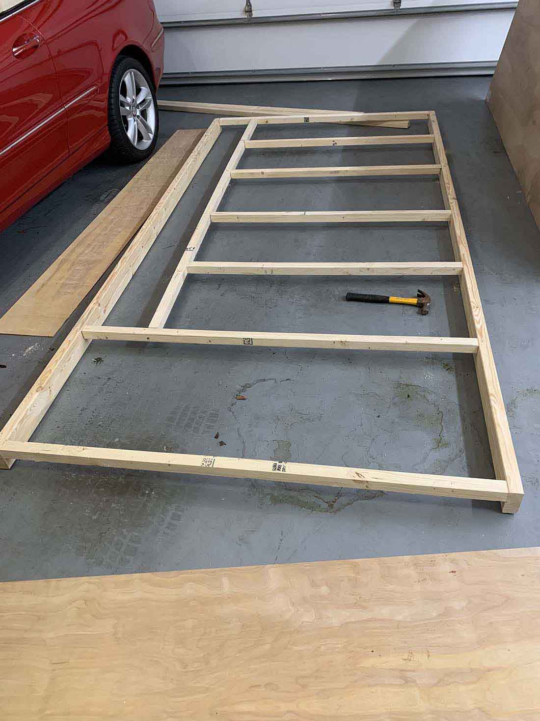
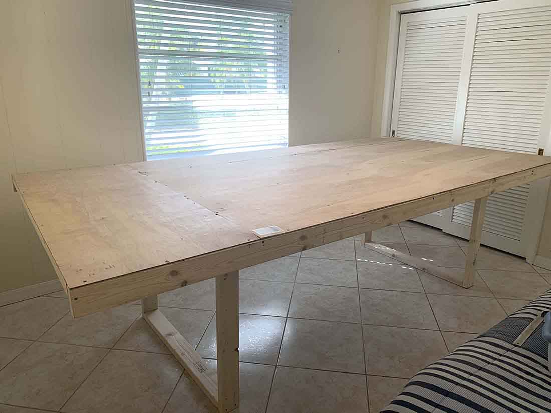
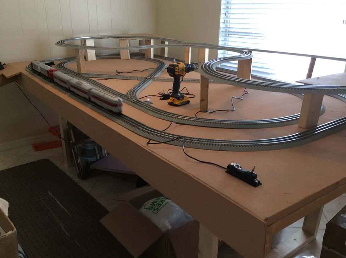
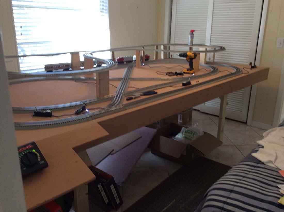
Although Will is a man of few words, I thought I’d post simply because he’s made a start.
Like most things in life, that’s what this hobby is all about – starting.
And it’s the same for wiring… and wiring for DCC layout is something that appears often on the blog.
This leads us to Jeff, who has a small problem with his wiring. Who can help?
“Al, i’ve been reading your blog for the last 2+ years and look forward to it every morning, learning sooo much from others.
I have not contributed before but i now find myself in a bit of a ‘pickle’ and could use some help.
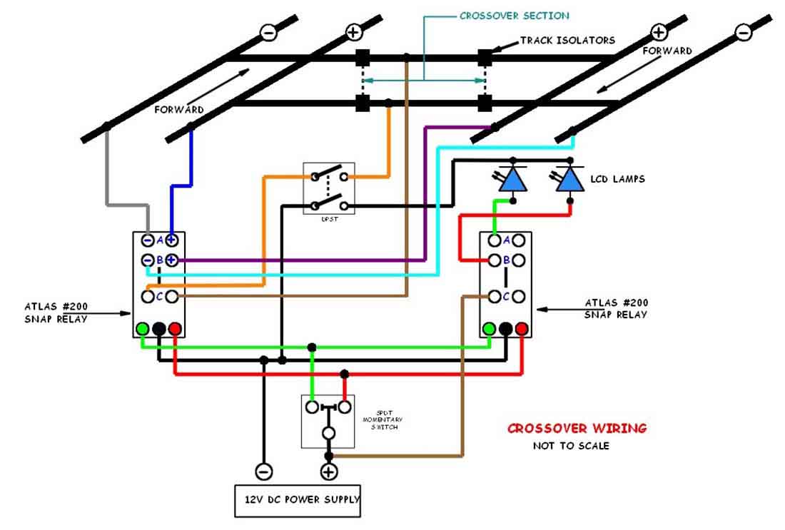
I’m in the process of designing a layout which will have 2 separate sections, a switchyard and mainline, using separate dc cab controls for each. (i’m a bit of an “old schooler”) i would like to incorporate a crossover track joining both sections but by doing so i create a “reversing section” because polarities of each section are in opposite directions.
By using an atlas #200 relay (controlled by a spdt momentary switch), i can direct power to the crossover from either the switchyard cab or mainline cab, knowing that the section i’m entering needs to be set in the opposite direction (forward or reverse) of the section i’m coming from.
I would also like to incorporate a switch that could control power to the crossover section so i can power off the section to eliminate the possibility of accidents. by using a dpst switch (and a 2nd #200 relay), i could also control 2 leds indicating which cab control is powering the crossover.
Can someone assist in either confirming my wiring suspicions or telling me i’m totally wrong and suggesting what i need to do? i’ve included a wiring diagram which i drew to assist in explaining my “problem”. all comments are greatly appreciated.
Jeff “pops”
I’m not sure if Jeff has seen Rob’s post on wiring from yesterday, but anyway, can assist? Please do leave a comment below if you can help with wiring for DCC layout.
That’s all for today folks.
Please do keep ’em coming.
And don’t forget, the Beginner’s Guide is here if you want to stop dreaming and start doing.
Best
Al
Need buildings for your layout? Have a look at the store.
They are great fun to make and great value too.

Jeff & all who might need this kind of help:
1. Produce several copies of your layout on paper in black, on white paper.
2. Trace the positive and negative rails slowly and meticulously by overlaying appropriate contrasting colours. If using polarity switching anywhere enaure EVERY condition is documented. You may have many possible permutations. Any one could reveal a problem.
3. The problem *area(s) should jump out at you before you complete the task !
4. *DON’T ASSUME there is only one problem. Check then address them all. Preferably, more than once.
Sounds like you are doing it correctly. Steps so far seem to be on same legs I would do the most I.portent tho g is to have the same power setting on both transformers not to have it to full power and the intering year in at a slow speed cos when it gets crossed over you stand to derail. Thabks good luck, Mitch
Will, with the space you have you should have went with HO. With all that’s out there why Lionel ? the triple threat train set . ( rail ) I think your second level is a tad high. A fall from there is guaranteed damage.
The Critic
Pretty Kool.!!!!
You need to “sense” when the train enters the area that needs to be reversed. Optical sensors are sold online at reasonable prices. Add to that you would need to do “something” with that sensed condition lo actually switch the polarity of your tracks supply voltage.
Am I missing something, or couldn’t you just permanently alter the track polarity of either the yard or the main line so they matched? Then you could just drive in setting both controllers about the same, or use simple ‘cab control’ switching to power the yard off the main line controller for an arriving or departing train, and switch back to local control to continue shunting the yard.
Jeff,
I believe you need to swap the track power lines on the “A” side of the snap relay. That way when the “A” side is selected the polarity of the isolated track will agree with the the polarity of the “A” track. The direction of the outbound track needs to be changed before the train enters that side of the layout.
What rod said wouldn’t that be the easiest way ,
Reversing the polarity of the track in DC is something to cause head scratching and pencil sucking problems. I had a reversing loop that necessitated use of a double throw double double throw switch. I put signals to stop the train an each end of the loop so I could throw the switch and change polarity. Some one might be able to tell you if it is possible to change polarity without stopping the train.
Andrew in Oz
I agree with Rob M. Use a multimeter to check polarity of tracks
Hi Jeff
Is the crossover isolated section long enough for your longest train? If not you will need to include parts of both the main and yard in your isolated section. You aren’t removing both polarities from the isolated section with the dpst relay which could result in a short circuit when a train enters the isolated section. I would replace the black – wire to the dpst relay with the other power wire and run the black – wire directly to the LEDs. That should do what you want.
Jeff
Change all to same polarity.
Because, one day, you are going to come into the Train-room,
switch-on the power (forgetting Polarity mismatch) and
“POOF”! goodbye layout!
It’s easiest to do it now while it’s still fresh in the memory then
suffer later
Will nice start, Good luck in O-scale check out OGRForum, Think u will enjoy.
Hello
Put a 24v coil 2pole 2c/o relay across A+ & B+ and the 2 outputs, orange & brown go to the relay so if receiving track is not set to Reverse the relay is active and the outputs are disabled. You can set it up so a warning light comes on. You may have a slight problem when the pickup wheels cross the isolator.
You will need resistors in series with the leds otherwise they are one way shotts untilnthey blow
very nice . keep going
This seems an overly complex thing to do, having two dcc controlers. Just seems to go against all the benefits of dcc. WHY ? Our club layout has one system and can have 5 or 6 operators on it without problem, so why have 2 systems, it is bound to cause problems like this, and if something goes wrong who knows what damage could occur to the systems and especially the decoders, all expensive bits of kit.
My advice have a rethink and just use one system but have 2 or more actual controllers. Best of luck, Mike Street
Mike Street, my understanding is that Will said he is old school and running DC, not DCC.
Dwight, what great memories. Love the Canadian Pacific units. Truly a work of art.
Cheers from NZ
Dwight,
I have happy memories of riding the California Zepher, The Cardinal, The Lake Shore, and the Empire Builder trains. I agree that you can’t beat the experience.
Here in the UK the best we can achieve are the overnight trains (when they run) from London to Scotland. We’re not in the same league.
Thanks for triggering happy memories!
Paul
Go to https://wiringfordcc.com/intro2dcc.htm. This website covers DCC in depth. I haven’t looked all the topics over, but I am sure there is a way to wire a crossover so you won’t have to touch a switch. there is a published book, but almost everything is online. There is also a group where you can post questions..