John’s been back in touch with how he solved his crossover problem. Wiring, and clambering around underneath a table is a lot more troublesome as you clock up the years. John has come up with a smart fix though.
(If you want to get up to speed, his last post is here.)
“Good morning (here anyway) Alistair,
The crossover project-
When I first built a model railroad as an adult some 30 years ago, I thought sitting on the floor under the bench-work wiring was fun, kind of a Zen sort of connection to the underworld part of the layout, wiring the roots of that world and all.
Now in my 70’s, the “cosmic roots Zen thing” has left the building, and I’m looking for easier ways to do the “underworld” work, like sitting on a stool in my shop, or on a chair beside the layout.
Only occasional trips to the underground West Virginia Energy Railroad scenery for wire runs back to the control panel, which I normally bribe my grandson to do.
So that’s the back story, and here’s the result.
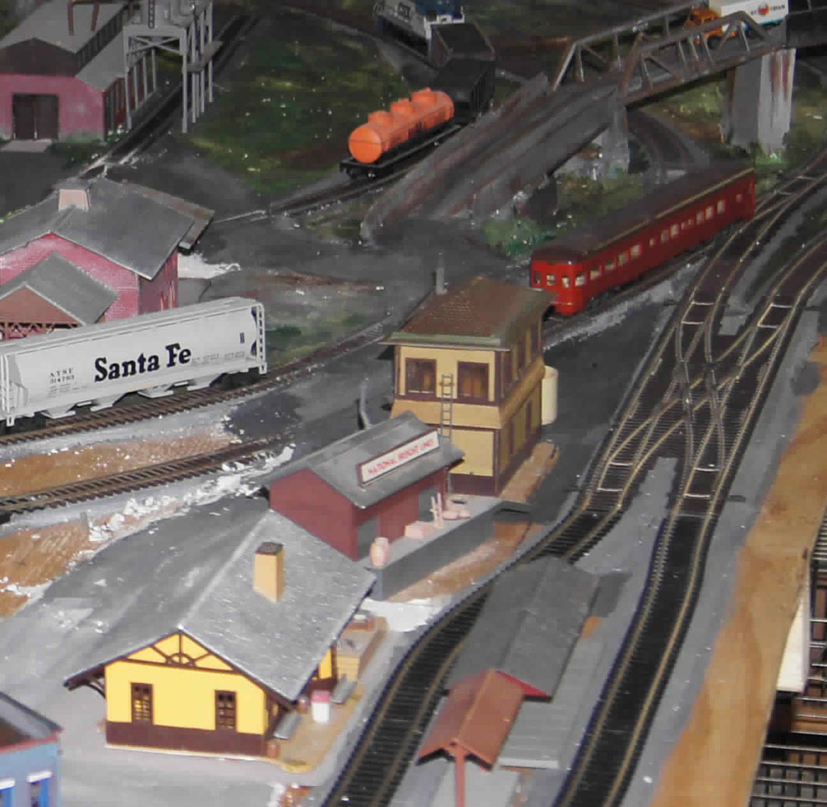
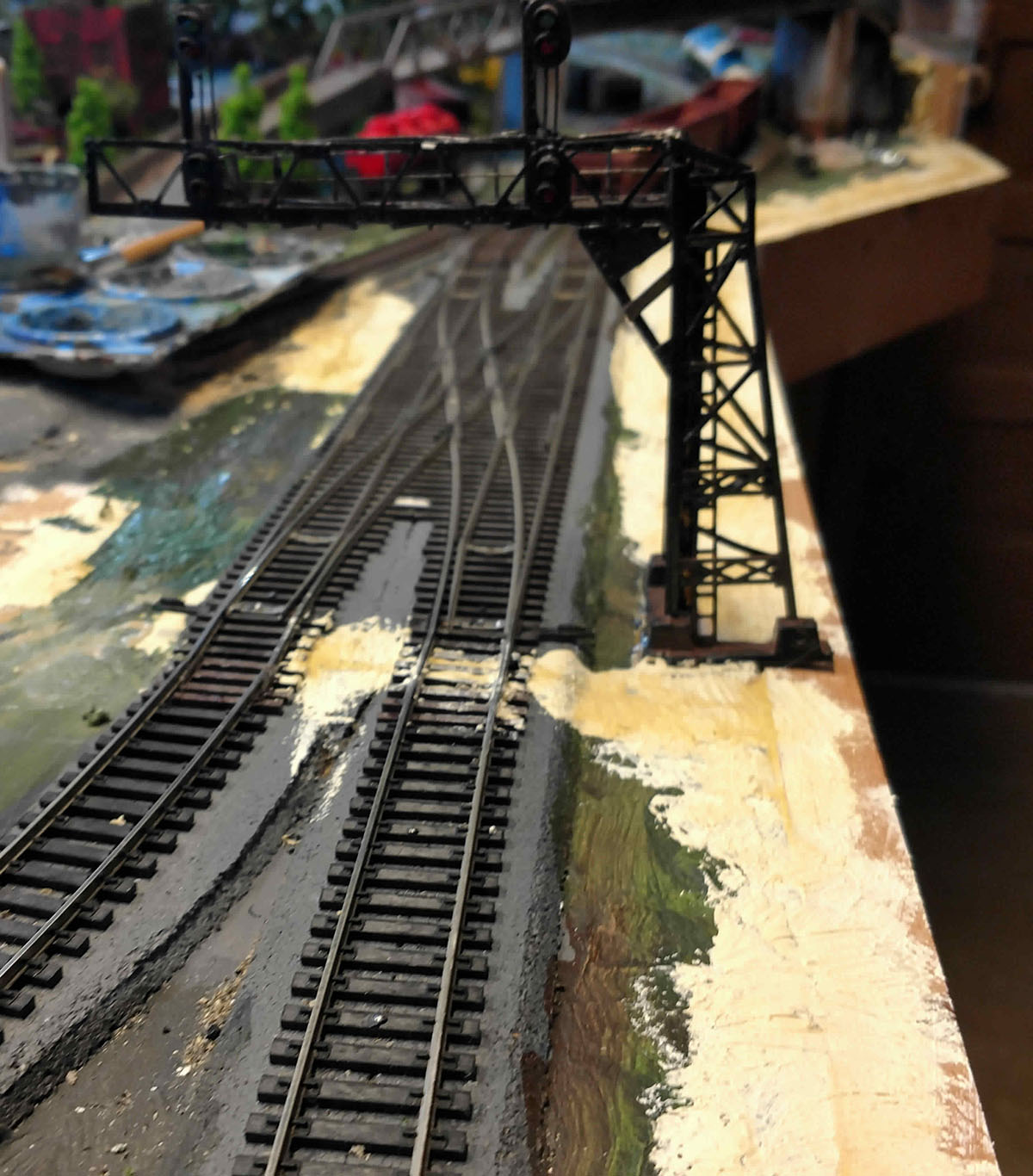
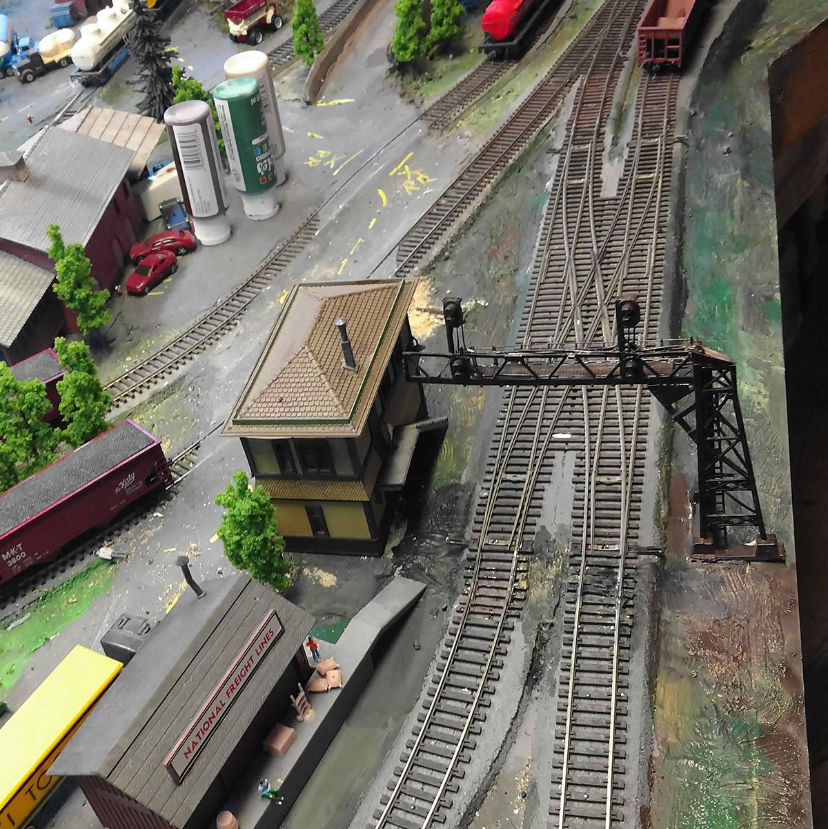
I installed a neat double-crossover some time ago, and operated it by hand while I worked out all the trackwork details and scenery.
It was time to install 4 switch motors and sync them to operate together. I decided that the crossover would operate in 2 states, either both tracks set to go straight through, or both set to crossover. My signals would be display hi-green for straight through, and medium approach for crossover.
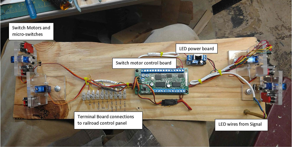
I decided since there was a lot of wiring, and physical mounting of my home-made switch motors, (which were discussed in a previous post) and all the trimming and adjusting the operating rods for the motors to throw the points consistently, it would be easier done on my workbench than over my head from under the layout.
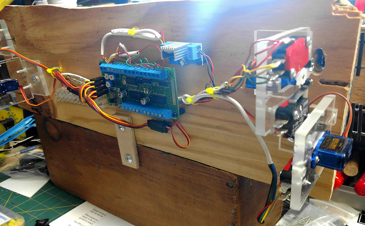
By the way, I purchased from a great company located over in the UK, BLOCK Signalling blocksignalling a servo control board to control the crossover.
I have several circuit boards from them, a reversing loop controller, a points indicator board for snap-type switch machines, and other signal controllers. This company is helpful, has a lot of clever stuff, is quick sending out product, and a good value for the money.
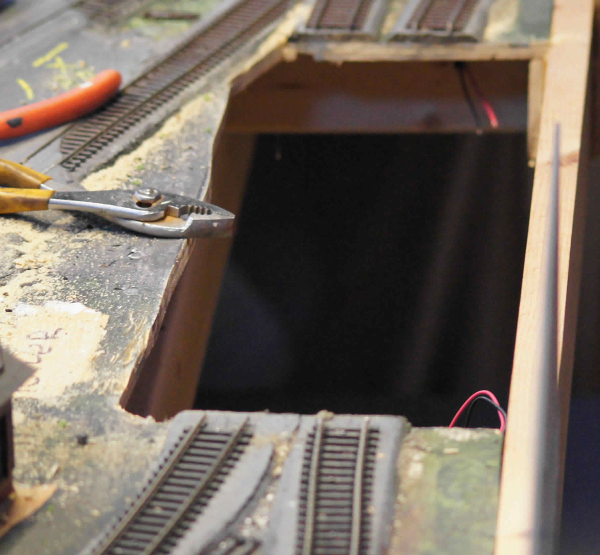
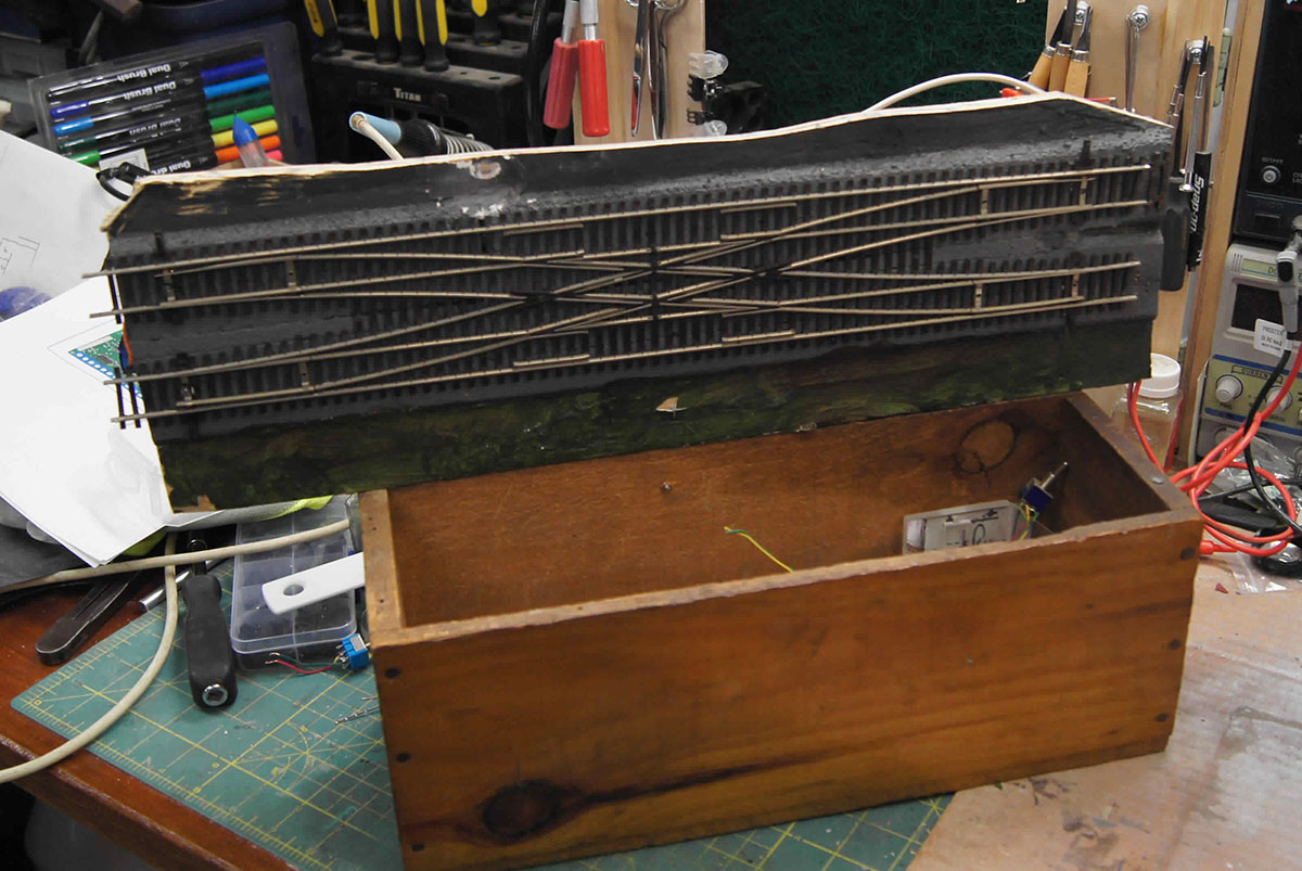
With saber-saw in hand I cut out the crossover. It was an earthquake for cars on the layout, but the buildings came through OK. Anyway, I mounted the section of plywood with the crossover on a wooden box so I could easily get to both sides, then wired up everything, mounted the switch motors, and tested everything a few dozen times.
I decided to use the micro-switches on the switch machines to control the LED green signals.
The red LED’s stay lit all the time as is the policy on some rail systems, this is to assure the signal is working, and is ignored if another signal aspect is lighted, a dark signal is assumed to be out broken, and is taken as a “stop” indication.
I wired in a 12v to 2.5v power supply to run the signal LED’s separate from the servo controller. With everything wired and dressed up it was back to the layout with everything already to go.
I attached a few cleats to assist in replacing the section with the crossover back into the layout. I also previously had the kid run the wiring from the control panel to the location of the crossover so it could be connected before setting the crossover back in the hole in the scenery.
Sitting comfortable on a chair, I made all the track connections and painted the scenery where I had replaced the crossover. Re-connecting the tracks was easily done at the comfortable level of the bench-work, and the trains run better than they did before all the destruction.
I found a great product for scenery repairs, Durham’s rock hard water putty it’s easy to mix in small batches, sets up in 15 minutes, can be easily carved soft for another 15 minutes, then like hard plaster after that, it takes paint well and doesn’t shrink much. In the pictures it shows as yellow.
Enjoy,
John from Baltimore”

A big thanks to John – it’s wonderful to see how all tackle your issues and come up with so many solutions.
I think that’s one of the fun parts of this hobby, there are a million and one different ways of solving a problem.
That’s all for this time folks.
Please do keep ’em coming.
And if today is the day you stop dreaming, and start doing, don’t forget the Beginner’s Guide is here.
Best
Al
PS Latest ebay cheat sheet is here. Still going strong and goes mad this time of year.


John, good idea and a very neat finish – did you stick labels on just in case you forget in the future?
Can confirm that Block Signalling customer help is excellent.
Well I’m impressed that’s given me an idea I’ve a few motors to add to the layout
Very impressive. Brilliant.
Looks like the points are not set correctly on the upper right turnout…
John, that is a unique idea for easy wiring of the double crossover. I am going to offer a slightly different option. what you do is make cranks, little 0.030 wire formed with 1/8″ above and about 1.5″ below the layout. This crank provides substantial pressure to operate a switch. You line up the cranks on a centerline from all four switches and then connect them with an ordinary straw. Then a single switch machine, I use tortoise to operates all four at once. Now using 12 volts, I install dual LEDs with red/grn colors in series with the switch so that a single wire controls the entire crossover and the LEDs show set directon. Your wiring is complicated, but need not be. Using this wiring can substantially simplify underneath wiring. Good Luck, Bob
Bob, any chance you could post a picture or drawing?
great idea–just cut a section out, and sit at your work bench to install all electronics my knees and back love the idea!
Great, I’m from Baltimore also, contact me
John,
Super stuff mate – thank you.
Would you have time to send me the name and contact in the UK for the blocksignalling and other stuff that you purchased from over there.
I am working on a new model train layout over here in the USa (northern Indiana) but I am a Brit and we move backwards & forwards between the UK and USA.
Any help would be greatly appreciated.
All the best,
John
I installed a similar ‘cross-over’ last year. When I built my HO layout, I set the parallel ‘main lines’ 2 ½” apart so I could not use a pre-made crossover. I used 4 turnouts and it took up a total of 30″ in length.
I did not have to cut a big hole in the layout. I took up the existing track that had been ballasted and because I did not glue the track down, only used nails, I did no damage to the Woodland Scenics foam roadbed.
I pre-fit and cut the rails on the workbench and installed the turnouts one at a time. I used 4 Tortoise motors wired so the appropriate turnouts move together. I used the built in SPDT switches to power the frogs and indicator LEDs on my control panel.
When I look at all the work and electronics that John used, I’m glad I went ‘old school DC’.
My total cost: $80.00 for the #5 M.E. “ladder” turnouts (2 RH and 2 LH), and $60.00 for the Tortoise motors. Everything else I had on hand.
Al & John from Baltimore……. Thanks for this great article on block signaling and the crossover setups. I have two double crossovers on my mainline that I have been planning to add block signaling. The switches are working well but I am going to change the switch machines to under table switch machines and add block signaling that will work in concert with the switch positions. I am also going to control the power to the blocks on the main lines when there is going to be a crossover. Your article is a great help. I am going to contact the blocksignaling company in the UK and give them my plans and have them recommend the circuitry that I should be using. Thank you.
Hi All
I read this interesting posts. On this last one for what he ended up using, he could have used a “arduino micro controller”. Looking at his pics he has servos activating micro switches which is all good but that all could have been eliminated by just using sensors
Regards
Frank
Neat layout.!!!
Brilliant!
Hi John
Its anther John here! Like you I am in my seventies, and like you I much prefer wiring on the bench. I’m making may first serious layout since I was a teenager and I have designed the construction to allow me to do most wiring on the table.
My layout table (its on three levels) is made from wooden frames with light plywood tops and I only have easy(??) access to the bottom layer.
To get round this, I have loose laid the plywood tops on the frame with the tracks on them, also loose laid. I have then marked everything out, made the necessary drillings and then lifted the track and the board and taken it to the work table. I am now in the process of wiring my third board out of six. Each one has either a single 25 pin plug to the control panel or flying leads to connect to adjacent boards.
Much easier than lying / half sitting, squinting at things I can’t see with my varifocals and having hot solder dripping on me!
Happy modelling. Happy new year, and stay safe.
John
Sounds like John also found a great kid to do the wiring. Got to be smarter than I am. Hope I can find one of them. I am getting ready to start on my first n scale project. Hope it takes me less than 6 years. After that somebody else may have to enjoy it.
In a previous response I neglected to say that your (John’s) project looks great. I can only hope that my new start can look half as good.
Great ideas on a beautiful layout. I may try it one day myself. A suggestion and a warning. The cleat for realigning the cutout to the layout is brilliant, but I would suggest 4 screws instead of 2. If in the future, if you need to work on that section again, 4 screws insures stability whereas 2 are subject to vibration and mis-alignment. In your case, not much risk but using the concept for other parts of a layout and cutouts could present a problem.
P.S. I would also like to see pics of Bob Schildgen’s setup for the same crossover. I’ve used paper clips with under the table switch machines with great success; and very inexpensive and simple to fashion where needed.
Very nice, John. I especially enjoyed the “sinkhole” when you saber-sawed out the switch section…looked like the aliens attacked and took it up in their ship! (which is what actually happened, huh?) 😉
Might I suggest the purchase of a multitool for your next surgery. Much smoother for this sort of dissection. Maybe turn that 6.5 on the Richter scale into a 2.7. I bought one about a year ago and love it!
I would be interested to see the wiring and mechanical solution that Bob Schildgen described in a post!
The block signalling link did not work for me got: FORBIDDEN, you do not have permission to access this site?
Disappointing since we are so far behind you on this side of the pond in the use of servos for turnout (points ?) motors.
Are you using DC or DCC on the layout(s), or are the turnouts and signals wired separately from track power? How would a double slip switch be wired and controlled? Seems a waste to only use it as a double crossover,