Lawrence has been back in touch with his O scale lift bridge:
“Hi Al
I am starting a new section of my layout.
I have two O scale, one N scale and numerous HO scale Engines. My concept is to build the O scale lift bridge at a height of 22 inches. And put the HO and N at a height of 39 inches (where it will connect with my Lincoln Nebraska rail yard).
All wiring will come out to the edge of the layout and run in a designated wire run tube, nothing underneath. I am presently working on the lower level at the present.
I plan on two separate loops with a run of 30 feet between the ends, 24 inches wide on the long runs. This means that the long run will have four tracks side by side, I decided not to have a cross over between the ends. After watching many utube videos on lift bridges I decided I wanted one of them for access purposes. The lift bridge is what this is about.
After looking at many bridge designs on the web I decided on one. Then by measuring the height of the tallest item, on a track, I figured out the height required for the bridge framework.
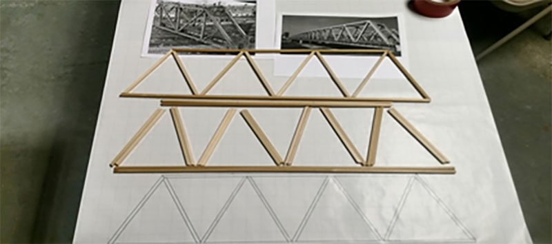
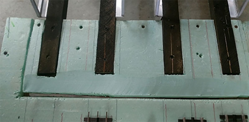
The first picture displays the type of bridge and the design drawing. The drawing is made to the actual size required for the structure.
I did a similar sequence for the top of the structure. I used regular wood glue to attach the pieces. Then it was easy to size and cut the square balsa wood, from Michael’s. With four tracks, I wanted two bridges each covering two tracks.
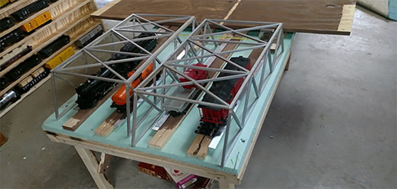
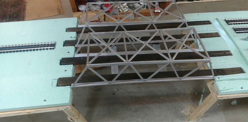
Then build the structures and brush painted them with acrylic silver paint. Just for a check I put the two on the layout with the tallest items underneath. My initial idea was to make the top ten inches wide. Doing the measurements, I decided it was too wide. I tore the structure apart and made it eight inches wide. This turned out to be the correct size for train spacing and layout structure.
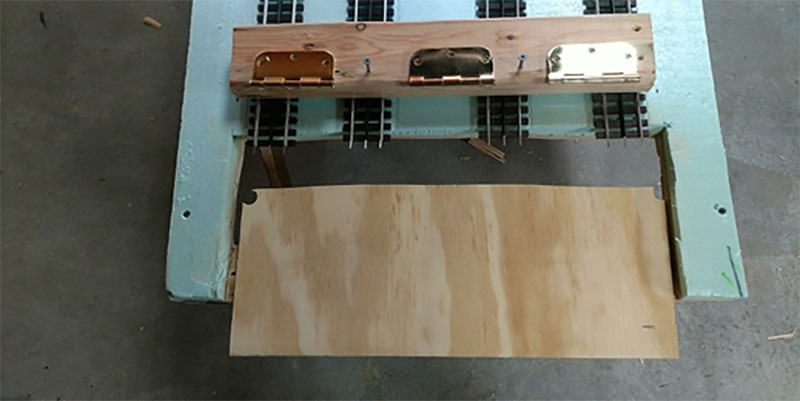
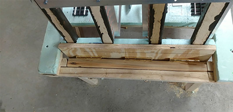
The next picture shows where the layout has been cut out. I decided on three hinges to help ensure no rotation of the bridge in the future from usage. The upper board in the picture has been beveled so the hinges are perfectly level with the top of the board.
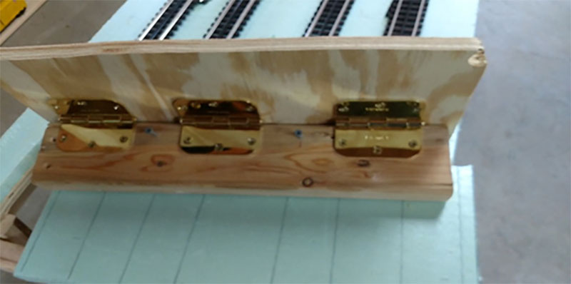
The next picture shows the track base board connected to the brace board. The brace board is needed as a back stop for the rotation of the bridge. The layout is built with 2×2’s and a 2×2 is used for the legs as part of the leg is displayed in the picture.
The brace board is a 2×4 so it sets it back from the layout frame. But it is also the width of the track base board so when installed it comes out to the edge of the layout and leaves a space at the back for clearance when the bridge is lifted as shown later.
The next picture the rotator section is installed (hopefully the only time I will have to lay flat on the floor) and the foam put in place. The foam on the rotating section needs to be cut back for rotating clearance. The track foundation boards are installed with the bridge side pieces and for alignment. Had trouble with the height of the foam at this point causing the layout track and the bridge track having a height differential of one eight of an inch. Replaced the one-inch foam with ¾ inch foam and problem corrected (not shown in the last picture).
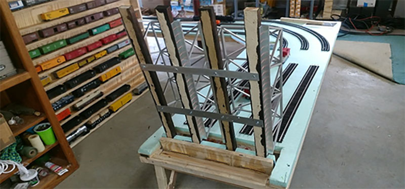
The next picture shows the bridge structure attached to the track base boards. Also attached is two aluminum cross pieces to help ensure the bridge is lifted as one unit and there is no rotation of the tracks with each other. But of course, the cross pieces are the walkway between tracks for the workers.
The far end of the bridge layout is cut out of the foam so the bridge lays flat. Had a slight problem here as the near end board would not lay flat. As it turned out by carful adjustment of the screws, at the right of the picture, the problem was corrected.
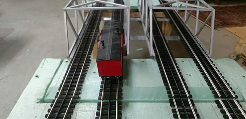
Final testing. The next two pictures show the lift bridge working as it should. This gives me a two-foot access. The picture shows a close up of the rotating section. Also note that the bridge framework does not impact the layout.
The last picture displays the track in place with the tallest and widest O scale item I own. Plenty of height spacing available and enough width spacing. This bridge is 2 feet long. The next problem way in the future is building the bridge for the upper layout at 39 inches. Might have to make that lift bridge 3 feet long.
Final note, nothing I perfect. The height of the track of the layout comes out to be 1/32 of an inch lower than the track on the bridge. Because of the bridge rotation no joiners at either end can be used. Lifting the layout track to match the bridge is just a minor problem.
The wiring of the bridge track will be the only under track wiring between the bridge and the layout. But with the bridge lifted I can sit in a chair next to it and wire it up with a rotation loop at the layout end.
I hope this has been helpful for anyone willing to take on this enterprise. It was a real learning experience for me.
Lawrence”
A huge thanks to Lawrence for sharing his O scale lift bridge- it’s a real pleasure to see the pics and the progress of a project like this. I do find myself reading them again and again. Clever stuff.
That’s all for today folks.
Please do keep ’em coming.
And don’t forget, if today’s the day you start on your very own journey, the Beginner’s Guide is here.
Best
Al
PS Latest ebay cheat sheet is here.


First class job with that project Laurence , not the easiest of builds , but you look to have done a great job there …Dangerous Dave
Looks good, useful and well documented.
Great looking bridge. seems to work well.
I was considering doing something like this, but yours is a better idea. The hinge system you made fixes all the issues I would need to work out. Now, I’ll use your type of hinge placement and save myself the head-scratching.
Well done. Thanks for sharing.
Great work, I am thinking of a swing bridge to gap to access inside the layout.
Yours, give me inspiration, I am in O gauge(Lionel) since 1948..
As a ”young man”, I accept all positive hints. Thank you Lawrence.
Léo .
Québec, Can.
Looks great, practical and with great instructions.!!!
Just a side note, I used piano hinges for a project like this in the past, and yes the alignment is still an issue. Great work!!
I’ve never attempted a project like this so I’m just thinking out loud. What if you used euro style cabinet hinges that allow 3-dimensional adjustments like they use on kitchen cabinet doors? Wouldn’t that give you much more control over the connection between the bridge and the rest of the layout? Just asking …
Hello,
I fyou had problem with de hinches dan you must yuse piano hiches dat always correct and no diverens between de rotation.
Regards,
HC Treintje Belgium (Herman).
Hi, The only issue I have is the wiring. I am not sure what you meant by tube run? How is the connection from the end of the lift out to the other end? This would allow the circuit to be cut when the lift out is in the up position. How did you wire it to the other end (non lift out)?
Thank you so much . PS My lift out is about four feet long
Try a piano hinge for the hinge. It is one piece and can be cut to exact length.
Your bridge will never go out of alignment.
Lawrence,
I am a retired Locomotive Engineer and I worked for the BNSF and ran out of Lincoln Nebraska for almost 40 years. You have a very nice layout!! I am trying to get started on a combination layout with O, O27, HO, and N. Maybe too ambitious.
I was wondering if you had any Pics of your Lincoln Yard setup?
Thanks,
Tim
Lincoln, Ne.
Lawrence
IMHO your bridge design should work OK with O scale where track tolerances wont be as critical as with smaller scales. The landing section should have alignment pins to assure dead on track alignment each time you close the bridge. Just like the real ones.
I cant wait for you to put the whole concept together to check out the perspectives with the 3 scales. Many pundits said dont mix scales but I disagree and if you do it right it should be awesome. Please keep us posted.
Gidday Lawrence
Put contact plates UNDER the track on the bridge, and on the TOP of the base
plate. When you close the bridge, contacts are ‘MADE’ and you’re in business
Good Job! I’ve been procrastinating on building my own bridge. Thank you for posting. I may try your solution.