Arnie has been in touch again. Here’s what he wrote:
“Jim, Nice work. Looks like your N layout is progressing nicely.
And Dave — many thanks to you for taking the time to create a How-To video on lighting.
I’ve gotten a number of requests on this topic but have not had an opportunity to make a How-To video.
I all too often jump into my projects only to realize later that a How-To on my lighting (and other things) would have been helpful to others. So thanks again.
SOME ADDITIONAL TIPS:
By the way, pay heed to Dave’s comments and reiterations of using regulated power. Using multi-voltage power supplies is a safe bet.
But if you don’t have such power supplies available, be sure to use resistors to help ensure the voltage capacity of bulbs and LEDs is not surpassed!
If your lighting items do not come with resistors, you can check online for info on how to calculate what capacity resistor you should be using with your light source.
I’ve found that resistor values of ~620 ohms to 910 ohms @ 1/4 watt work well with 3 volt DC or AC/DC light sources depending on how bright you want them to shine: The greater the resistance (ohms), the less bright they will shine. With LEDs, the resistor is usually connected to the positive lead.
Also, solder your connected leads to avoid separation if accidental tugging on the wires should occur.
And as Dave points out, use heat shrink tubing whenever you can to insulate your leads to avoid electrical shorts.
It’s neat and better than using electrical insulating tape which is very hard to wrap around thin wiring.
Instead of using a standard heat gun (because they generate great heat and you can easily burn yourself), I prefer to use an ‘electric’ match. These are the items that work like a cigarette lighter and are great, for example, for re-iginiting a gas pilot light that’s out on a hot water heater, charcoal on a BBQ grill, etc.
You just click and a small flame is generated that you touch to and run along the heat shrink tubing for a couple of seconds till it shrinks.
Also, after many, many hours of running hundreds of feet of wire under my N scale SV&GS layout, I found an easier way to do the soldering and heat shrink insulating.
I take a measurement from under the layout of the length of wire a hook up will need : from power source and/or power terminal strips to the lighted item.
Then allow at least 4 additional inches at each end of the wire for wire stripping, soldering and general slack for ease of movement.
Then OFF the layout, solder the wire to the leads of the light item and add the heat shrink tubing. It’s much easier than trying to do these things under a layout (especially in N gauge and with very fine wiring).
Then take the item and run the finished wires from above the layout down and to the power supply or junction terminals below the layout.
And one last thing I always do is make multiple copies of a label identifying the item and place them on/along the wire run. So if you have to trace the line on a problematic item at some point, it will be easier to do so.
Arnie”
“Hi Al,
Here are some photos, of my Hornby 0-4-0st pug number 51240, and Hornby railroad Jinty 0-6-0 S&DJR number 24 after I fitted a light bulb in the cabs to give a glowing fire box effect.
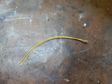
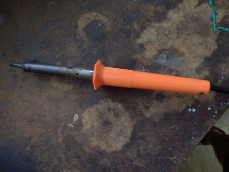
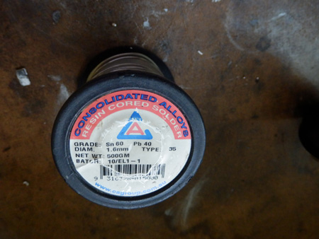
The tools and materials required are a light bulbs 12 volt, I purchased mine from Jay car, a soldering iron, solder, and a drill.
With the pug I unclipped the cab as that gives access the motor, and with the light bulb, it had leads already to it, I trimmed the leads, so that the bulb can sit in the middle of the cab. I then soldered the light bulb on to the contacts on top of the motor.
With the Jinty the work was more involved, I removed the body from the chassis, then drilled a hole through the backhead to where the firebox would normally be, I trimmed the leads again and .again soldered the lightbulb onto the contacts on top of the motor. After trimming the leads the ends of the wire leads have to be bared for this to work, this is done before soldering.
Paul”
A big thanks to Arnie and Paul.
Don’t forgot to have a quick look-see at the latest ‘ebay cheat sheet‘.
That’s all for today folks.
Please do keep ’em coming.
And if today is the day you get started on your layout, the Beginner’s Guide is here.
Best
Al

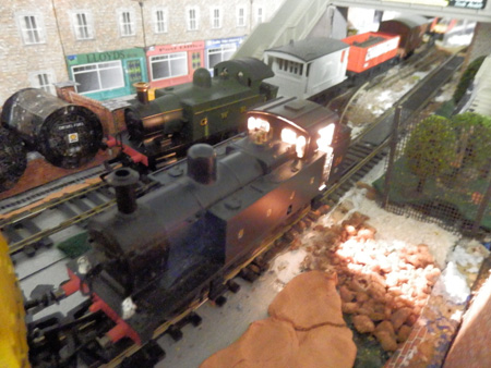
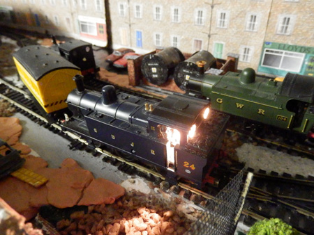


The lighting in the cab of the steam loco is so bright it looks like the cab is on fire, good job though and maybe a resistor to tone it down a bit.
Re the light bulb in the firebox. It is a good idea to “aquire” your partner’s red nail varnish and coat the bulb with this. It makes the glow a lot more RED than white and also reduces the brightness, which I find gives a more realistic effect.
Thanks for all the tips.
By the way when soldering brass and avoiding solder spread draw a line with a pencil on the visible side of the joint. Solder from the other side and create a good fillet. The solder will run as far as the pencil line and then stop. Result – a clean but strong joint
Do you need that bright a bulb in the locomotive’s cab.
Isn’t suppose to be a light from the engine’s firebox?
Is there a proper way to install a resistor? An “in” and an “out” so to speak? The color lines give information, do they also say which end goes towards the source and whch end goes towards the load?
Really like your helpful notes on all subjects.
Great job with the firebox light,but a good idea from Nigel to tone it down with nail varnish.Keep them coming.
Don,
Unlike diodes, which work differently depending on how you hook up the DC current to them, most resistors are not polarized – so it usually doesn’t matter which way you connect the wires to them. For consistence of appearance only, I prefer to connect resistors with the value markings on the + side and the unmarked end to the – side. This way I can tell at a quick glance the polarity of the wires feeding them. This visual identification shortcut only works if you are consistent with your connections, however. Diodes work differently – connected one way they block the current, and connected the other way they allow it to pass. Keep us posted as to your progress. Best wishes.
You should see the effect at night.
I love this idea
Rand
No, resistors are not polarized, they can be put in your series or parallel circuits in either direction. Use them in series with your lamps to one of the lamp or led wire. The lower the resistance value the more current thru the led or bulb, hence a brighter light, but bear in mind that if you go too low in value, both the lamp and the resistor can get warm. A 10 ohm resistor in a 12V circuit will draw 1.2 amps and produce 14.4 watts of power, hardly what a 1/2 watt resistor will stand up to and it will get very hot and most likely catch fire, burning a hole in your prized loco.
Stay with a minimum of a 470 ohm resistor (common size) that would draw @ 25 milliamps and produce .3 watts in a 12V circuit, which is below the ½ watt rating of a ½ watt resistor.
Quite right about resistors being non polarised, but it does make sense to put them in so you can read the rings left to right (Cloe together ones go to the left) Pos. to Neg. idea is really good.
The lighting projects are very impressive, I must try some, maybe a sign for starters.
With the glowing firebox, does anyone remember the Triang Hornby model of the Flying Scotsman?, that had a light bulb, which did give the same effect.
That model was a coarse model, but was ahead of its time as regarding special effects. I was given the job of restoring an old Triang model of the Scotsman, and when I got it running, I liked it so much that I purchased a new Hornby model of it. I was trying to recreate with Hornby railroad models the same effect.
Thanks all for the information on lighting … this is one of the areas I lack knowledge in. Your input here has helped me out. thanks again
regards
Tom N
BEAUTIFUL LIGHTING.
I use led’s all over my “N” scale layout. The resistor must be connected to the anode side of the led. I use a 330 ohm 1/4 watt resistor connected to each led. I power the led’s with a 5 volt DC power supply. There is no polarity on a resistor. The color code for a 330 ohm resistor is orange, orange, brown. The fourth color is the tolerance band. A silver band is 20% A gold band is 5% tolerance. Hope this helps.
Bill
CLOSE THE FIRBOX DOOR THE FIRE IS WAY TO HOT !!!!!!!!!!
I’m really interested in all lighting tips as this is something I’m trying to get to grips with in the near future, thanks for these. wonderful idea having it in the train
very nice job off work guys, However as previously stated, Its a tad too bright , Put a resistor inline or try painting the bulb with orange or red paint laquer, clear red or orange, repeat until the correct colour is achieved, Then you will have the right effect and can be repeated on other engines in your collection, You can buy orange LED’s that flicker fast and that are pre-wired with resistor already, just solder in and replace the hot bulb, that will really improve your model also by using the LED, it reduces the voltage used so no or little power is lost from engine motor ! , But on the whole guys, Good job ……
Sid
Makes think the engineer and fireman are heating a pot of tea. Beautiful work.
I though this was realy neet the way it was done
Al are you still on internet?
I’ve used 12V 80ma (.080 amps) grain of wheat bulbs. I also use 12V regulated power supplies as Dave so admittedly voiced. I use laptop brick supplies easily purchased on E-bay for about $10.00 US. Be sure to add a fuse at the supply so you don’t burn things up in the event of a short circuit on the layout.
Instead of purchasing many power regulator supplies for gain of wheat or rice light for layout lighting, you can purchase Radio Shack a power step down transformer input of 120 volt AC, output 6.3 Volt DC with terminal strips and wire all lighting in one area. I install switches for different areas.
Don’t understand all that ohms, amps stuff. Waiting with baited breath for Woodland Scenics new Just Plug lighting system. Even a dumb dame like me can light up the scene. But love the effects you electrical guys do. Gorgeous.
Poor engineer in that loco, he has to be blinded!!!!! Fry`s electronics sells a power supply that has outputs of 3-4.5-6-7-5.9-12volts DC turn the knob to your choose it has 2amp regulated output. The brand is Philmore Model no. MW122A. They work great cost about $27.00. You can change how bright your lights are just by turning the rotary selector. I have 2 layouts and use several of these. Good Luck Tom in AZ
Well I am not sure if this would work to tone lights down,however as a plastic modeler,they have both red and amber translucent paint for doing model car taillights and side markerlights.I don;t imagine they would get hot enough to ignite the paint after they have dried.I would want to test that to be certain before putting alot of work into it.But would seem an easy fix to me
“Re the light bulb in the firebox. It is a good idea to “acquire” your partner’s red nail varnish and coat the bulb with this.”
Well…..Maybe not….
Once upon a time during a well attended ‘Train Show’, the Lionel operating crane quickly became the center of attention on one of the layouts. Seems the previous owner had done the same thing! Painted a tint with nail polish on an otherwise clear light bulb. The almost constant operation of the crane during the show caused the bulb to get VERY warm resulting in the only SMOKING CRANE at the event! Might be OK in the previous post as IT IS a stem engine. My older HO gauge steamers use a flat, rectangular LED beneath or inside the firebox to visually enhance their operation. A small full wave bridge rectifier is mounted inside the shell enabling the 1 1/2 V headlight to glow brightly anytime the power is applied to the track. A similar one is placed with a diode for the rear tender light. No more flickering or variance of illumination. Just wire the rectifier in backwards to achieve a constant voltage to the lighting system. +&- leads to the track voltage and attach the light bulb leads to the AC posts. GREAT for lighting passenger cars!
LEDs usually don’t get hot only the resistor does. They are cool little things.
I’m with Babs. Have no clue when it comes to electrical terms or equipment. Need step by step instruction if possible. Considering plug and play but keep up the good work and suggestions. I look forward to the daily e-mail and tips. It’s a great site with many great ideas. Hope to start my first HO layout soon. Thanks again for all the tips/suggestions.
Hi Al – and thanks once again for the re-posting of another of my earlier tips for the modelers. Be well — Arnie Steiner, Staten Island, NY
Arnie, Thanks for the great wiring tips. Any idea that reduces the amount of time I have to spend underneath the layout is always welcome! And thanks again for all your previous postings of your Susquehanna Valley & Gulf Summit layout. I’ve enjoyed every one of them.
outstanding pic of the cab looks like a superlight in there