Jeff’s been in touch with how to build model railroad incline:
“Al.
First off, I would like to thank you for your hard work to keep this site going. I’m quite sure it’s a tedious (but rewarding) job.
This is not my first submission and thought this may inspire others to get some of their creative juices flowing.
Like many of the readers of your blog, I am now retired and on a fixed income. So, when I decided to put together a new HO layout, construction cost was very important.
I went to work designing the new layout, using the AnyRail program to aid my design.
It will consist of a twice-around mainline surrounding a switching yard and spurs for a rock quarry, a fueling facility and engine shed, and small warehouse loading/unloading docks. (My grandkids love to watch the “choo-choos” go roundy-round and I like to play in the switch yard.)
In design, the mainline will cross over parts of the switch yard and a lake area. In doing so, the tracks will need to rise and drop about 3 inches from the main level of the yard.
To make this incline/decline I considered purchasing the Woodland Scenic kit they provide. As stated earlier, the costs of such a produce is a bit overwhelming so I thought I might try making my own.
A local stone mason working in the area was kind enough to supply me with some 2 inch pink rigid insulation which they used to separate their stones on the pallets delivered to the jobsite. Therefore, I have a surplus of larger pieces to work with.
After much experimentation I finally came up with a design which was not too hard to make after initial setup. This is how I went about the process…
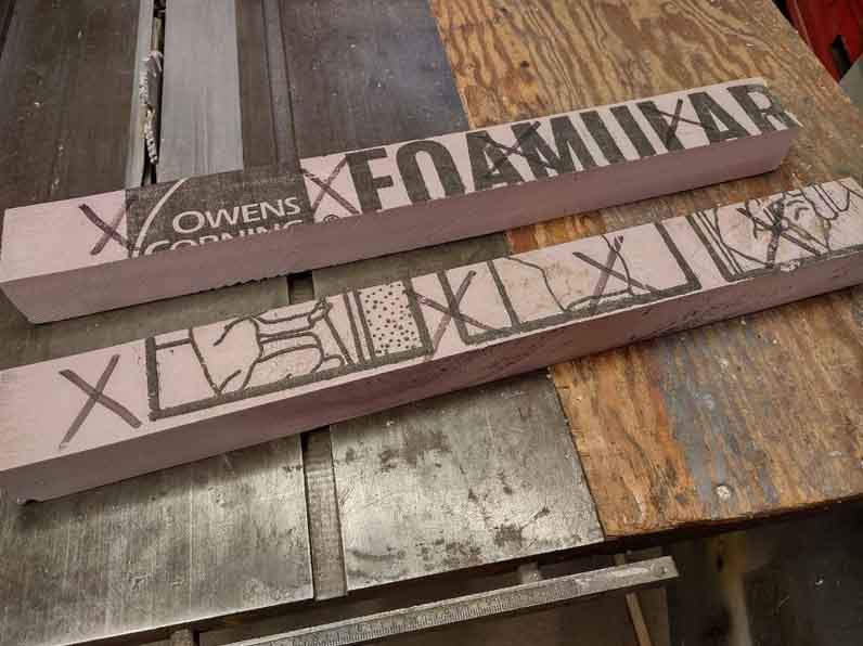
First, using my table saw, I cut the insulation sheets into workable sizes.
In my case, I’m working in HO scale, so the pieces I cut would be 24” long and 2 ½” wide.
Anything greater than 2” I laminated two pieces together with construction adhesive, allowing them to cure for about 24 hours.
You’ll also notice in the photo I marked one of the 2 ½” sides with an “X” as this would serve as the bottom edge of the incline piece.
I made sure when cutting, the “X” edge was always against the fence.
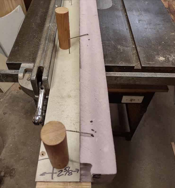
Next, I went about making a taper jig for cutting the angle of rise/fall in each piece. I wanted a 2% grade, so my taper jig was 24” long and ½” larger on one end than the other.
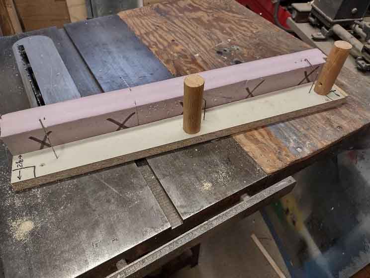
Placing the “X” side against the taper jig, I cut the taper into the foam. (PLEASE BE VERY CAREFUL WITH THIS PROCESS SINCE THE SAW BLADE NEEDS TO BE SO HIGH.)
I might also suggest devising some way to hold the piece against the jig to eliminate the possibility of an accident. Kinda hard to work on your railroad with fewer fingers!
You can also use some of the cut off pieces for the thinner taper strips. Some of my pieces would be used as “riser” pieces so no taper was cut.
How to build model railroad incline:
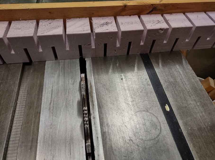
In order to get the rigid foam to conform to the curves of the track, I needed to devise a way to make this happen. With my woodworking capabilities, I made a jig for the saw which would create “kerfs” in the foam board to allow it to bend without breaking.
Again, after much trial and error I finally decided on the right pattern I needed. In my case, the kerfs are ¼” wide, 1 ¼” deep and 2” on center.
This pattern will allow the foam to follow a minimum radius of at least 18”.
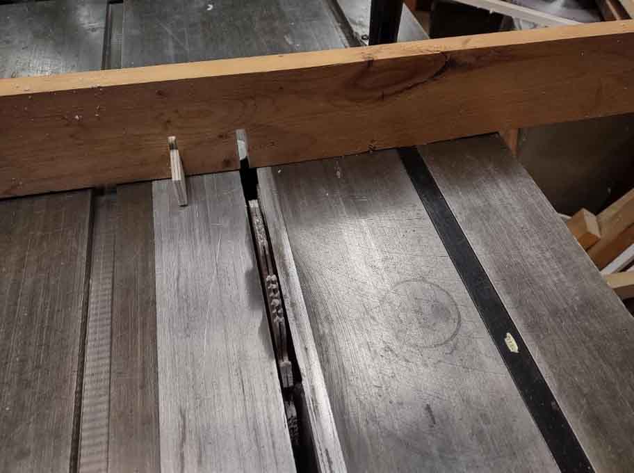
Using my newly created jig, I went about cutting the kerfs in each piece of foam board, cutting one side first, then flipping the piece end for end and cutting the other side, making sure the “X” side was still against the jig. I needed to make sure the kerfs on the opposite side were halfway between the first side, so proper the measurements were taken.
All said and done, I now had multiple pieces which would become my incline/decline ramps and risers. The last step before installing would be marking a center line on what would be the top edge for ease of installation of roadbed and track.
Aside from the time spent (of which I have plenty, being retired), I figured I saved about $100 u.s. which can now go toward different aspects of my model railroading project.
I have yet to install any of these pieces because my layout base is not yet ready.
I hope this has been somewhat informative to others. I tried to explain as best I could without confusing everyone.
Thanks again for all you do for our railroading community.
Jeff (Pops) Somerfield
Chicago, USA”
A big thanks to Jeff for his take on how to build model railroad incline. What a clever lot you are.
It reminded me of Paul’s post: HO scale track risers
And if today is the day you poke boredom in the eye and join in the fun, the Beginner’s Guide is here.
That’s all for today folks.
Please do keep ’em coming.
Best
Al
PS More HO scale train layouts here if that’s your thing.
Need buildings for your layout? Have a look at the Silly Discount bundle.

Jeff, Very clever with the table saw to make the flexible foam risers. I have used foam risers on my layout Farland since the beginning. One thing I did learn the hard way when using foam risers for inclines is if there is any unevenness under it, that uneven point will be transmitted up to the track. When that happens, your train will see a sudden increase in incline, and even though it is for a short duration, the engine can stall and slip at that point. Just another of those funny things that can happen. best of luck with your foam. In fact, I can do better than that, best of luck with your layout. Rob McCrain – Farland Howe
Hey Pops, awesome “How to” tutorial. I am exactly at the same stage as you are with my HO benchmark. I work for California Closets as a carpenter and know my way around a table saw and woodshed. However, I had a much more complicated and costly way of putting my outer 2 rails up…and then I saw your tutorial. Easier, faster, and much less costly. My initial plans were to mount a wall shelf, 6 ¼” deep, around 3 walls of the room, with the highest point being 14″ and tapering down with a 3% grade to ground level. I have plenty of foam board to do this already. It’s always a pleasure to see one’s finished train layouts, here. But it’s always a treat to see and read, the “How to’s” as well. I look forward to seeing your completed layout, here, one day. Thanks again, Pops!!!
Pops
Well done-Thanks. Add that a good mask should be worn during cutting & clean-up. You must not breathe any of that pink dust.
To Rob McCrain: don’t tease us talking about your layout … SEND OICTURES” … share your experiance!!!
Thanks
Great how to info. I actually used that very same procedure several years ago and I also was pleased with the outcome. Great minds…..
A great do it yourself post! Very creative thinking Pops !!
How are you attaching the track to the foam. I would think that nails wouldn’t hold
To David Marlin: You must be new or haven’t been paying attention, Rob share his adventures, misadventures and the illusive Gingerbread man regularly on here.
One thing that is missed with risers is the use of easements at the transition to and from level track at risers. Just like with level curve transitions, elevation changes need easements, softening of the angle before and after or you could experience the dreaded mystery derailments that happen at these points. A good example of inclines without easements are some driveway approaches that are a simple ramp. When you drive up or down such a transition you may experience a nasty bump when your car hits the pavement going down, or that moment of “weightlessness” when cresting the top. A riser without easements can cause a long car to lift off the track entering the rise or uncouple as the car in front suddenly drops to level at the top lifting its coupler. I make easement patterns that I follow with my hotwire foam cutter when cutting foam risers. Or you could use a longer section of a lower % riser at the start and end of the incline adjusting the lower % incline into a shallow concave or convex curve with a long curved sanding block (check body shop tool suppliers for curved or adjustable longboard sanding boards and matching sticky back 40 grit sandpaper sheets) to shape a smooth easement section. It will not take much sanding to achieve the shape.
Thanks for that timely “how to” and thanks to ScenicsRme — one of my biggest problems is the transitions at the top and bottom of an incline.
And a big Thank you to Al for providing this forum.
to Ed Mazur:
Hardly anyone nails down track anymore, especially when laying it on foam. First you would fill in the slots in the risers with Sculptamold or lightweight spackle to make a solid base, then glue down the roadbed with the least expensive acrylic caulk you can find, around here that happens to be “Alex” brand. Apply a bead down the centerline and spread into a thin bed with an old credit card or plastic putty knife. Embed the roadbed or track into the glue and weight down overnight. Canned goods make good weights for the roadbed, and also canned goods or water bottles laid on their side work well for the track. Stubborn roadbed curves and/or flex track can be pinned down with bulletin board pins until the glue sets. After gluing the roadbed and before laying track on top, run a long flat sanding block with 80 grit paper on it over the top to remove any small hump and bumps (especially if using cork roadbed!) that would make bumpy trackwork. Vacuum up before gluing the track.
Good thing about using glue is that the track can be lifted and repositioned without damage if needed, by simply sliding a thin putty knife underneath. Do not glue turnouts, let them float.
Jeff…….nicely done.
I can confirm the use of transitions at the bottom and top of any grade. On my last layout I used a 200 inch (5.08 meters(!) radius at each end of the grade. I still had to use lower shelf type couplers on my locomotives and longer cars to keep them from uncoupling at the top of the grade. My current planning uses a 500 inch vertical radius but I haven’t laid any track yet so don’t know how it will work. (The surveyors are still arguing about the final alignments around two back-to-back curved turnouts before they will sign off on the layout!!). Ray
Pops and ScenicsRme,
Wonderful tutorials. I bought a bunch of the Woodland Scenics risers and inclines many years ago for my Christmas layout when it wasn’t so expensive. Even though I have an extensive wood shop, I never thought of making my own risers from the pink foam. I will definitely file this idea for future layout projects. Also, thank you for reminding me about the need for transitions at the top and bottom of each incline. Well done! Look forward to seeing your layout photos in the future.
nice
Excellent incline posts! And most grateful Al to you for keeping these posts catalogued and accessible so that all of us can re-read the notable gems that are so helpful.
good tips thanks.
Great tips Jeff (pops). Thank you for sharing.
cool.
Unless you are going to provide inclines to others
Woodland scenics $$ is still the best bet. By the
time you make fixtures for both incline and tilt
and saw or heat cut. Done it both ways. Unless
you have to do DYI!
It’s refreshing to see ingenuity still exists . Encore this hobby arrived at the popularity it is currently , modelers had to create , construct and use great imagination, engineering and determination to make a layout . Nowadays it seems one can just about purchase any thing they may possibly need . This is great as well , don’t get me wrong , but it’s very refreshing to see folks creating from resource the things they need .
Great idea , great job explaining how to do it . Thank you . Please keep us posted as you progress .
Great idea to cut foam in this way for risers – thank you.