Jim’s been back in touch with his a track layout rebuild.
He’s made a brave decision – and the right one in my view. He’s starting again:
“Hello fellow modelers,
A model railroad is never finished, and sometimes completely rebuilt. It is the complete rebuild that is being accomplished with Starrpoint RR.
I never like to demolish a layout, but sometimes it is necessary, and that is what has happened to the original Starrpoint layout.
At first the original layout was a good conception, with the idea of the trains passing over themselves through the mountain.
However as all of us have in the past found ourselves making numerous mistakes, and that is what I encountered with the mountain idea!
The lower tracks were too close for the rear of the mountain, causing the locomotives to hit the rear end of the mountain and stall, and the tracks to the upper part, well they would derail.
What a nightmare, not thought out to well. So in my last posting I provided the drawings of the old and new Starrpoint layouts.
The old Starrpoint has now been completely removed, except for the transfer table and the turn table; they are remaining in the same locations.
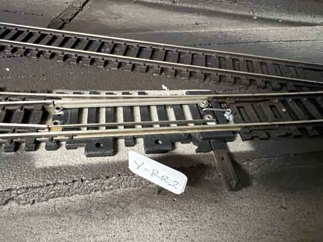
Instead of a mountain as before, there will be an upper area that is accessed through a switch and risers.
In the upper area, there will be a small town, train station, and a transfer station.
Both will have run-around tracks for the locomotives.
There will be another town in the lower level near the fiddle yard, with tracks used for deliveries to companies.
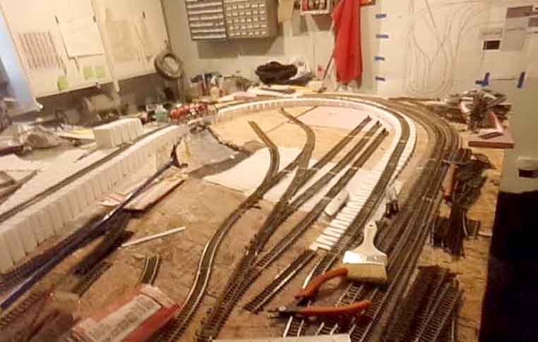
I have some pictures to share of the rebuild of Starrpoint. Please excuse the mess of the table as work continues.
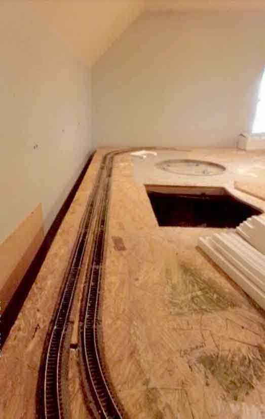
I began installing the double tracks in the rear of the layout. This was done so that the rest of the layout would fall into place with no issues.
The rear section will contain a tunnel underneath the upper section. Here is a picture of what the double tracks look like :
I will be using foam board for the sides of the tunnel and 1/8 plywood on top for the town, 7 switches and track. The reason for the foam board, less expensive, very strong and easily installed!
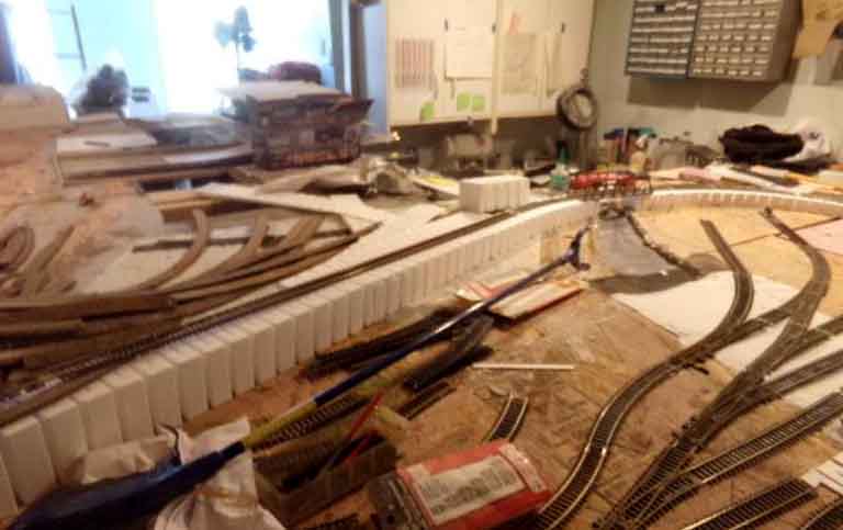
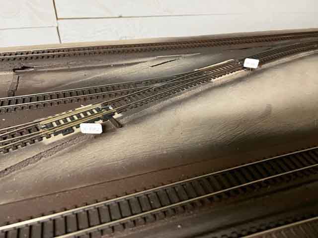
I have already installed the Woodland Scenics Riser package 2% grade to the upper level. The upper level is 3 inches above the lower level. Here is a picture of the risers with the track sitting on them.
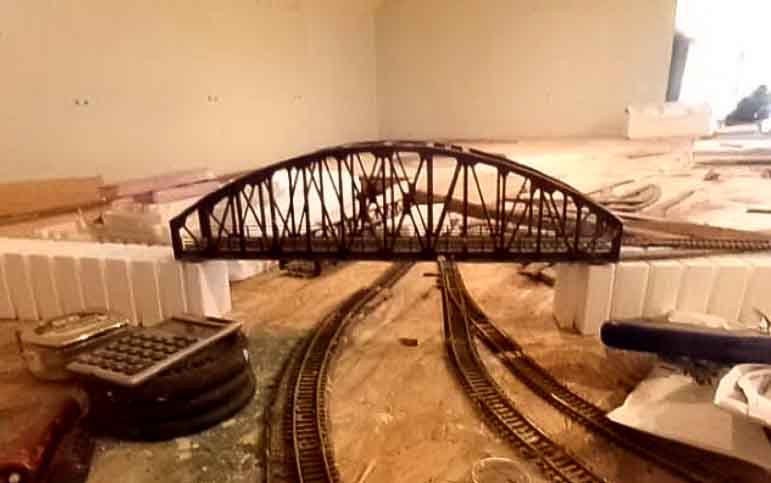
This picture shows the bridge that connects the lower level, over the risers, passess over the tracks for the main line and fiddle yard:
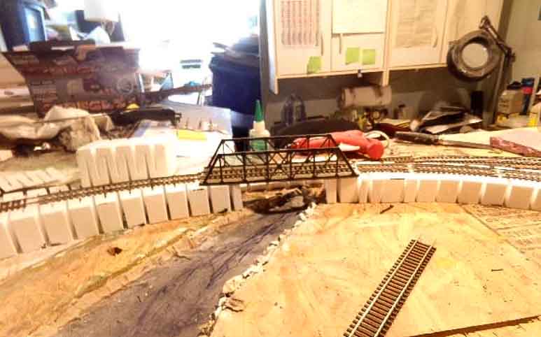
Here is another picture of the risers with a bridge over the water.
I will use plaster cloth to cover the risers and form the sides that will simulate earth holding the tracks above. I will place road bed on top of the plaster cloth and then the tracks.
Below is a picture of the fiddle yard and two tracks that will be used for deliveries to customers.
Next to this area that is open, will be a small village.
Well that is all for now. I will provided updates as work continues on the new Starrpoint RR
Jim”
A big thanks to Jim. You can see the layout he’s demolished here: HO scale mountains.
I love how he’s learnt from the first track plan, and just cracked on. So many of us would have been put off, but not Jim. Tenacity counts in this hobby.
Now on to Jon:
“Al
Here is an update to my layout.
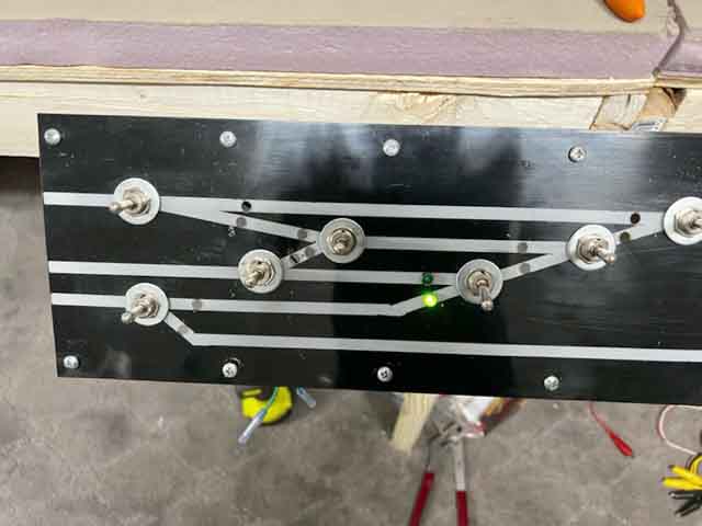
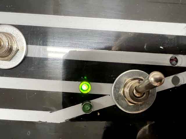
I’ve added a Control Panel for remote switching.
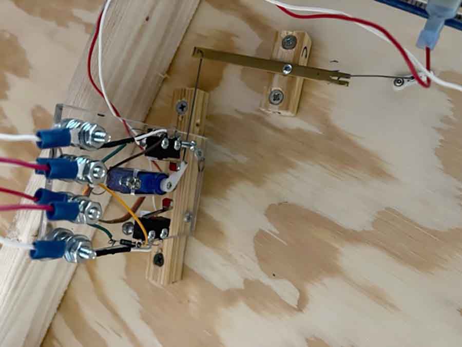
First I drill a hole for a guide tube.
Next install guide tube with retainer.
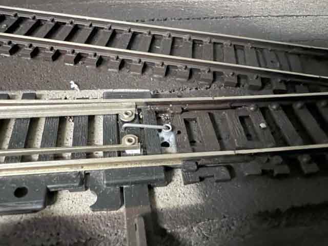
Then add wire. See close up at the switch. Each wire is custom bend for each switch.
Next is the lever then switch machine.
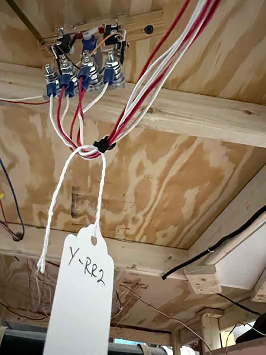
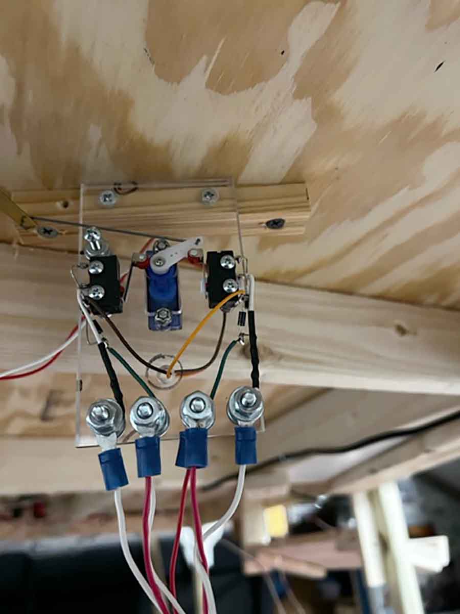
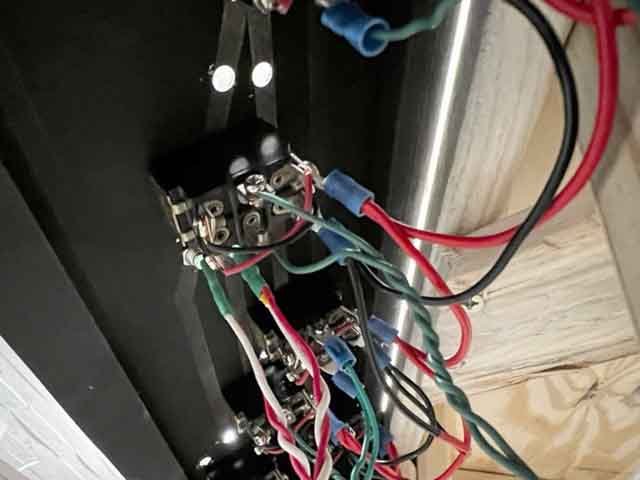
Note built the switch machines. Each one operates the switch and the control panel light.
If anyone is interested in doing this just let me know and I’ll make a “How-to” with parts and step pictures.
I don’t have the how-to as it is all in my head right.
How this inspires others to continue on trying different things.
Thank you,
Jon”
A big thanks to Jon and Jim.
Although Jim is starting again, he has had the heart to do so and I admire that. A lot of blood, sweat and tears go into a layout, not to mention time and finances.
Some people jump in feet first and it all works out fine. For others, a little planning goes a long way.
Of course I’m biased, but the the Beginner’s Guide is a sound investment.
So was Jim right to start again? I’d love to hear your thoughts on this one. Leave a comment below and let us know.
That’s all for today folks.
Please do keep ’em coming.
Best
Al
PS More HO scale train layouts here if that’s your thing.
Need buildings for your layout? Have a look at the Silly Discount bundle.

Jon, your layout control panel is so what I need and would like to do. At one time I could look at your excellent pictures and do it, but now at 77 I’m having a difficult time moving from seeing to executing, Any help would be really appreciated. Don
I fully understand the compulsion to dismantle and start again. I took apart my 12 year old N scale layout one year ago. It was a wonderful design with extensive double-track mainline, wide, sweeping curves (minimum 18” radius), realistic scenery, and operations featuring 14-coach passenger trains. It was my third layout, but I again wanted a new challenge and better/different design.
Have yet to make a start, but the main differences (reflecting lessons learned) will be:
– shelf layout instead of 4’ x 8’ (eliminate excessively long reach)
– one reversing loop instead of four (the single biggest frustration due to random, inconsistent circuit breaker tripping due to lighted passenger cars, sound locos etc occasionally drawing very slightly excessive current)
– hand-built turnouts instead of manufactured units (longer, more prototypical divergence ratios eg – minimum #10 configurations)
– hand-thrown turnouts wherever possible (minimal reliance on motorized switch machines/wiring/panel buttons … simplification!)
– fewer grades, no grade in excess of 1.5% (instead of 2% on the old layout)
– less hidden track, and more careful planning on location and extent of hidden track
– addition of 3 amp booster to my NCE Powercab dcc system (see note re: lighted passenger coaches and ESU sound-equipped locos above)
Hope to resume construction Fall 2022. In the meantime, perhaps one or two others can relate to and/or learn from my experiences!
Hi Jon,
Interested in how you made the switches.
Can you send a “how to” with pictures?
Thanks,
Mike in Voluntown, CT. USA
Hi Jon
I would be interested how you made your switch machines.
Thanks
Bill in Wisconsin, USA
Look great.!!!!!!
Not in my purview to say if Jim did the “right” thing in dismantling a completed layout to start a new one, BUT he did make adjustments/changes that he believed necessary based on experiences with initial layout. If we had his vision, conviction and, yes, tenacity, we might be well-advised to do the same!
Re Jon’s layout: I admire his wiring skills and sit in awe of how he works out electrical solutions, but that is so far beyond my level of accomplishment. It’s sobering to face such limitations. Guess I need to be Jon’s next-door neighbor!!
Just started HO layout, again. Had things stored for about 30 years. Somethings still had price tags from back then. Micado engine $19.95!!!
This time I’m trying to build everything I can from scratch. What are some ideas for Ballast, dirt, scenery materials? Any ideas will help.
Bud
Hello Fellow modelers,
Please email me to we can talk/email about layout issues and I can get you the switch machine how-to once I’ve made it.
Don,
I started by cutting a piece of plexiglass to the size I wanted my panel to be.
I then used Tamiya tape to layout my track plan (remember this will be backward so look at the tape from the right side to make sure it looks like the track on your layout.) on the back side.
Next I painted the back side flat black
After the flat black dried I pulled the tape up.
I then painted the back again with flat white.
After the flat white dried I painted again with flat black to make sure I had full coverage.
I made a wood frame with triangle mounting supports. Painted that flat black.
Before mounting the panel on the frame I drilled holes for the switches. Since the holes are a bit large it is easier to do the drilling with it flat on a piece of wood for support.
I then mounted it on the frame. Then mounted to front of layout. I used 3v LED lights and got the bezels from eBay.
I have a second power bus. It is supplied with 9v connected to a Low Voltage DC 1.8V 3V 5V 6V 12V 2A Motor Speed Controller PWM. (eBay item) This allows me to run the switch motors and LED at 3v. The switch motors will work on 9v BUT the “snap” move to fast and could break the plastic gears. Also, the Green LEDs are rated at 3.5v – 3.8v. Any more then that and they will burnout very fast. Yes I tested this. Poof done. Get a new light. One more thing. LEDs have to be wired with the LONG leg to + and SHORT leg to – else it won’t light up.
My switch machines have a 600ohm resistor inline to protect the LED. When I first set this up I used a larger power supply. I left the resistor in place since it would be possible for someone to the controller without me knowing it.
I will on the How-to to the switches later. Right now I’m going to work on install more switches.
Until next time. Happy modeling.
Jon
Looks fantastic! I am at the worst stage. Fit my tack plan ideas into my space!
Great Job!
Jon I am in the process of building a double deck and am just ready to start the trackwork and switching.
Love your panel and switches and etc. Can you please share the step by step and how to do. This is just what I have been trying to accomplish.
Great job!
I am at the start of something similar, but for a different reason.
My layout was in the (then) unused dining room, but “she who must be obeyed” decided she wanted some of that room to extend her kitchen. That left me with a much smaller space, I have uprooted the entire layout to the carport, which can’t be set up until the carport is converted into a garage (council problems). Just a minor setback, but hopefully I will have learned from mistakes made on first layout.
Jim violated the #1 rule of layout design: NEVER cover over any track with scenery until it has been extensively tested by running any and all locos and rolling stock over the track in both directions multiple times. Recheck all clearances on outside of curves and between trains on parallel tracks. Parallel tracks need extra space in the center of curves than between straight tracks. Make sure you provide easy access to tracks and trains inside of tunnels, either with lift out tops above or with ample openings from the back. Never depend on being able to reach a train thru the tunnel portal. Eventually you will likely add trees and other obstacles around the portal.
Been there, done that! I wrote on this blog site a few months ago, about having to face up to fixing a problem, and I suppose it’s one of the more recurring things we all have in common!
Al and et al,
Here is the reference I used to make my switch machines. https://modelrailwaylayoutsplans.com/make-your-own-railroad-switch-points/
I did some mods to it to make it work for me.
1. I used wood to mount the plexiglass to the table.
2. I use a lever as seen in my pictures above to connect the switch machine to the wire that operates the switch. This was the easiest for me to make adjustments as needed.
3. I added bolts studs to the bottom edge to make my connections the DPDT toggles switches and it gave the the ability to add panel lights right off the switch machines.
numbering the bolts at the bottom edge 1-4.
1 & 4 is for lights (connected to center pin on roller switch with 600 ohm resistor inline. This reduces volts to 3v so the light does burn out.)
2 & 3 power to motor as in the diagram.
Connect power to 2 & 3
Connect a light to 1v2 & 3v4. + lead on LED will go to 2 or 3 depending on which light set you are using.
Al if anyone has questions please pass on my email address to them.
Jon Aplin Rocky Top, TN
Hello Al & I’m Jon, yes I would like a break down of your switch wire, parts ect. Thank you very much Jon. I have been waiting for years to put my set up, up. So I have been buying this and that so I would have a really good base to start my layout. I have 0g & HOg , with the 0g up front and HOg in the back ground I am hoping to give some depth a long with my train lay out. Thank you again, Stephen Gispanski
A great rethink Jim.
Two things this shows for hidden parts of layouts.
First make sure all your locos and rolling stock will run smoothly in both directions on the track before covering it with scenery.
Second make sure the scenery can be easily removed to gain access in case anything goes wrong (because it will).
Cheers
Ralph
gives me some ideas for mine thanks.
Jon – I would love a “How To” on your switch lights! I have 5 switch tracks to do. Step by step with pics?
Steve
please do create a how-to guideline for wiring these turnouts. Returning to HO railroading after many decades away…Good info in your post!
Dwight in Toronto “– hand-built turnouts instead of manufactured units (longer, more prototypical divergence ratios eg – minimum #10 configurations)
– hand-thrown turnouts wherever possible (minimal reliance on motorized switch machines/wiring/panel buttons … simplification!)”
You read my mind! I’ve got a small workshop that allows me to make most any shape part I want. Way more fun than just buying something. Allows custom parts to be made “to scale”. A small metal lathe & milling machine + assorted accessories form metal or plastic parts and can also make molds to make metal or plastic resin parts, even rolling stock.
Very helpful thread, indeed.
I feel your pain, Jim. My first layout, Farland One, had many problems. I fixed many of them when I thoroughly identified them at the time, but some were so embedded in the layout that I had to tear Farland One down and build a new one to fix them. Looking back, I think my mistake was adding scenery before I had completely run and investigated what I already had. Once the scenery starts going on, people seem willing to fiddle with the track problems instead of fixing them because it requires ripping up so much completed scenery. Running the track for an extended period before adding ANY scenery is my lesson. What you are doing now looks very good.
Jon, nice work on the servos and track control.
Rob McCrain
Yes Jon, I’d be interested in a step by step and material list on how you did your project.
I am also interested in how you made the switch machines.
GREAT bridge; kit or scratch?
Hi Jon. I really like the way you have this setup. Any chance we / I can see how you mounted the switches under the turnouts? And also, I would love a copy in the step by step and material list on how you did your project.
Impressive work (re-work) on the layout. Because I got a GREAT deal on Tortoise machines, I went that direction. Simple to install and wire.
My 12 x 8 HO layout has 21 of them, conveniently controlled from my main panel.
Hi Jon,
I am very interested in your switch machines.
Wonderful tips for switching and it took a fair amount of experimentation to make it work.
Now a complete revamp and restructure of the of the layout to make it better with more detail and rail lines. We will have to wait on what comes out next.