John’s been in touch with how to make your own railroad switch points:
“Al,
I have been working on designing a switch machine that can be mounted under the table, and has power, flexibility and can be used to light signal LED’s to both show on the layout control panel, and on the layout itself.
There are good switch machines out there for sure, like the Tortoise® but I wanted my own.
All of the components of the switch machines were ordered from eBay from various vendors, and the plastic sheet from a local home store. One “storm door” ¼” thick (6mm or so) plastic should make several dozen machine frames.
The diodes are – 1N4001 Rectifier Diode 50V 1A
Micro Switches are – Mini Micro Limit Switch Long Roller Lever Arm SPDT Snap Action
The Motors are – 9G SG90 Mini Micro Servo For RC Robot – Helicopter
The Double Throw panel switches are – 6 Pin 2 Position ON-ON DPDT Mini Latching Toggle Switch
The description in BOLD is what you would enter in the eBay search for the components. Now for the details.
The best price for the motors is, about $0.65 each if you order 20 or so. The rest of the components come up to about $1.20 so the machine costs < $2.50 when completed. I found the cheapest prices for all of the stuff above from China eBay vendors.
The schematic for the railroad switch machines is:
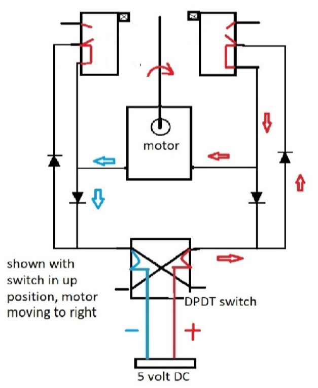
Please note the current arrows for the diodes are drawn by U.S.A. theory, Europe uses “common” theory which has electron flow in the opposite direction – pay no mind, the schematic works either way so don’t reverse the diodes.
If, when you build the machine, it does not throw, reverse the motor leads.
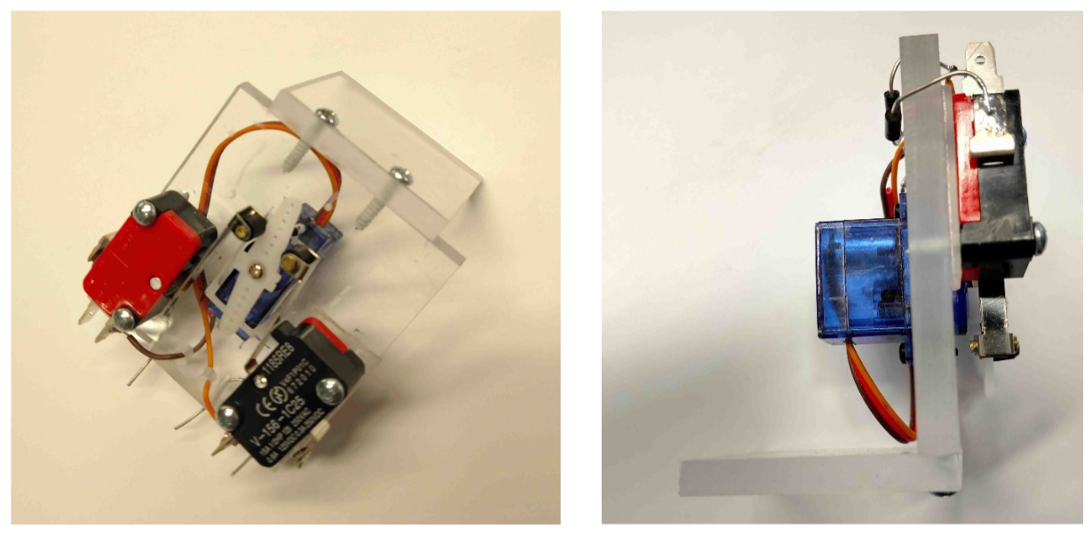
Note that when the motor goes to the right as the little arrows are indicating, the arm on the shaft will open the micro-switch on the right and stop it there. A “piano” wire on the arm goes through the board and operates the track switch.
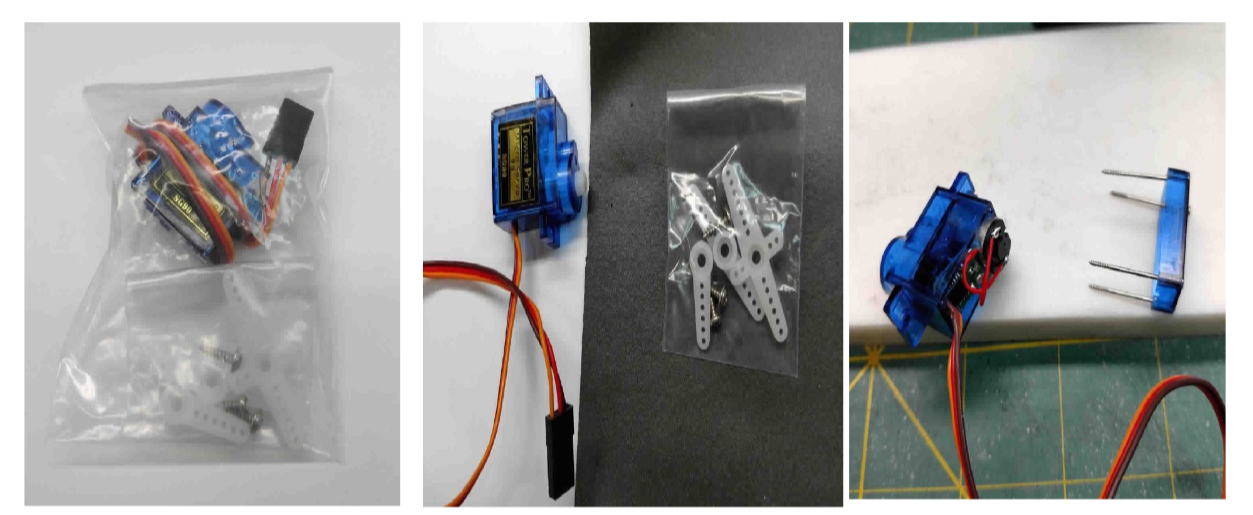
The motors as delivered need to be modified, as they come with a tiny circuit board that operates them by servo pulses. I wanted straight DC operation, so the PC board had to go.
The pictures below show how the motors come, and how they are modified.
Note: these will operate 180° but can be made to operate full rotation if the little potentiometer inside is removed too, but that requires taking the gearbox apart.
Use for the track switch machine is not required since the throw is only about 20° from center.
Also note these little motors are really powerful, with the gearing they can easily operate most anything on a HO layout, like bridges, turntables, or carnival rides. They are not full continuous duty, however so for accessories which would run more time reduce the voltage to about 3 volts.
(All images are clickable)
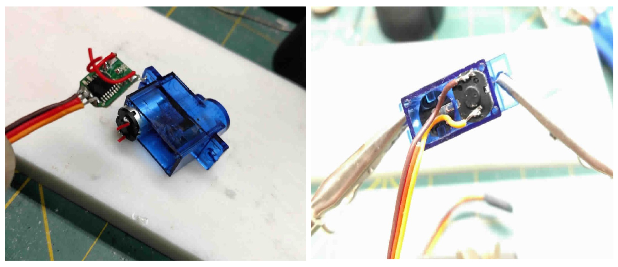
The pictures above show how the motors arrive, removal of the back cover and what’s inside – be careful here, the gearbox can come apart, but only if you mess with it.
Holding the motor body, remove the circuit board and re-solder the lead wires back to the motor – use minimum heat to connect the wires, and fine rosin core solder. Put the cover back and secure the 4 screws.
The next section is the preparation of the acrylic plastic sheet, I used ¼” Lucite® and have a little X-Y vise on a small drill press that I use. I lay out a strip with the motor openings for the sheet, then mill each out, cutting them off as they are milled.

When the plastic opening is milled, the corners need to be squared off, I clamp them in a vise and file out the remaining radius so the motors will fit.
.
I made a go gauge to assure the openings will fit the little motors. Because there is some play in the micro-switches, the tolerances can be pretty loose on the motor position, and where the actual switches are mounted.
The motors come with a number of actuators, like in the pictures of the accessory bags that come with the motor. I use the one with 7 holes because it’s the longest and hits the rollers of the micro-switches well.
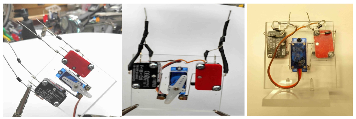
Once the diodes are soldered in, I drill a few holes for the motor wiring, on the early ones I put on heat shrink tubing like above center, but later found that I could route the wires on the diodes so a short circuit was not possible, like on the switches above right viewed from the back-the micro-switches are on the other side of the plastic, and those below. I’m not worried about bare wires, only 5 volts.
After about 6 machines done and the several small mods I made, I now have the entire process from cutting the plastic blanks to testing the machines down to about 30 minutes per machine.
As a side note, some of the track railroad switch on my layout, especially in the yards, are Atlas Snap Switches®, and these will be used with the stock switch solenoids.
I will be using DPDT center-off spring loaded switches instead of the slide switches the Atlas products come with. This is for no other reason than the consistent appearance of my control panel. For the 5 volt supply, I am using a rewired little train set power-pack with the speed potentiometer removed and a few other added parts to get solid 5 volts.
I know for many this will seem like a lot of work, but at $11.00 each and I need 29 machines, the savings are substantial, also I have constant 5 volts available at the switches which I can add a dropping resistor and use for the LED signals.
The final wiring for the railroad switch, LED signals and control panel will be another article.
John”
A huge thanks to John – anybody else made something similar to his railroad switch machine? I’d love to hear from you if you have.
That’s all for today folks, but don’t forget the Beginner’s Guide if you want all the shortcuts to make your dream model railroad, without the heartache, blisters and toil.
Best
Al
PS More HO scale train layouts here if that’s your thing.
Need buildings for your layout? Have a look at the Silly Discount bundle.

Thank you John. I had written off getting electronic switches because the amount I need would have set me back a fortune, but with you solution it has become a desirable proposition once more.
I look forward to your next article on the wiring and control panel with bated breath.
Gary O’Connor – Australia.
When I started reading this I wondered “Where do the pulses for the servo come from?” Your solution is very clever; it doesn’t need them! Thanks for the idea.
Very nice work. A couple of suggestions – you can drill little holes and mount the diodes with their through the holes, soldering on the other side from the diode bodies. This will keep them neat rather as though you had made a circuit board for them.
The other thing is that acrylic sheet tends to crack slowly, starting at the inside corners. It can take months but if that happens it will be a pain to have to redo them. At the least run superglue all round the inside corners to fill in the tiny stress cracks you can’t even see so as to at least delay this problem, or else use a less brittle plastic like grey PVC or polycarbonate.
Great “how to” article. Just goes to show what can be done with some knowledge and imagination. I look forward to the next installment.
Jack in PA
Hi John. Brilliant solution
Please could you clarify if you are using latching or non latching DPDT switches? Or does it really matter.?
Seems like a lot of work. Maybe if I only had to make one. This is one instance where I will spend money to preserve my sanity, and preserve time, since I’m seventy.
Wonderful idea ~ shall give this a go-about.
John what a brilliant solution. You’ve managed to get the price point for motoried points/turnouts to a place that just about anyone can afford. Thank you for that. Rob McCrain, Farland Howe
Great ideal! Thanks
Simple, practical, and genius. I’ve seen many of these same concepts work very well on large model railroads. And when you look at the bottom line being proposed, maybe some of the commercial market “switch machines” will get the hint. Well done John!
Thank you, thank you, thank you. I have a box full of burned out switches and a stomach full of frustration over switches. I am a Chemical Engineer (retired at 84) and am barely knowledgeable in electronics and I am doing back flips when I read your article. I am so appreciative of your contribution to our hobby I find it hard to express.
pretty kool build….
I’m not really an electronic ‘tech genius’ but it looks like a real $$$ saver
if one IS …
keep em runnin’ fellas
Great piece and I am quite looking forward to the second installment. This makes the concept both practcal and affordable for even the most electronics-challenged among us. I plan to jump on this as soon as the follow-up piece appears.
Thank you for the comments, I appreciate everyone’s thoughts and input. To the question about the DPDT switch, that stands for Double Pole (2 separate circuits) Double Throw (2 positions that connect wires). For my little machines, there is always 5 volts applied to the wires on the bottom of the machine, so these DPDT switches stay in position once moved. I plan to use this voltage for signals on the layout and on the control panel. The notes about the Atlas Switches indicate that they will have momentary DPDT center off switches which return by springs to center off position when released, no voltage out to any wires leaving them, because the solenoids on the Atlas switches only need a pulse, and if left on will burn out.
John
Thanks John, looks great, only one question, with tortoise type switches we remove the spring from the switch and the motor ‘holds’the switch over at stall. You mention your motors have a limited ‘run time’ do they still hold the switch/point over indefinately – as in under load – or do I need the springs to stay in the switches? Thanks in advance, Graeme.
To Graeme’s question – Do the switch motors stay over once thrown? Yes, because of the gear train, moving the motors by hand takes some effort, this is like “internal” friction so when they get to the end of their travel, they stop and stay.
john
Beyond me.., -Way beyond me! -Whew!! -Some of you clever blokes must be really electronically talented!!
I find it much easier (and more fun) just to use recycled 3-rail Marx turnouts; the manual ones for those closest to the table’s edge and the neat electric ones with their button controllers for further away, for across the board.
Realism you say?
It’s all in the mind of the beholder I say…
Nevertheless, ENJOY! ;>})
Thanks for the reply John, and for the info in the first place. I have a few Tortoise in, but cost, especially here in Australia has had me hold off buying more. Your help will get me back ” on track’. Thanks again, Graeme
The end switches are n/c correct. Really nice tutorial.
The micro-switches are DPST one contact normally open N/O, one normally closed N/C. When the motor activates the switch at the end of the travel, the micro-switch changes state and the N/C opens and stops the travel.
John
Thank you John for this great How-to. I have all the parts needed to make my own. About 17 of them. Love the fact that it didn’t cost a years wages to do this.
I’m about to start putting them together. I will be adding a light near the DPDT switch to show which track the points are lined up for. I wanted to use Red and Green for go/nogo but haven’t figured out the Red side yet. I do have the Green figured out. As the Leaf switch activates to stop the motor from turning it completes the circuit for the Green to come on. Also, I have to use a resistor to drop voltage for the LED.
Happy modeling.
Jon
Oh My !
I always say if I knew anything about electronics my railroad would be so much more fun. Thank god for the local hobby shop and the internet. I was a salesman and I know how to plug in my power source.
Thankfully all my trains are running just fine.
Hy John, good idea for reducing base cost of switch machines. I have one addition to add. I take and make a crank using 0.025″ copper wire from the switch at about 0.125″ arm then thru the table with about a 1.25″ crank arm under the table. Then I can connect two or more cranks with a straw and the switch machine moves the straw. In this way I essentially halve the switch machine cost. I also use dual red/grn Leds series the turtoise machine coupled via Fibre optic cable to the surface. Switch machine contacts are used for other control purposes. With this system only one wire at +/-12vdc is needed from control panel through the switch to common. I route wires using RJ45 connectors which gives me an 8 wire bundle. I also use sp12t rotary switches for yard switch selection. Anyway, I like your idea. Bob
I like your idea very much as I have been looking for a machine also . I have a question about the plastic frame are the dementions and the spacing of the micro switches important so the servo arm activates the switches? John Indiana
Hi European Electronics Engineer (MSc) here…
The electron current which has negative flow is explained during the courses but we use the “conventional” positive to negative flow of current when doing the maths and schematics.
Cathode = Negative
Anode = Positive and current flows from anode to cathode.
Best regards,
(Mr) Jan
Belgium
Sorry John but the average enthusiastic doesn’t know one capacitor from another . Not to mention the components you would have to buy would cost more then if you bought the switches pre-made. You’re talking too in-depth. What is a triode/diode ?
The Critic
John
I stumbled on a very simple yet effective switch machine that works for me but I had to get my head around something different.
First- servos have to be metal gears-not plastic -due to the torque curve of moving a gummy switch and that drives the price up. You dont have a lot of operating time but you do have forces that strain servos meant for very light torque. You really dont want to replace them once installed where they are.
My operator is a servo tester-$ 2.50 per- a gizmo with lights and a nob that turns. That dial not a toggle switch works the points. You mount the tester to your panel, wire to the servo, & that’s it. No work to the servo. The testers run from a 4.5 V multi voltage source from evil bay, one for the layout- $20. Works 9 switches.
The structure for the servo motor is as John described so I am about $6 to $7 max per point. I use piano wire that has a lot of give. I have one tester feed 2 servos where there is a crossover because you have to work the 2 points anyway and that kept the testers to a minimum so I have less testers than servos.
The tester may be modified to bypass the nob and wire in a DTSP switch but I wanted to test this out first and I was so thrilled with the superior switch function that I got to like the dial more and more. Servos are strong motors.
Working in lights and other stuff is where the micro switches become an add and needs more wiring but it eliminates diodes and keeps it simple.
Another thought
My experiment with the servos was to make a switch motor on the top so I did not have create a McGiver arrangement under the table and figure out tolerances and I could visually see how things worked. Most guys dont like to see stuff on top but this was an experiment. A few things came to light. One the servos are not large, two-the McGiver attachment was so simple, three -I could trouble shoot easy breezy. The experiment was beyond a success- and I have been playing with designing a box up on top that can go to either side of the turnout -lie the servo on its side to keep the height down and I dont have to go below! Right now I am trying to incorporate a signal light on top of the box and will keep you posted.
To Robert Brady (whose critiques always make me smile!) … John’s system is a substantially more affordable alternative to Tortoise slow-motion switch machines. He achieves the cost-savings by sourcing his components from China-based online retailers. And yes, the mechanical and electrical/electronic aspects require that one have some above average competency in those areas, so, not an easy diy for everyone. But the design does indeed provide not just the points-throwing function of a Tortoise, but also the LED position indicating features as well, and can save the hobbyist roughly $30 per turnout. That’s pretty significant.
Very good & clear instructions into the build. Might have a go.
Dwight I’m so glad I make you happy.
I like this approach… of coarse I would. This is a separate hobby in itself and can see why much experimentation was necessary. Certainly agree with low voltage and formidable insulation not required, maybe some spots. Also the drilled holes in acrylic for jig bent components, squaring things up is excellent suggestion. Used to use an insulating enamel to coat circuit boards/components completely even had spray can version.
Never had problem with plexiglass and stress cracks, don’t doubt it at all though. Made bunch of covers, insulators and most things forgotten. Reversed blade on table saw and cuts better than wood. Can also bend 90’s in the stuff quite easily with a bit of propane torch heat. Can even reclear, remove scuffs on the stuff with light flame run over areas, within reason now… on and on. Once upon a time was paid to know such things, paid to just stay at home now lol.
Regards, R
I have made a similar device with MG-90 servos. I 3d printed a holder, and utilized an ESP-32 for a controller, that is mounted on a custom PCB board to control 12 turnouts.
I run the servo and ESP-32 at 5 volts. There is a pair of limit switches to control the dcc power to the frog.
nteresting wiring tutoring, have to see if mine will need this.
John,
Wow what an ingenious cost saving idea. Thank you for sharing your knowledge and expertise. Waiting for the next installment to see how you connect to the track switch and wire in the leds.
Regards,
Donnie
Maybe a good idea but I think everything is getting a little out of hand, what happened to the old way of setting up a model railroad. Good luck if you ever run into a problem or burn down your house (LOL) !!!!!!!!!!!
Steve’s reply cracks me up lmao.
R
I don’t see where the black wire goes. I see the red and yellow connected but not the black wire. Please let us know.
I’m not a fan of acrylic plastic. For a little more $ you can buy polycarbonate or acetal that will not stress crack. They are super strong & long lived. If you use acrylic, use a smaller router bit or end mill to cut the perimeter and make the cut go past in each corner to eliminate needing to file a squared out corner/stress point. This can be easily done using the XY table on a drill press. Run the press are the fastest RPM it will go and keep moving. HSS end mills are widely available in a huge assortment of sizes. Use two flute for better chip flow. A mini lathe and milling machine can really add a new dimension to this hobby. You can make or repair many things with these tools. Mini lathes come up used often, as people move to larger machines.
I would be interested in purchasing one of your switch points to see if they meet my needs. I presently use atlas undercounter switch machines and electronic turnout switch controllers from a gentleman in canada for my work in progress n scale layout. This setup provides all the functionality you speak of but you may have a cheaper price point which if you have a lot of turnouts is important. If you are interested in selling me one, let me know.