Dean’s been in touch with a fabulously clear ‘how to’ on something that is always popping up on the blog: wiring a model railroad.
“Al, greetings from Dean in New Mexico. Thanks for all your good work supporting the hobby!
One of the bigest bugaboos of people starting out in model railroading is wiring.
So this is a short tutorial on wiring the track, testing it out, and soldering.
To start, I recently was asked “why do you use so many feeders in your model railroads. I’ll begin there.
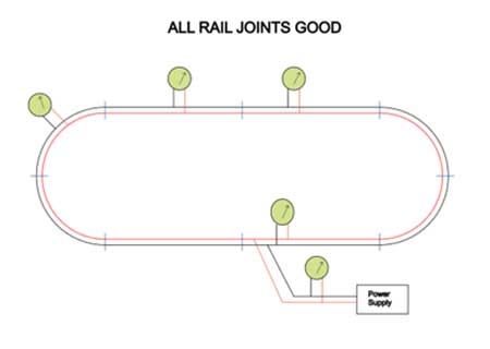
Here’s a simple loop layout. One of the two rails of the track is black, the other, red and the blue slash lines indicate rail joiners between the track sections. The circles with arrows represents a voltmeter measurement and they are green idicating correct voltage at any point you might measure.
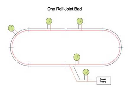
A bad or loose rail joiner will limit power to some parts of the layout, but with one bad joint you still get power everywhere.
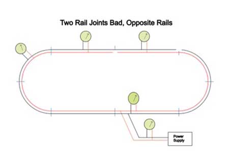
You can have up to two bad joints if they are on different sides of the track. You can see that in the diagram below–all sections of the track get power from one side or the other.
But, if you have two bad rail joiners on the same side of the track, you will get lower voltage (loco will slow down) or even no power (loco will stop) in the section in the middle (indicated with a red circle).
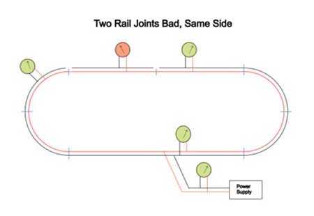
You have two options to repair the track: You can solder the bad rail joiners, or you can add a set of feeders, or jumper wires to the bad section.
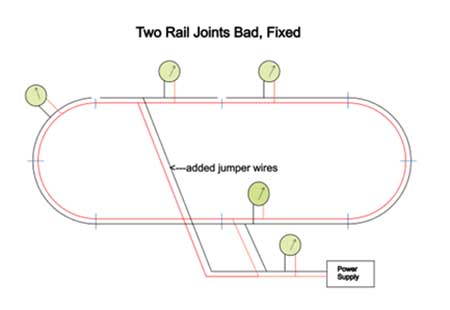
People have different philosophies on how many feeder wires to add. Some go as far as to add a feeder to each section of track.
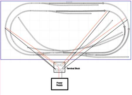
In my current Conejos Valley Railroad, I’ve put in four sets of feeders as you can see.
Then if a siding or other section of track goes bad in the future, I’ll add a feeder to that section.
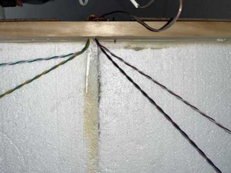
The photo below shows the four sets of feeders coming back to the same point. I chuck the two wires in a drill with the other end held in a vise, then run the drill slowly to twist the wires together.
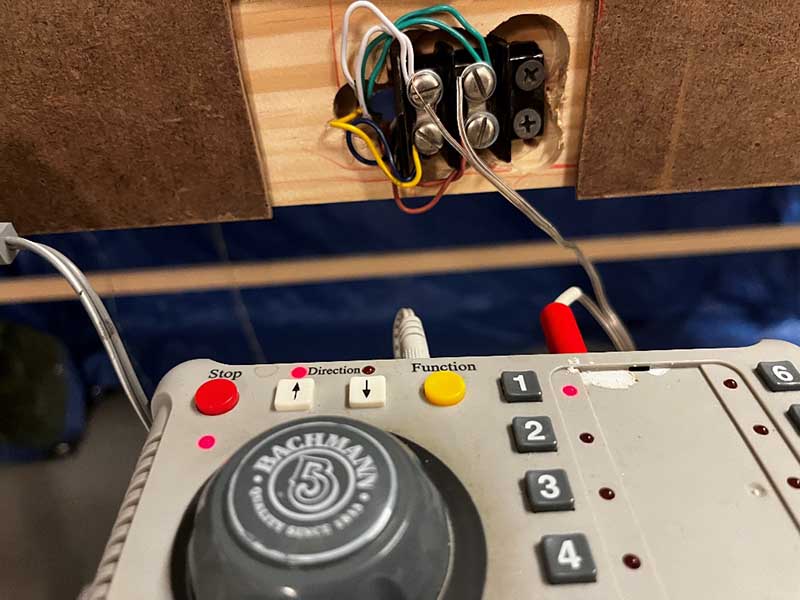
Here’s the terminal block where the sets of wires are connected to my power supply.
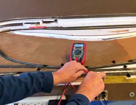
Testing the track. Here’s an inexpensive voltmeter that you can buy on Amazon for around $12.
If you are running DC power, set it as shown on 20 volts DC. I’m testing it out with a 9-volt battery, but you can measure your voltage easily at various points on your track to look for bad sections.
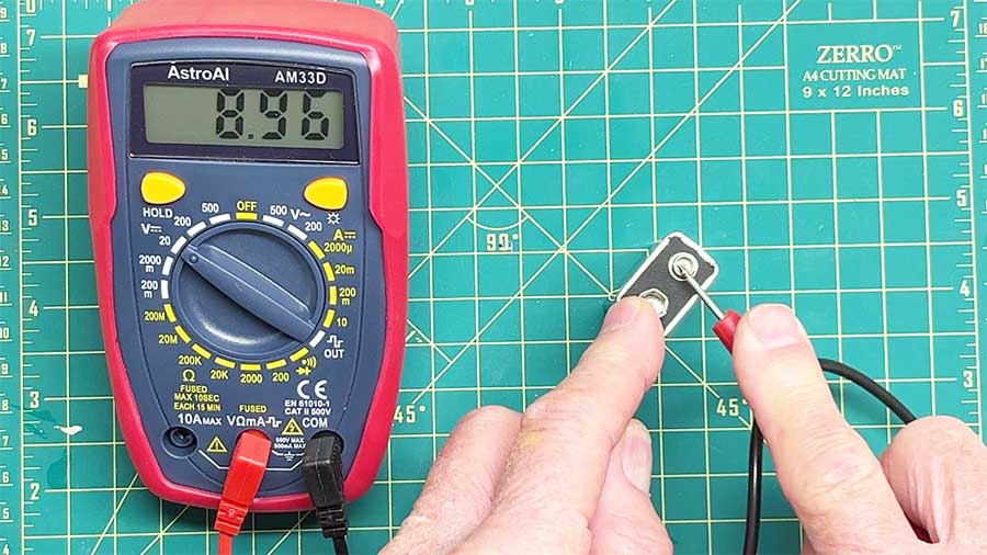
My railroad is DCC powered. DCC is actually alternating current, so for that set your volt meter to 200 V AC.
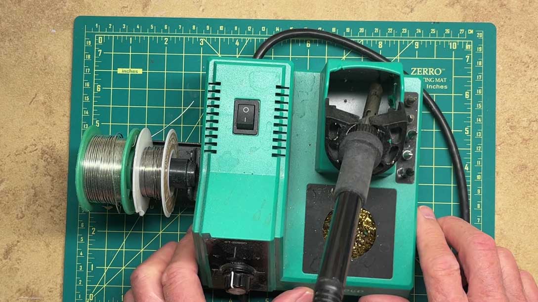
Soldering is easy if you have the right tools and solder.
You can get a soldering station such as the one below for $40 to $50 on Amazon.
You can vary the temperature of this one (I use 200-220 C) and it comes with rosin core solder that is safe to use for your track or wires.
The rosin in the core helps the solder to eat away corrosion on the metal. Don’t use acid core solder which will eventually corrode the metal.
To solder anything, first “tin” the solder point by touching the hot tip to the end of the solder wire.
This coats the point with a thin layer of liquid solder to help heat transfer. Then heat the metal and after it gets hot enough, feed the solder to the metal.
If you’re careful, you can add jumper wires to existing track after it is put down.
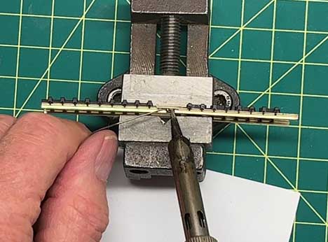
But the best way to add jumper wires to a layout is while it’s under construction – as you lay the track you can add hidden wires to the rail joiners.
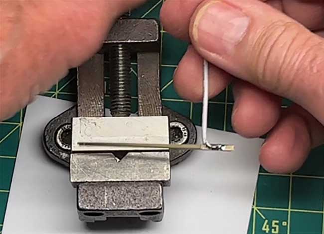
The wires can be soldered onto the rail joiners at your workbench by holding them in a short piece of track. Solder a blob of solder to the joint, tin the wire and then solder it to the joiner.
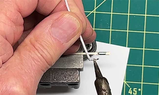
Test the finished assembly to make sure its sound, then slip it onto the rail end as you lay down your track and pass the wires though holes in the track support.
I’ve put out a YouTube video that shows all of this in more detail:
Hope this helps.
Cheers,
Dean”
A huge big thanks to Dean for sharing his ‘how to’ on wiring a model railroad.
I have to say, I think it’s a wonderfully clear post on wiring.
You can see more from Dean on wiring here: How to run a model train bus wire.
Please do leave a comment below, I’d love to hear your thoughts on this one.
That’s all for today folks.
Please do keep ’em coming.
And if today is the day you get started on your layout, the Beginner’s Guide is here.
Best
Al
PS Latest ebay cheat sheet is here.
Need buildings for your layout? Have a look at the Silly Discount bundle.

The whole point of dropper wires is to ensure a reliable supply to all parts of the layout because rail joiners cannot be relied. ….it is a waste of time soldering droppers to the joiners . Best practice is to solder to the rails.
Beware not all “voltmeters” are the same. I bought a multimeter that seemed to test conductivity from the description, and from a reasonable manufacturer. Alas, that was one thing it didn’t do …
Thanks very much Dean,great tips for powering the track,will use them for my railway track.
Great information , thank you for sharing your insight . I’m a beginner and rather inexperienced in electrical stuff so you have enlightened me significantly with your tutorial. Patience and practice seem to be key in this hobby , combining those with the magnificent info and input from someone like Dean is very encouraging … I feel like I’m learning, thank you .
Meters… always liked the Simpson 260 which was analog display. Fluke has been my standard now for decades, digital. Polarity makes no difference, if wrong will tell you so with correct readout regardless.
As far as rails or joiners to soldier, jury’s still debating which might be best I’d say:
1) Is flex rail in use or all plug and play short pieces?
2) Nobody mentions heat expansion and contraction of rails. Joiners serve as expansion slides to be considered as prototype does.
3) The 4 conductor telephone cable works perfect for rail soldiering either side of joiners. Small solid strand 4 conductor stuff, color coded even. This can carry 120 volts AC, no problem. Yes, know about the hard way getting zapped (by accident, alarm systems and such generated on pole lines). Before “cell” of coarse.
Find no fault with joiner jumping, good topic and good idea. May even be the better fix, can’t really say.
Regards, Rich
I use flex track and solder the joiners. Still solder on feeder wires every six to eight feet, as well as after every switch. DCC layout, so I don’t have to worry about separating blocks. Wide curves, glueing to cork roadbed and a fairly constant temperature environment should account for any expansion issues, I think.
I’m a newbie. Thanks, the subject was just in time
Thanks for the focus on wiring, especially good for those starting out in this hobby. Trains don’t run without electricity. It can be frustrating but worth the effort and time.
Dean’s wiring advice is good advice. Owning a volt/ohm meter or multimeter and knowing how to use it is something all model railroaders should have and know how to use. I use mine all the time when setting up or diagnosing electrical troubles on Farland and the N scale efforts. If you don’t know how to use one, you can google it, youtube it or read the instructions that come with it. The most useful function is the continuity testing capability. Rob McCrain
Solder to the rails, not the jointers. You are still relying on a mechanical connection for conduction.
Good Basics of Model RR Electrical Wiring… ALSO,,, I have a friend in our Model RR Club here who has an O27 Scale Layout. He brought in a New Locomotive to test on the layout… It Had it’s Own Rechargeable Lithium Battery Power Pack inside the Diesel Locomotive Shell Body. My Guess it was a Williams Brand. It ran on his layout using that internal power pack and a Control App that was downloaded on his Cell Phone! SO, you can RUN locomotives on your Layout that are battery powered! From Mike In N.H. U.S.A.
I have a dcc layout. I have my joiners soldered more for alignment than conductivity. I solder feeders to the rails. Dcc needs a good signal otherwise the decoder won’t respond properly. The further you get from the command station you need feeders there to prevent voltage drop and the rails need to be clean.
To avoid voltage drop and dead track, I ran feeder wires under the table underneath the track. Then every other 3′ length of flextrack I used powered track connectors and ran them under the table at the junction and tied them into the “bus” running under the table! Works fantastic!
Dean…. If not the best then one of the best electrical instructional blog and video I have seen.
Fantastic job. I have stored this in my library if “HOW TOs”.
Great job on the wiring thanks
I absolutely enjoy your varied presentations. The people with whom you correspond regularly are often extremely good a and practical in their discussion of model railroading issues and problems.
I moved to a new location but am pretty old so I;m still thinking about whether I should get back “in the saddle” as it where. My interest won’t change – no matter what my decision is.
To add to Dean’s comments on the wiring I soldered 0.75mm droppers to every length of track I installed, mainly because my 00 gauge layout is in my garden, these were then soldered to a 6.00mm track bus, I have approximately a 200ft. running loop of track which is mounted on 4ft. high posts to save my knees. I know it sounds a bit over the top on wire size but I don’t get any voltage drop anywhere on the layout or any dead spots, rail joiners are only used to keep the track connections in line.
Many thanks Al for all your great work in keeping one of the very few items of sanity saving on the internet running as you do.
Very helpful post thanks – here is a variation I have found effective for my American Flyer S Gauge 18 x 30 layout (I mention the dimensions because full room layouts like this must have feeders to operate properly)
Instead of twisted feeders staring out from a power supply I have run 12 gauge solid copper wire thru my bench work – I operate my American flyer trains on AC so there are 3 simple wires: Black (Base post) White Variable AC (0-18V with respect to the Black Base post wire) and Yellow which is constant AC Voltage again with respect to the Black Base post wire. Now I can tap into this bus system anywhere I need to add a feeder to maintain a good quality connection to the track. I’m leaving details out like how I handle blocks and multiply independent main line tracks but you probably get the gist from my basic description –
good tips on wiring. thanks.
Any help and advice for O gadgets 3 rail track users like myself?
Hi Dean,
As I’m building a DCC layout, I’m wondering what gauge wire you’re using for your feeders. Thanks. Jerry
Thank you Dean,
Andrew in Oz
Hi Al, I recently discovered these pliers that hold 2 wires together while you solder them. Great for when you’re under the layout. Works like a third hand. https://amzn.to/3Ci8GOf