Tom’s been in touch with is O27 model trains:
“AL
It has been A while since I submitted something but I finally have enough completed and of a good quality that I can show it. I work with O27. It was what I had the most of and it goes back years for me. This post will be about my new control panel. Me layout is DC. Someday I would like to try DCC but all my locomotives are old and DC.
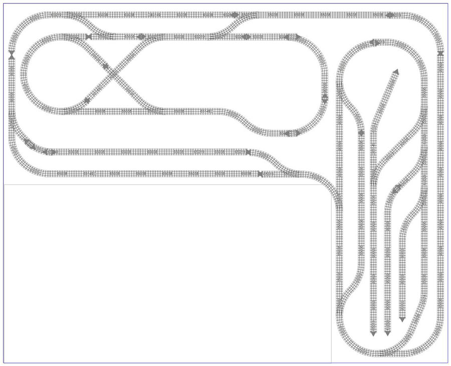
Pict 1—this is my track layout so you have an idea of what I am working on.
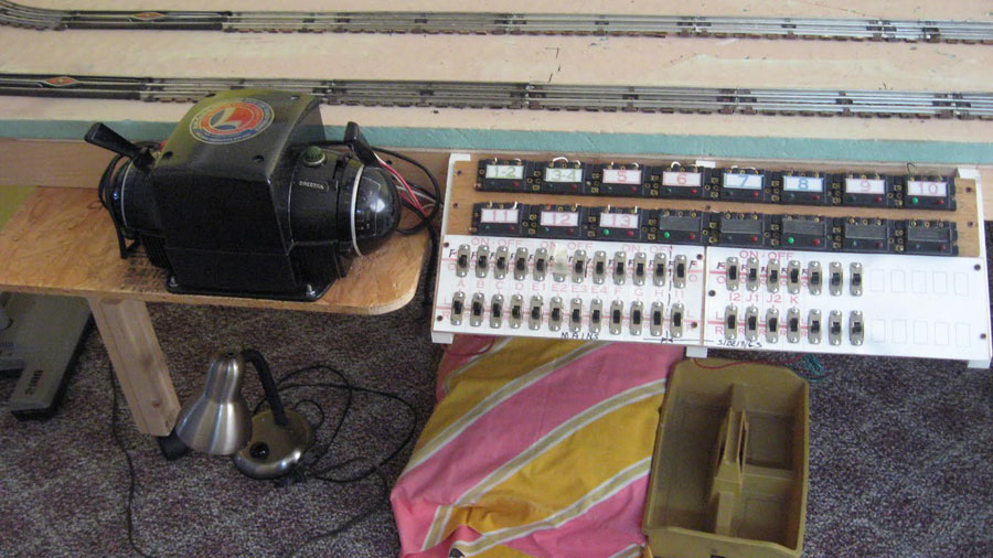
Pict 2—this was my temp control panel to test track and switches. I made It from old switches and wire I had on hand
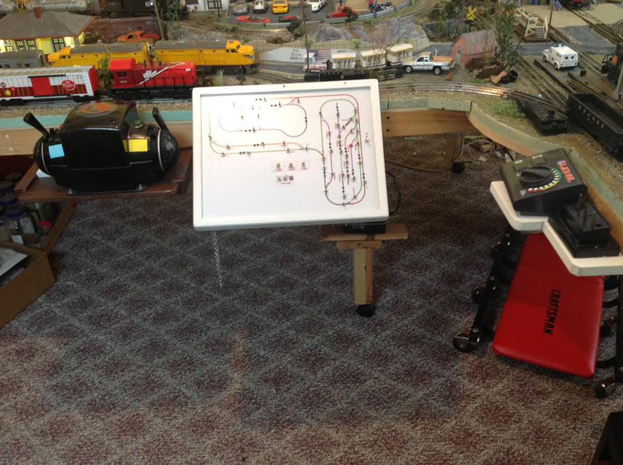
Pict 3—this is the new panel and transformer. You can’t see it in this picture but just to the right is a small transformer that can be used to run a train in the yard to build a train.
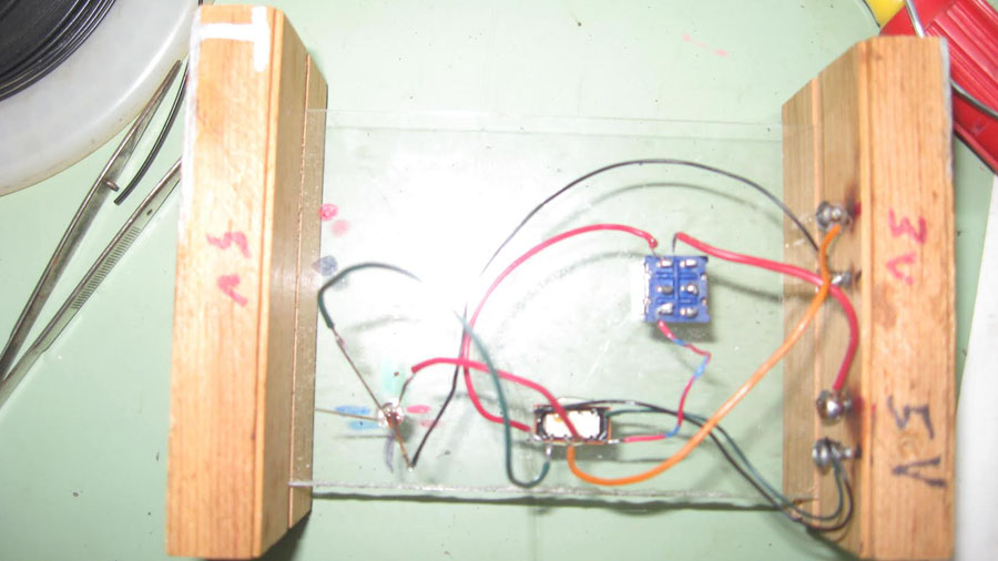
Pict 4—this was a test wiring for switches with LEDs. All my switches are old Lionel O27 #1122 I picked them up for good prices at train shows and rebuild them.
I took them all apart and rebuilt them to work on a separate power supply. I don’t need the track power on to work the switches. This works nice because it gives me time to set the switches up in the direction I want to go. It was a lot of work but worth it.
One of my biggest problems was how to operate the switch and have the red or green LED stay on. The switch is a momentary single but the LED is a fixed low voltage.
There were a few ways to do this but I was thinking about the price. I have 18 switches so it adds up fast.
I used a DPDT momentary switch with one side working the switch and the other half tied to a double coil DPDT latching relay that controlled the LEDs. I played with this for months but it works perfectly.
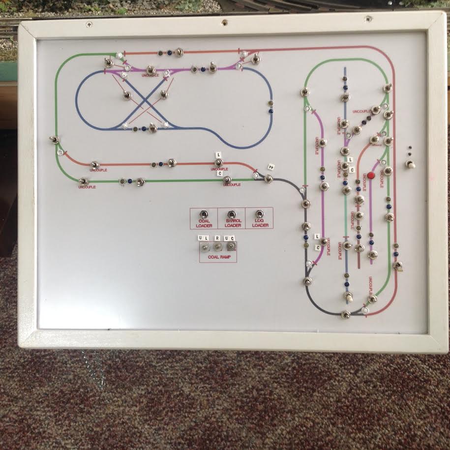
Pict 5—this is the new panel it is a sandwich of a piece of plastic, a picture of my track layout done on Auto Cad and a piece of hard board.
Each track section has a DPDT center off switch that changes the transformer side and has a duel color LED, blue or yellow to show which lever works that section.
All the uncouple tracks have been rewired so they work with a SPDT momentary switch I think there are 16 of them.
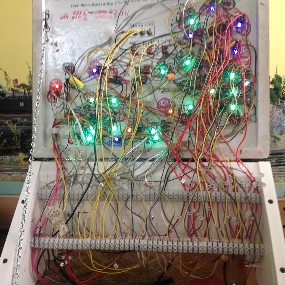
Pict 6—this is the panel wiring as you can see there is a lot going on. I have had a few small problems with a solder joint coming lose and a LED go bad and let me tell you it was not fun to fix. No really I enjoyed it.
O27 model trains:
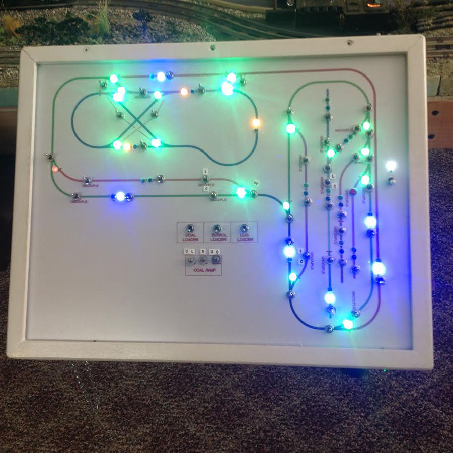
Pict 7— this is the new panel with lights on you can see the LEDs are a little Bright I am happy with the panel it does everything I wanted it to do.
Now that I have it complete there are a few things I would do different on the next one. I would have made it just a little bigger. Some of the switches are very close together and it was hard to wire.
I should have given a little more thought to the wire layout it got very congested back there. I should have used more different color wires and the LEDs are a little bright.
That’s it for now. I am working on pictures of the whole layout and may have more next week
Steve from Toms River ”
Next, on to Paul:
“Hi Al,
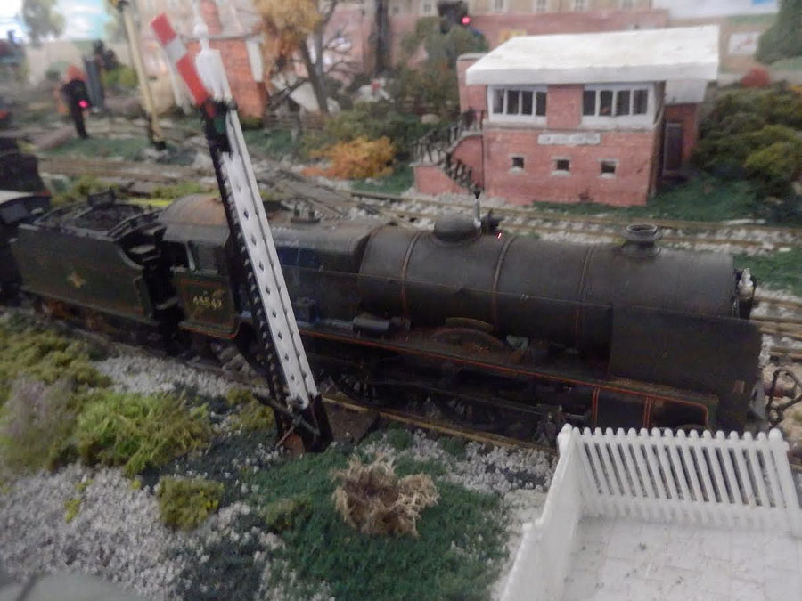
Here is a photo of 45543 in 1960s condition after I weathered it.
I used a thin wash of grey, black, and brown water based paint mixed together, to create the grime and dirt and soot.
I also painted on the stripes, which warn that the locomotive is not run under overhead electrification.
I used insulation tape to guide my paint brush, when I did the stripes.
Paul”
Now on to John:
And lastly John has been in touch again – yesterday I said I had only every published two shunting puzzles. John replied with” “At the close of this installment I noticed you said that you have only published two shunting puzzles…
I know you have published 3 or four of my little layouts.. Shunting puzzles each…
You mentioned you were going to publish my “Lostend Foundry” layout )another puzzle featuring your cutout scenery but I do not recall seeing it published… Would you like me to resubmit Lostend Foundry?
Sincerely,
John from California”
Apologies to John – and yes, please resend your Lostend Foundry (I get so many mails it’s hard to keep up sometimes).
In the meantime, here’s one of John’s previous posts.
A big thanks to Tom for sharing his O27 model trains.
That’s all for today folks.
Please do keep ’em coming.
And if today is the day you get started on your layout, the Beginner’s Guide is here.
Best
Al
PS Latest ebay cheat sheet is here.
PPS More HO scale train layouts here if that’s your thing.


To Steve: Boy you did a great job, congrats. I have the same problem with my turnouts I use kato track and turnouts, The switches are also kato, they are as you say momentary contact I wanted to have leds to show where they were set. Could you post a wire diagram of how you did yours. Boy I thought I had a lot of wiring, you blew me away with that picture of yours. Any advise will be appreciated. THX Tom in Payson AZ
Steve,
Nice work. Steve. I agree that your LEDs are too bright. May I suggest that you put a small resistor in line with each one? Start with 100 ohm and experiment until you get the effect you want.
Pete from California
I am almost going to do exactly the same. Thank you for your advice. Once completed I will send to Al
Hi,
Could you please tell me the size of this layout? I’m in the process of creating an ‘L’ shape also with two 4 x 8 sheets of plywood. I have O27 track and surely cannot fit this much track on the platform.
Thanks.
Tom
Bravo Steve: Very interesting arrangement of switching directions of trains, along with sufficient sidings for actions of accessories. My brother and I used to run the Bricktown Train Shows at the Elks Lodge, along with the Bayshore Train Show at Holy Family School in Union Beach, both in NJ. Did you ever attend? Enjoyed your pictures, show more. Lou Di
Impressive!
A note about O27 gauge Lionel trains. I see you have a Lionel ZW transformer and 3 rail Lionel track. That transformer puts out AC to the track (the label on top says 60 cycles). The trains, therefore are not DC, they are AC. Converting to DCC may not be feasible.
I’m in the process of rebuilding my layout. I plan to build a control panel similar to what you have done. You did a great job with yours, especially making the wiring accessible without crawling under the panel. The layout is great too.
Kinda reminds me of the old “Lite Brite” toys. No offense, you have done an excellent job. Keep up the good work. Still trying to find some body who can show me how to put my layout pictures into my computer and then send them to Al. I’m sure most would enjoy them.
Is there someway to enlarge these models to O scale?
Very cool, I like it.
Steve’s system is excellent and worthy of praise! Almost anyone can lay tracks, but Steve shows us that the exciting part is finishing a working switch system that you can share with others. Great Job Steve!!!
Looking for an old book with the title “Model Train Electronics.” In it there was a design for a “Diode Switching Matrix.” I built one in 1984 for an antenna switching system using over 50 antennas. I could create a complete path for the antennas just by hitting one momentary switch. Later, I used the same design for what it was intended – my HO train layout. One click and all the switches needed to move a train to a specific track was done. Each switch acted as if I had a separate circuit for it. I wish I could find that book again. It was published by some company in PA, with the word “Hill” in the address. I spend more time on the electronics than I do on running the rolling stock. Y’all that have complete set-ups are truly the lucky ones. I’ve never had a set-up that was complete.
What do you use for the scenery?
Thanks
What do you use for scenery around the towns and tracks?
Thanks
John
I would like to see more of the 027 layouts
I have a question on LEDs. Steve’s LEDs are too bright and Pete suggested adding a resister in line with each one. Would it work to add just one resister in line with the common leg of ALL the LEDs (if they are wired that way)? Or add a resister in line with the power supply? Admittedly, with so many LEDs, it would need to be a resister with a higher wattage rating. I upgraded an engine to DCC and used one resister in line with the common leg of the headlight and backup light, and it works perfectly.
Carl in Kansas
So, Paul’s first picture is definitely not 027, but the weathering was very realistic. I would be interested in more detail. I never did find the stripes he talked about.
Comment to Carl: That would only work if the same number of LEDs were on at any one time (as in your loco – only one at a time). Otherwise the brightness would change depending on the number of LEDs drawing current.
One option that works in some situations (say when two signals will always be ON together) is to wire them in series with one resistor.
good looking layout
Steve Great job! What are the dimensions of the layout? Looks pretty impressive. I used to live in TR many years ago. Sibs still live there. My daughter has a bakery downtown. I hope someday to have a layout as nice as the ones showcased by Al. Keep up the great work. Cheers! NJ Mark
Not sure if DCC is the same as Lionel legacy system or not, but I have legacy system and run it off of a ZW transformer. so not sure if there would be a problem with the AC current or not.
unbelievable job. the wiring would sort me out nice job. would like to see more.
Love the O-27 layout. We dont see to many of these. The control box looks like a wiring nightmare. How did you keep it all straight? Would love to see more photos of layout and trains
Pete-Rainy Silicon Valley.
Pete
Yes the wireing was a small nightmare but the challenge made it fun. I did the wiring in layers.first I installed all the switches and LEDs. I labeled them with different color markers. Then I wired by systems. First the switchs than the track power and finally the operating equipment. It got tough by the end. I have gone back to fix problems and change bad LEDs and it wasn’t to bad. I also dimmed the LEDs with some well placed resisters.
I will be sending in pictures of the layout soon. I have to get a better camera.
Steve from Toms River
looks good
Hi Al
Are you still there, is it possible to be re connected with your e-mail, if you are
God Bless
Steve