“Light bars for lighting cabooses or passenger cars can be made from 5mm LEDs and clear drinking straws. One in each end wired appropriately. The light carrying medium is 5 minute epoxy from one of those Loctite instant mix tubes. (One minute epoxy is too fast and sets in the mixing tube.) Squirt it into the straw, cap with the LED then cap the other end with the other LED. This is all much less expensive than lighting kits. With the new Evan Designs LEDs, no decoder is needed. Any voltage source works.
Michael”
“The best tip I got when starting an HO layout,was to spend the extra cost for nickel silver track.
Richard”
“Dear Alastair
Sixty years on I got my train set out again, invested in new track etc. and off I went only to find I am not that clever.
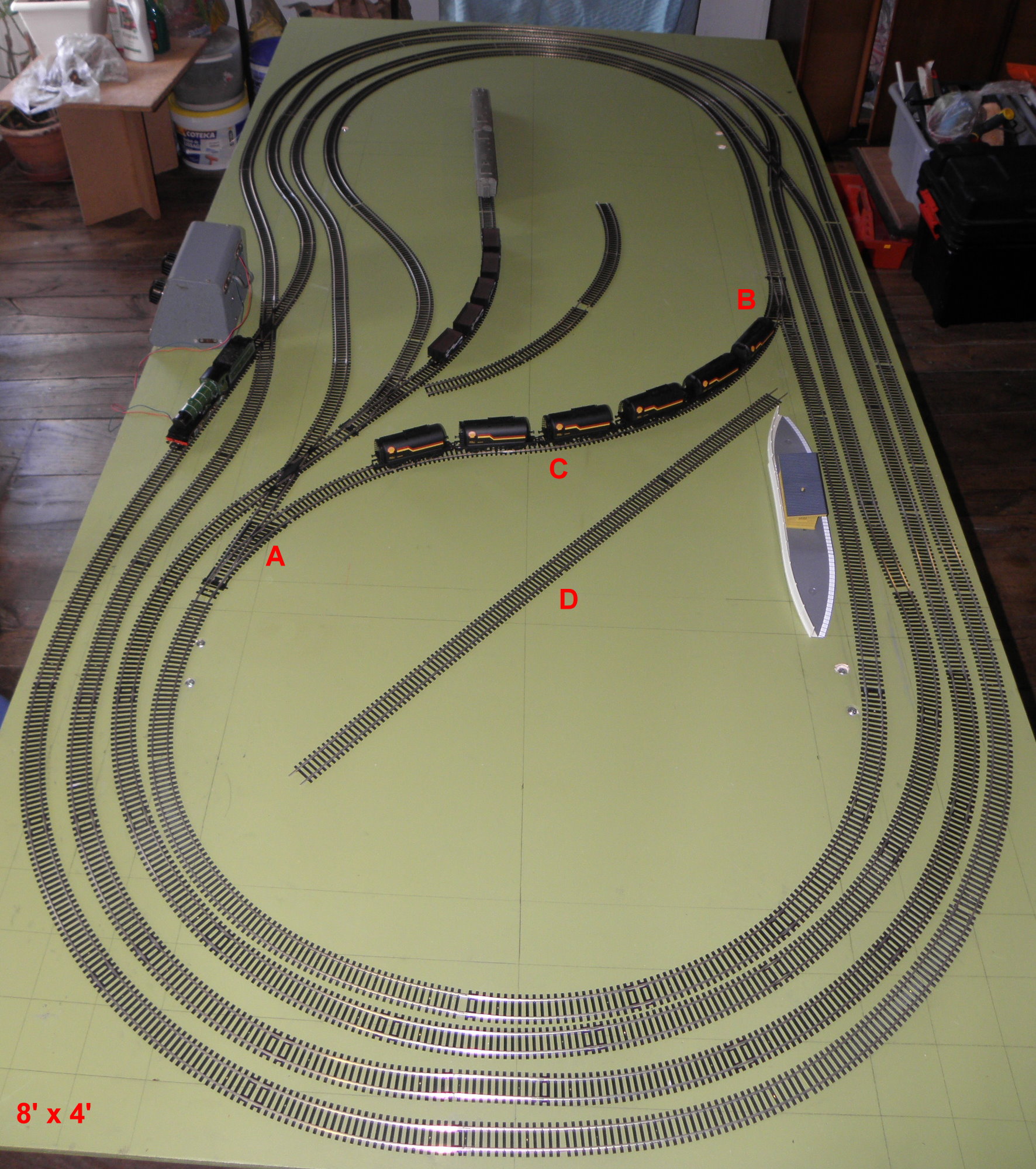
I was trying to set up a continuous loop using four tracks but hit problems when I tried to put in a cross over to reverse direction.
See attached photo: I want to cross from “A” to “B” and inserted insulating fishplates at “C” but when the engine gets to the fishplates it stops ! !
Could I solve the problem by inserting “D”, adding insulating fishplates at each end and wiring in a parallel electric supply to that section ?
The points at either end are Hornby R8073 & R8072.
I have looked on the Internet but am getting more confused. Can you advise please.
Please excuse track spacing, I am only running single track and tried to gain as much space as possible.
Thanks in anticipation
Bernard”
So who can help Bernard?
Latest ebay cheat sheet is here.
Best
Al

You need to reverse the track polarity on the diagonal track, most suppliers of Dc. and DCC equipment can supply this device. Regards
What you have here Barnard is a reverse loop at “A”. You need a completely isolated section north of “A” to reverse the polarity of the track. And a double pole double throw switch. I would recommend a book on track wiring.
I think Bernard has a reverse polarity conflict and therefore the system is shorting out.
There are auto polarity reversing kits but as far as I know, they only work with DCC layouts.
Those with lots more DC experience I’m sure will advise but believe separate power feeds will help but the loco will have to stop as the polarity is manually switched as it enters and exits the reverse loop.
Hope that helps a little towards a solution.
Dave G
Surely you need a reverse loop controller/modulator as your loco will not proceed because the polarity is wrong. In the U.K. Gaugemaster & Hornby sell these but after a quick look on the web I see they are both out- of- stock! They come with full instructions and cost about GBP£40
Hi Bernard, to explain why you have a short circuit is straitforward. If you follow the outside RAIL at A all the way round it is obviously still on the outside at B, if you follow the outside rail along round the point and across C you will see it joins the INSIDE RAIL, therefore you have a short, when you throw both points and the engine crosses the insulators.
Hope this helps to explain along with the other contributers. Remedy, don’t have a crossover! Not helpful,
Simple remedy, only switch one pointat a time, engine will stop when it completely passes insulators, then switch point behind engine and then point in front and engine can continue. Problem with that is you can only cross with short trains, otherwise you will have wagons or coaches on the point you are trying to switch.
Mike S
Bernard
If you run your trains on DCC it is easy. You have to isolate the tracks at A and B (connect C) and wire that section of rack using a reverse loop module like the hornby R8238 or similar like the LK200 from Lenz. The longest train passing has to be smaller then the distance between A and B. This is by far the best solution ans allows you to run many trains at will.
If you say that the train stops at C my gess is that you are using DC and then the its more complicated. To reverse the train you have to reverse polarity this means all trains will reverse unless you break your layout in several sections. Then you have to keep in mind that when a train goes from one section to the other the polarity must match. . If you do not want to stop the train you may use a bridge rectifier to feed section A-B. Like this the polarity is always the same ragarding the polarity outside of the loop.So while the train is in tha reverse loop you may reverse polarity without stopping the train. The drawback is that the train will pass the loop always in the same direction.
More could be said but I hope you got the picture.
Jorge
With a single double pole double throw (DPDT) toggle switch, one needs to stop the train in the isolated reversing section to switch polarity on the power supply and isolated section. Alternatively, one can use 2 DPDT switches – one for isolated reversing loop and one for main line, then control direction via those and always leave power supply in one position.
some guys just have to switch to a Lionel three track layout
works every time
Have a look at “Model Railway Wiring” by C.J, Freezer. Chapter 9 covers reverse loops and triangles. Your idea at “D” is in the right direction. The straight needs to be isolated at each end. That straight is fed by a separate reversing switch, basically by feeding the power through 2 double pole double throw switches. Then you can drive into the section, stop, throw the reversing switch, drive out the other end.
Has anyone installed a Kato N turntable on a DCC layout using Unitrak? Do I need to insulate the turntable from the feeder and branch tracks?
You need isolators at Point A and Point B. If you are running DC, any locomotive or “lighted train” must fit between Point A and Point B. Unfortunately with DC, you will have to manually flip the polarity between A and B with a Double pole double throw switch. You MUST stop the loco once in the reverse section. Once you stop the loco and Reverse the switch, you will have to proceed with the throttle in the opposite direction. The other option is to isolate on once in that area and flip the polarity of the whole layout. Again, your direction on your throttle will be opposite at that point. Isn’t DCC awesome?
There is nothing I could add to change anything that would make a big difference. So Good luck Bernard!
Let us know how things workout for you?
best regards.
Tom
Nice layout Bernard. All of the above ideas regarding the reverse loop are great. I also have a reverse loop on my StarrPoint layout, however I found using a electronic reverse loop circuit works better for me, no worry if I forget to switch the polarity. You can find the schematic for the circuit online. It is an easy and circuit to build.
You might need an isolating track as polarity of the current is reversed through the loop.So basically I am saying the train has a short circuit. With an isolating track a lever is supplied to cut the power off as required.
You could also get some isolating rail joiners and have a separate control for the loop,
This is definitely a reverse loop condition so the loop need to be completely isolated with a separate power supply. the main run then needs to have polarity (plus & minus rails) reversed while the engine is in the reverse loop. For reverse loop wiring just search the web for “Reverse Loop Wiring.”
Well Bernard you have a simple problem, DC you can not run + to – it’s that simple without a lot of fancy wiring and a track that can be switched from + to – and back to _ to +. I do another major set back that you will run into, I have seen this over the years and I am making a guess that this might be your first layout? Any way many folks in the USA have run into the same problem. They want to mimic the Penn. RR which had one of the largest switching yard on the east coast plus run miles and miles of track similar to what you have an all this on a 4 x 8 sheet of plywood. If all you want to do is run around and around and watch the trains do that your fine. But trains usually carried freight or passengers from someplace to some other place. You don’t seem to have enough room to do that. How do you plan on hiding some of the rail? Do you have room for building and such? With the space that you have you could make a nice switching layout within the loop. Believe me that you will get tired very soon of watching them go round and round with no place to go. BEEN THERE DONE THAT!!!!
Tom Staton Pres. CEO & mostly janitor…Narragansett RR…HO, On3 and working on indoor G scale.
The problem is that the loco has more than one set of pickups and when the loco passes the isolated fishplates at C, half of the loco is picking up power from the line at the B end, the other half is picking up the power from the A end. And these are of opposite polarity. So as soon as the loco goes over the fishplate, you get a direct short.
The answer is to have an isolated section of rail between A and B. ie isolated fishplates near A and another set near B. Forget the ones at C – put your length of D rail in between A and B with isolated fishplates at both ends.
All that then needs to happen is that the power for the C section is drawn from either the A end or the B end. The loco would need to stop briefly while the power is changed.
Changing the source of power can be achieved by means of a DPDT (double pole double throw) switch, which will switch two power sources at the same time. You can get centre off versions or versions without a centre position – depends whether or not you want to isolate the section between a and B completely.
In one position (up say) the power for both rails of the C section is drawn from A. In the down position, the power for both rails is drawn from B
A + ——–o o———– A –ve
C + ———o o————C –ve
B –ve ——o o————B +ve
A more sophisticated version is to buy an electronic gismo which detects the change of polarity and instantly does the switching of polarity for you. Many companies do one – but Gaugemaster is one that springs to mind. Reverse Loop Control Module is what they call it.
Note that you may get a similar problem as the train goes over cross-overs – depending on whether the frogs are electric or insulated. Also on points which face each other if both points are not switched simultaneously. But Bernard doesn’t have any that I can see.
John
Bernard
Because it was not stated, You are using DC POWER for your trains. YES?
If you are using DCC, then you need a module to handle the reversing problem.
The section in question = ( “A” to “B”) = IS A REVERSE LOOP and has to be
handled separately. Double insulate both ends of your “A -B” track and install
a double pole/ double throw toggle switch to handle that piece of track.
I would find and purchase a DC Wiring book to show you how to do this.
It is easy to do but has to be done before you can operate on your layout again.
You are reversing the direction of your locomotive and have to reverse the direction
of your power to that track.
I hope you understand what I have written.
Your “friend”
Don J Cary, NC == USA
Assuming Bernard is running DCC, this is a reversing loop, changing direction of travel. So the section between A & B points needs to be electrically isolated from the rest of the layout at BOTH ends and powered separately using and auto reversing circuit such as a Digitrax AR1. The AR1 has reference power in (the rest of the layout) and track power out to the isolated section. It will automatically flip the polarity to match the engine crossing the isolation points at either A or B.
The isolation should be track joiners (from Peco for example) and placed at each of the turnout spurs where the isolated section begins (turnouts shown at A and B) This will electrically isolated the C diagrammed section.
Then the AR1 (or equivalent) powers that section only, and you are done! I have an identical section, it works flawlessly.
JB
You need to invest in an “auto-reverse” device that automatically switches the polarity on this track. When the loco crosses the insulating pins onto the “crossover” section it is creating a dead short which shuts down the rectifier.
You could remove the reserve loop, and turn it into industrial sidings.
But if you want the loop, an isolating track and lever will be the best bet.
When the train is in the loop, switch the lever to cut off the power, the train will stop
You could put a station there. When the train stops turn the control knob the other way, the train should then carry on its way.
Paul Otway CME Midland Great Central Joint Railway
Regards the straw-Ligh bars – using Black straws should allow you to reduce light beams by making pinholes or slots in straw to let less let shine through for a different effect ?
Hi Bernard,
As far as I’m aware the electronic reverse loop systems produced by Hornby etc will work on DC and DCC.What a superb layout you have designed.Add scenery,tunnels and maybe incline(raise) the right hand outer straight section,extend it by about 6” and build a station platform.One of the great things regarding DCC is that you can run more than one train on the same track at the same time and I think it would work superbly with your layout.
Regards,
Chris.
One last thing about reversing loops – unless you have two of them once you go through it you can never come back. Yes, your train will run the opposite direction forever, well until you back it through the same loop. Two loops solves that problem. All the above advice is correct.
Only just read this post and will have a reverse loop on my layout when finished but use a double pole double toggle switch (DPDT) If you have centre off then you can stop the train in the loop and still have trains running in the circle. Insulate both rails at A & B Then connect the centre pins (2 & 5) of the switch to C. Connect a wire from the trailing end of the point at A Outer rail to pin 5 on the switch, Inner rail to pin 6. At the trailing end of Point B Outer rail to pin 2 and Inner rail to pin 1. Mount the switch loosely in your control panel. You can check by trying to drive the train into the loop with the switch at either end of its travel. If the train stops when it enters the loop, rotate the switch by 180 degrees and throwing the switch the other way. It should now work. I used this method to connect the rails on my Fleischman turntable, putting a red bulb in which lights up if the throw is wrong.
Chris.
Pin Layout
1 3 5
2 4 6
Just a little note, looking at the bottom of your picture, the two inner curves look very close to one another. Not good if your running large locos, and/or coaches or long freight cars, the ends will catch each other and you will need a couple of crane crews to clear the tracks !
You need “D” and one DPDT switch. There are six connections on the switch. Two are power in. Cross the other four for power out. In this way one direction is + – the other is – +. “D” only has to be as long as the locomotive. They often don’t pick up power at the same point which is why you can’t coast over the insulator. I hope this was simple enough.
I would ensure the reversing section of track is totally Isolated and install a “MRC auto Reverse Module” (model AD520). Its a simple 4 wire hook-up and it works automatically so it does not require additional track polarity switching. I have used this on my layouts when using DC and/or DCC power without any issues. Apologies If someone else had already mentioned this…
WOW !!!! Now that is what I call a fantastic response to a question, all are helpful nobody is being patronising to the mere novice ( I so hate that term) and the answers actually look to be correct.
There is another forum where this sort of question may get an answer, but the asker is made to feel about half an inch tall and is patted on the head by the “experienced modellers”.
Al, I may not contribute much but this site is just the best.
I am about to start on my LOL (Layout of a Lifetime) the essentials are in place,
1. Permission from ‘Er Inside
2 A large enough room.
3 The cash to do it.
So stand by for more questions.
PS. If any sad person like me is remotely interested, I did once make myself a solution to the “reversing loop problem” for DC control. It does however require a bit of soldering skill, reed switches and a relay or two, so not for the feint hearted but happy to share
I had the same problem insulated both rails and used another power source
Hi,
My solution would be: Double insulators at A and B. Forget insulators at C and use DPDT switch or relay to control supply to the entire length of the crossover line.
Hope this helps,
Ant.
The actual problem as I can follow the track is that the entire layout is one giant reverse loop with several cross overs to compound the problem. at the very least the track between a and b must be isolated and this can be your longest train unless all other cars are insulated. (other than the engine). Please follow the track plan carefully as it is not easy to see in the top portion of the photo.
You will definitely need some sort of reverse loop logic between and b.
It might be easier to create a separate reverse loop near a & b without it connecting to the other tracks.
I think Don Cary has the solution, assuming you are doing DC and not DCC.
My only other thought is that the layout seems to run in one direction, and reverse direction once with the crossover, but then you can’t use the crossover again. If that’s what you want, go for it; it’s your layout.
I’d suggest a second crossover, but that’s me.
Dave H
Clyde, NC
Another solution for reversing cross overs is to isolate the cross over at two locations near the entry / exit points and feed a second power supply into the isolated section. With this method there is no need to stop the train and the train can be as long as you like. You need to have the second power supply energised, with the correct polarity, before the train enters the isolated section. As the train enters the isolated section the polarity of the mainline power supply needs to be reversed ready for the train exiting the isolated section back to the mainline. No need for DPDT switches. Just need to be on the ball with operating your controllers which you will get used to very quickly.
Until I get around to writing in greater depth on this very common problem, here is a suggestion for all: invest in a multimeter or adopt this alternative:
The ubiquitous multimeters that are available for £3 or so (plus postage) are adequate to avoid this very common hiccup. If you are fearful of such things, here’s another foolproof way I suggest:
A sketch layout of your track is needed for the RAILS ONLY plus 2 distinctly different coloured pens, crayons or markers. Now trace (on the sketch) in one colour at a time, from the start of the working rail to where it stops. Do the same for the other rail but using the other colour. Behold ! The problem should now be holding its arms in the air in surrender screaming “it’s here “. 🙂
What great response to a problem perhaps I could be helped I am building my own turntable for my 0 gauge using an old meccano/ Hornby basic model and I need to run power to the track on the turntable but if I run wire to the metal rails it will foul when the track turns round any suggestions please
Thanks
Ken
As far as I remember, the Lenz LK200 work with both analog and DCC.
Bernard, What an interesting layout you’ve designed. I didn’t understand your comment about it being a single track until I traced the route a train would take around the layout and realized you have four connected loops that form a single track mainline. I agree with the other replies that you’ve created a reversing loop at A to B where you’ll need to reverse polarity of the mainline while the train is between A and B. There are ways to include a longer section of track in the electrically isolated section which seem to be precluded by the points you have at A next to the crossing. If your wagons don’t have metal wheelsets you could switch the main’s polarity as soon as the locomotive crosses into the A-B section without having to stop the train within A-B.
I am building a similar HO test layout on a 4 by 8 foot sheet of 2-inch foam board where I have three concentric ovals with 18, 20 and 22 inch radius curves respectively at each end. The innermost and outer ovals are made of Atlas sectional code 83 True Track while the middle oval is Micro Engineering code 70 dual-gauge HO-HOn3 flex track so I can’t connect the loops like you did. My test layout will allow me to test run all my locomotives with both DC and DCC power depending upon the loco type. I considered having a reversing loop on the innermost oval but decided against it in favor of a more complex switching design that would allow me to practice my switching skills. All the track is just pinned to the foam board base with long T-pins. I’ll send photos of it to Al when I get all the trackwork finished.
I solved the same typical problem of a direct short, due to polarity reversal, by going battery power. No track power.
Install a Digitrax AR1 polarity controller in each loop per instructions that come with the controller.