Tom’s been in touch with his 1950s N scale – I do love a layout with a theme!
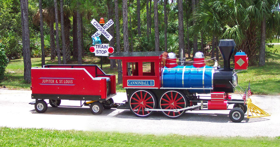
“In the 1950’s I grew up with a Lionel train table my dad built in the basement of our house in Berkley Michigan.
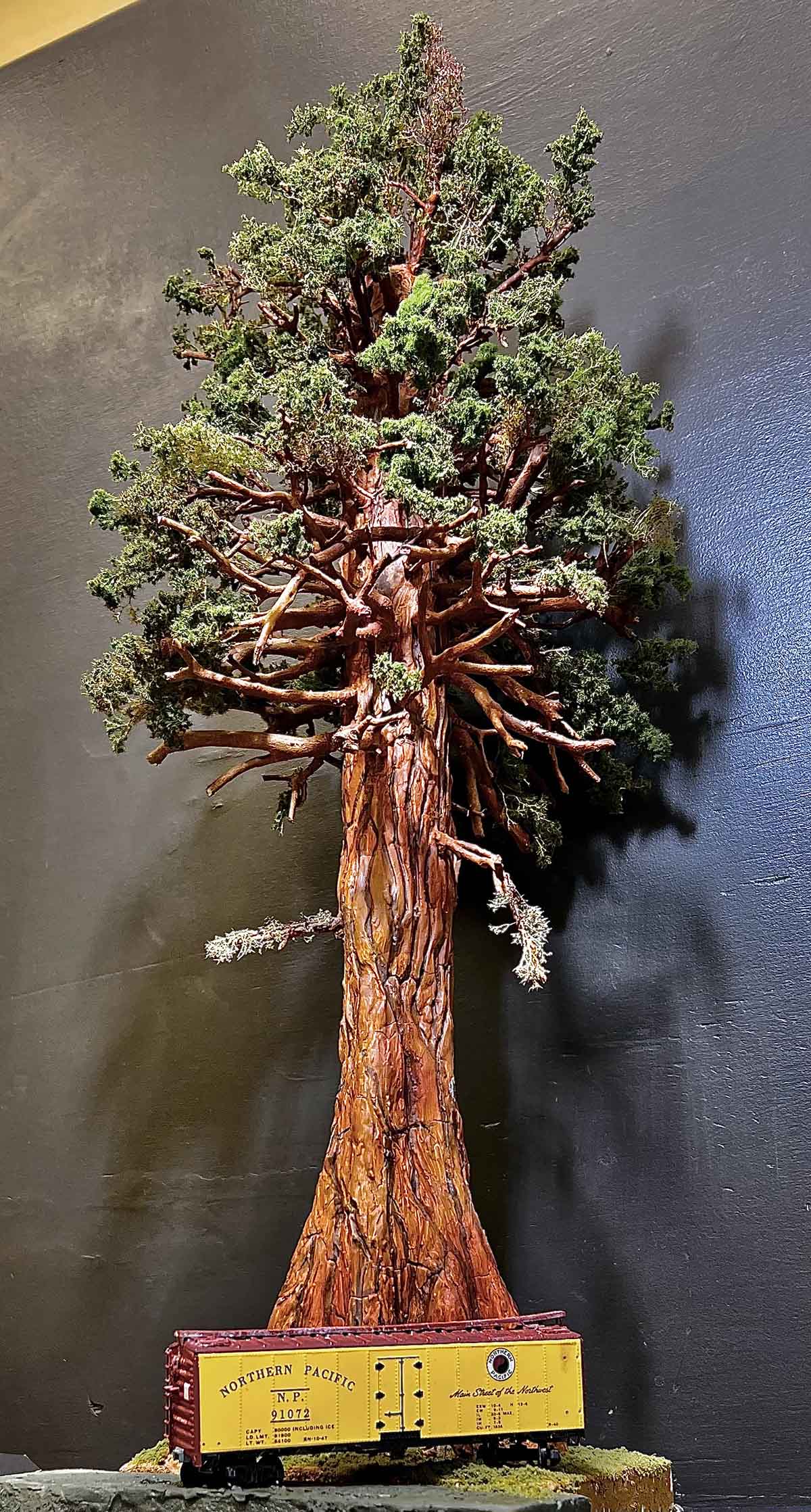
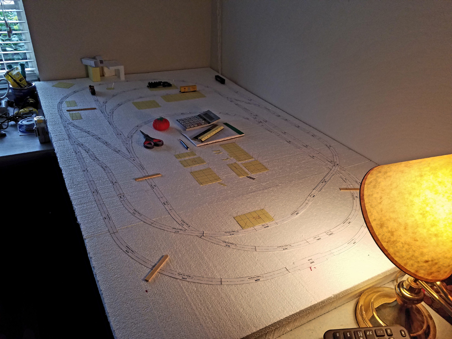
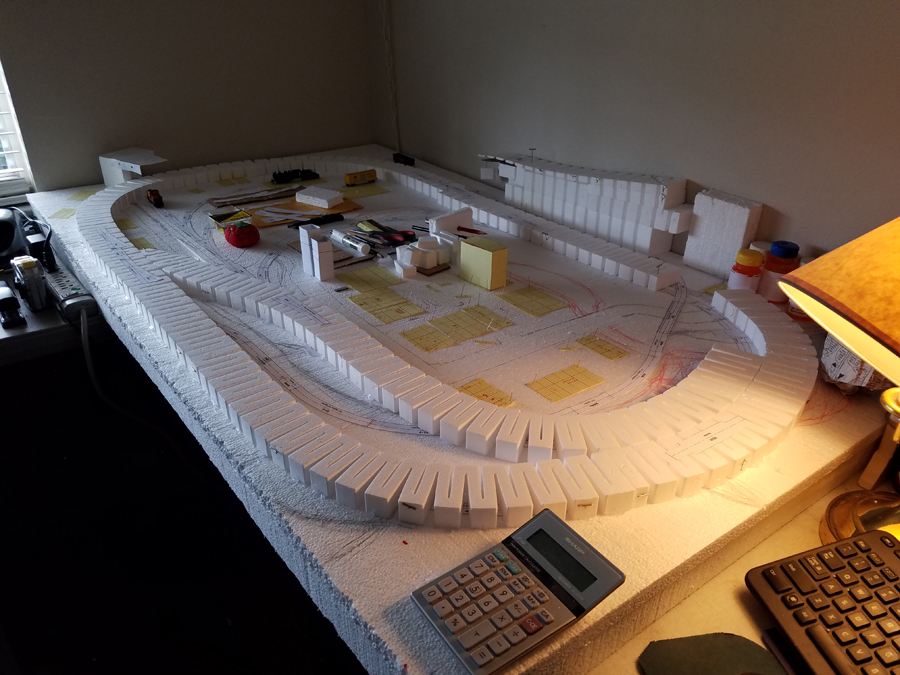
About a year ago I decided to build a N scale railroad in my house. I first had to do a lot of reading about the changes in model railroading from the 1950’s. DCC what a change from having to section off different areas of your layout. Also what materials are now available for landscaping from card stock buildings to ground cover.
THE THEME:
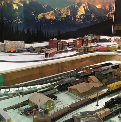
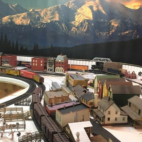
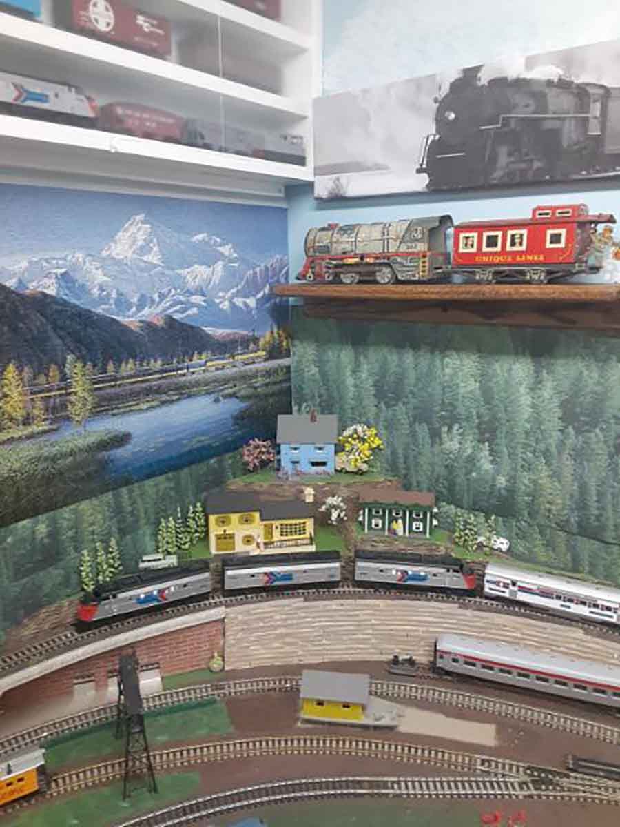
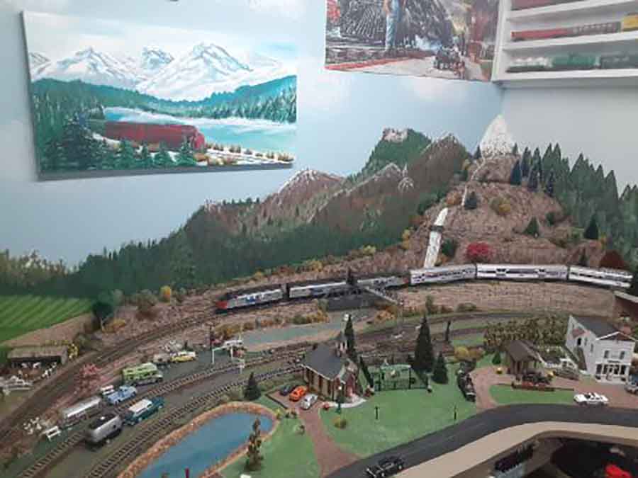
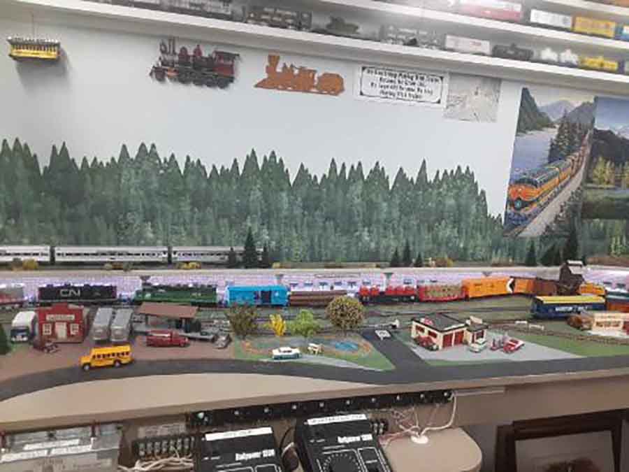
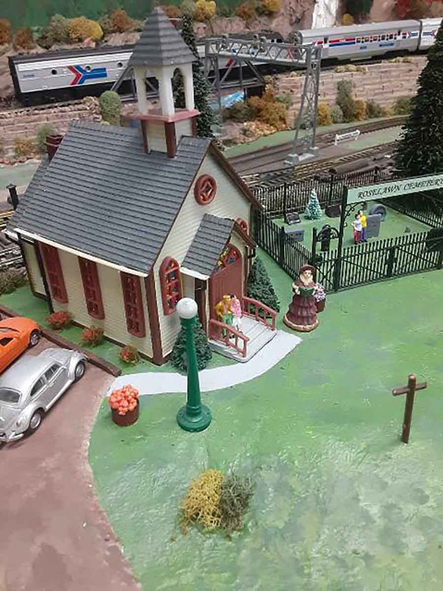
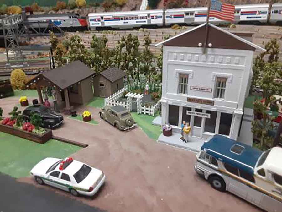
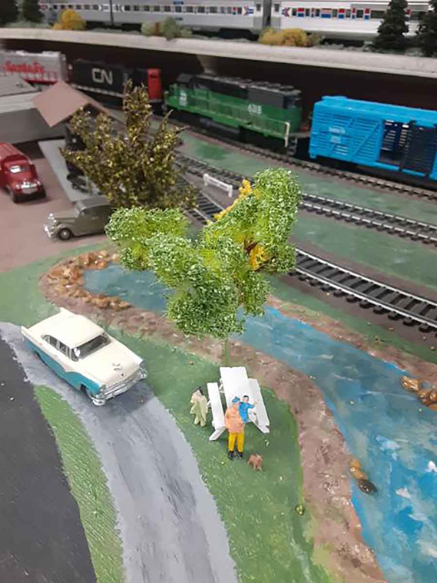
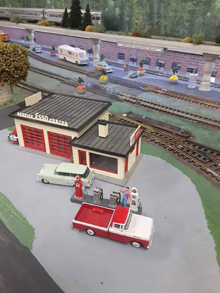
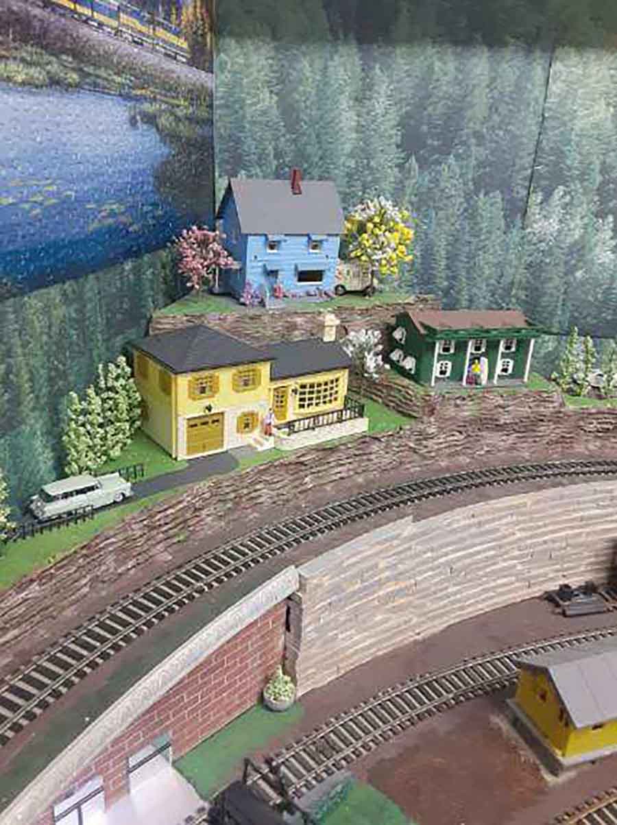
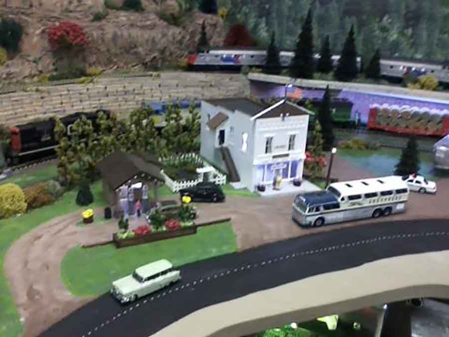
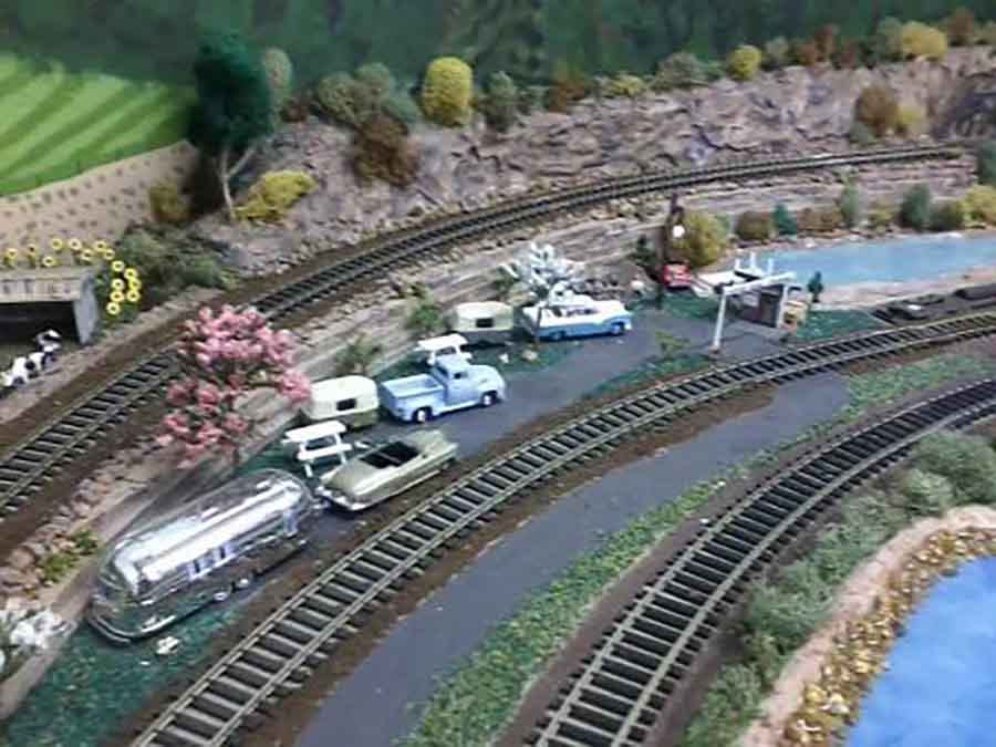
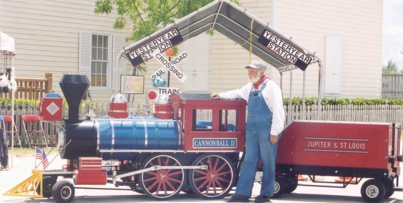
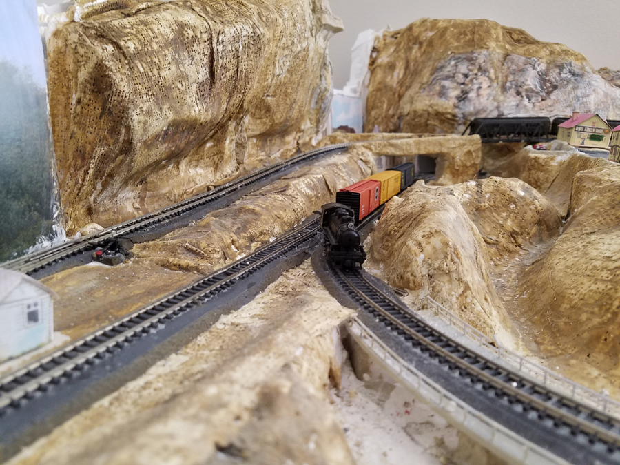
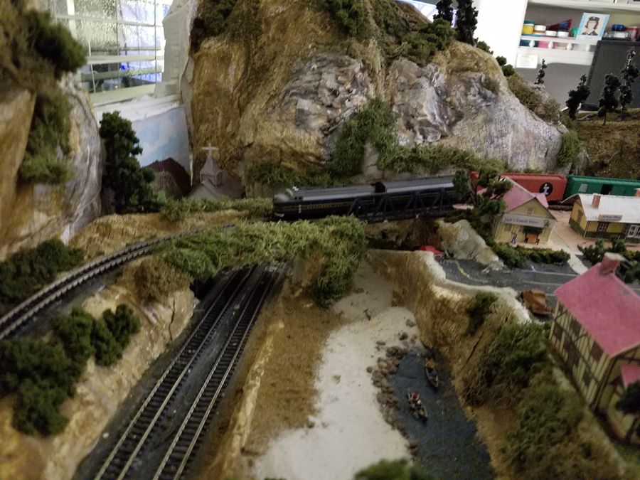
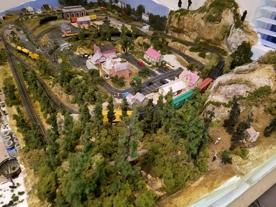
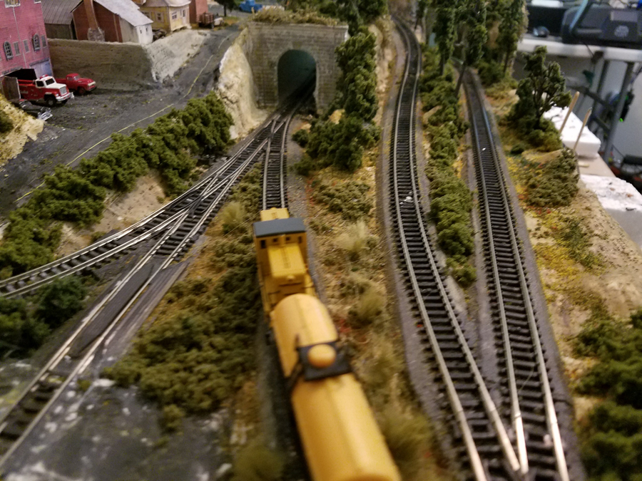
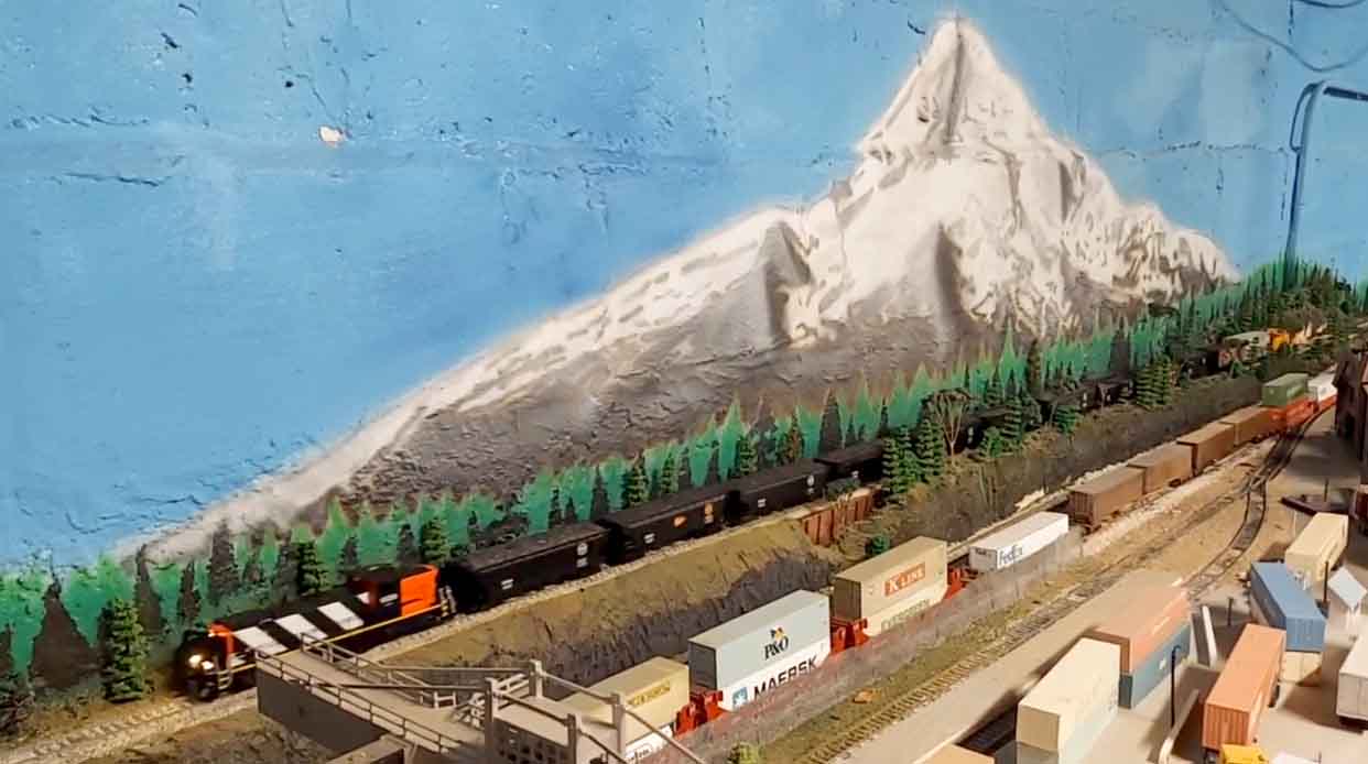
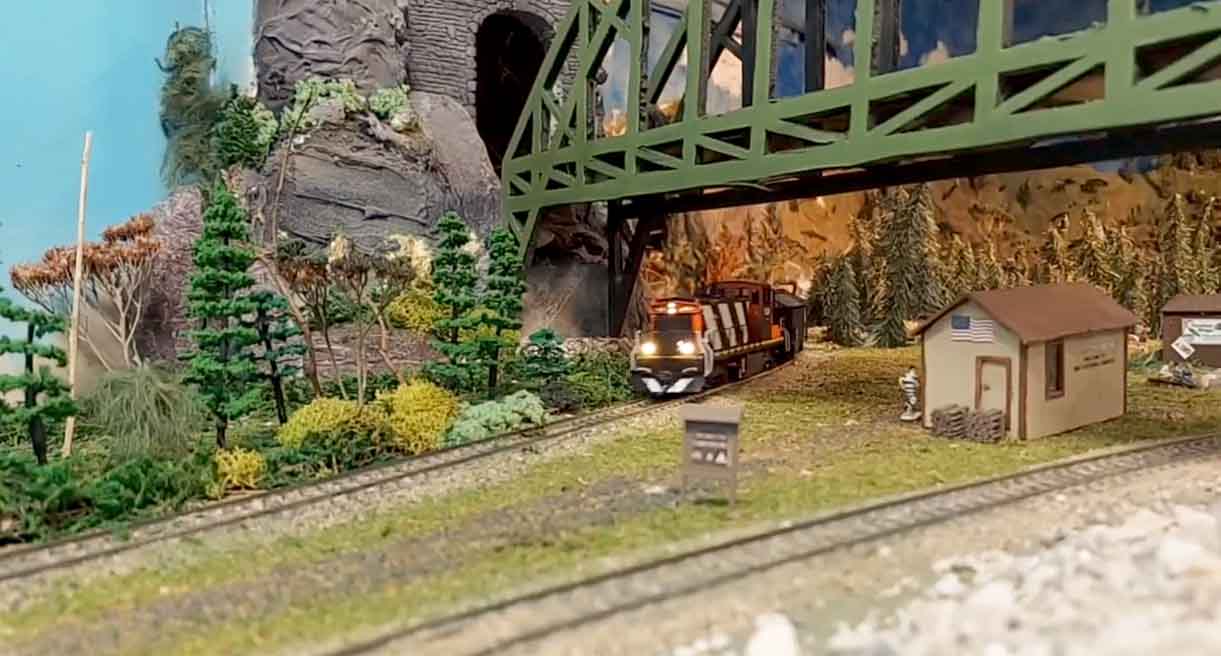
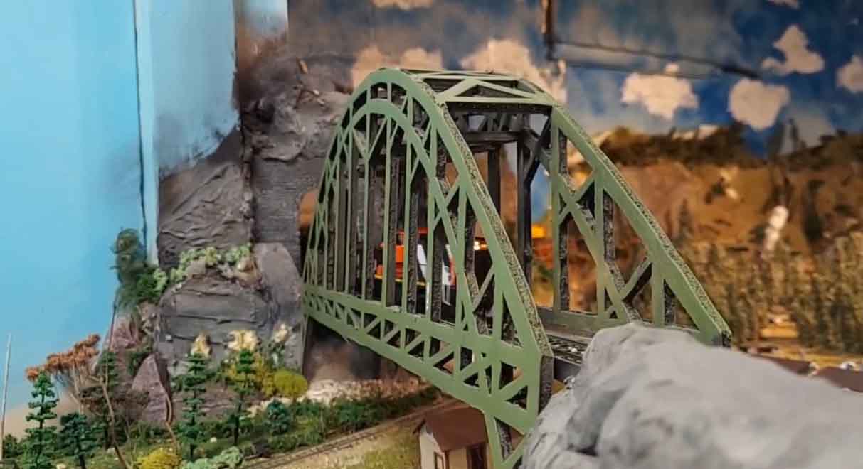
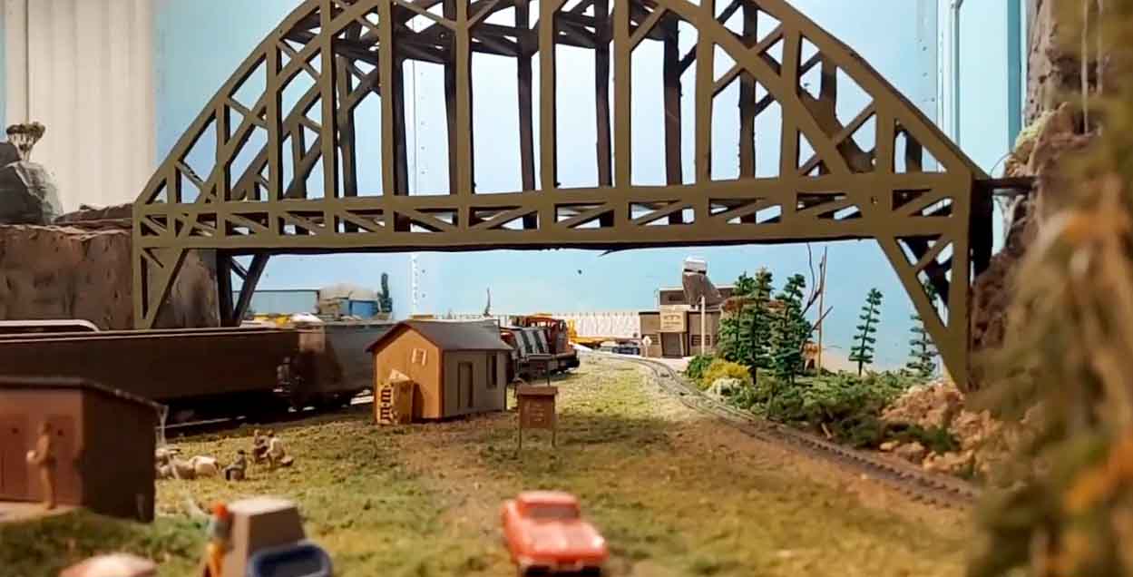
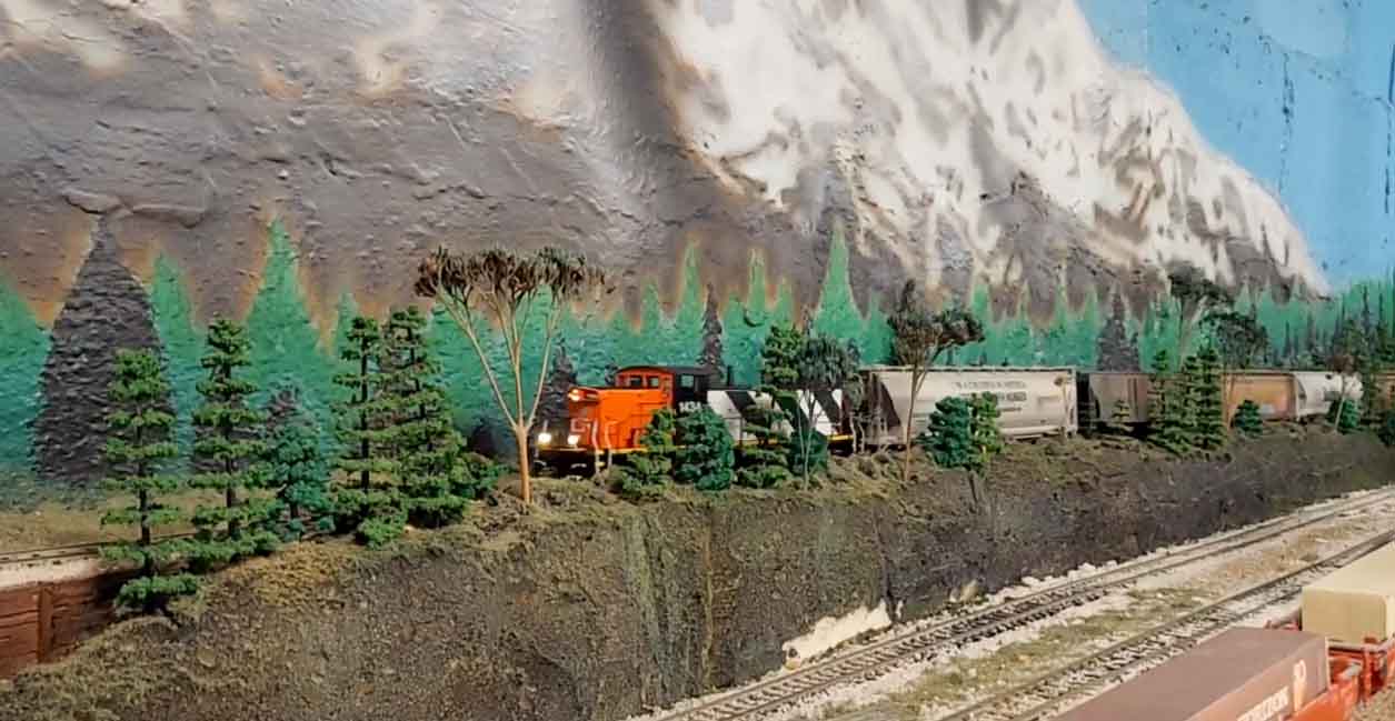
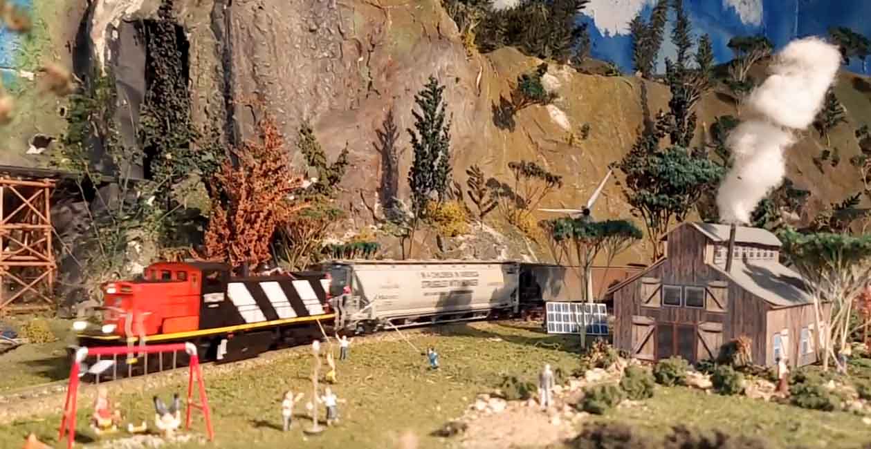
The theme of my railroad takes place in the early 1950’s on the Baltimore & Ohio rail line between Baltimore and Cincinnati. The village is in the mountains of West Virginia along Highway 50.
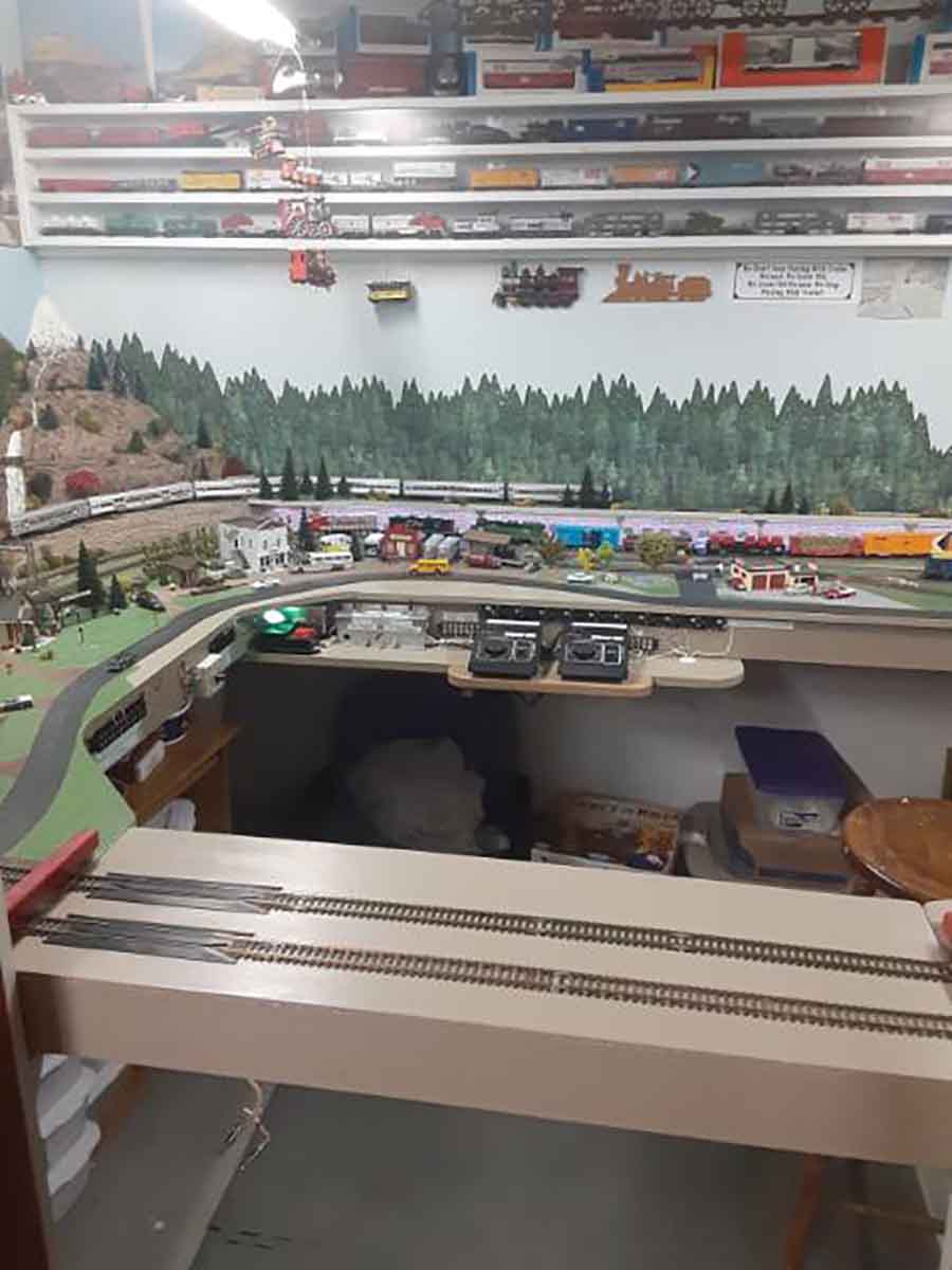
The main line along this route takes you through the mountains into the rolling farm lands of eastern Ohio. There are two spears one that will take you up into the village with a stop at the passenger depot. The second spear is to the local coal mines and trucking fright yard.
Tom”
Now on to Greg:
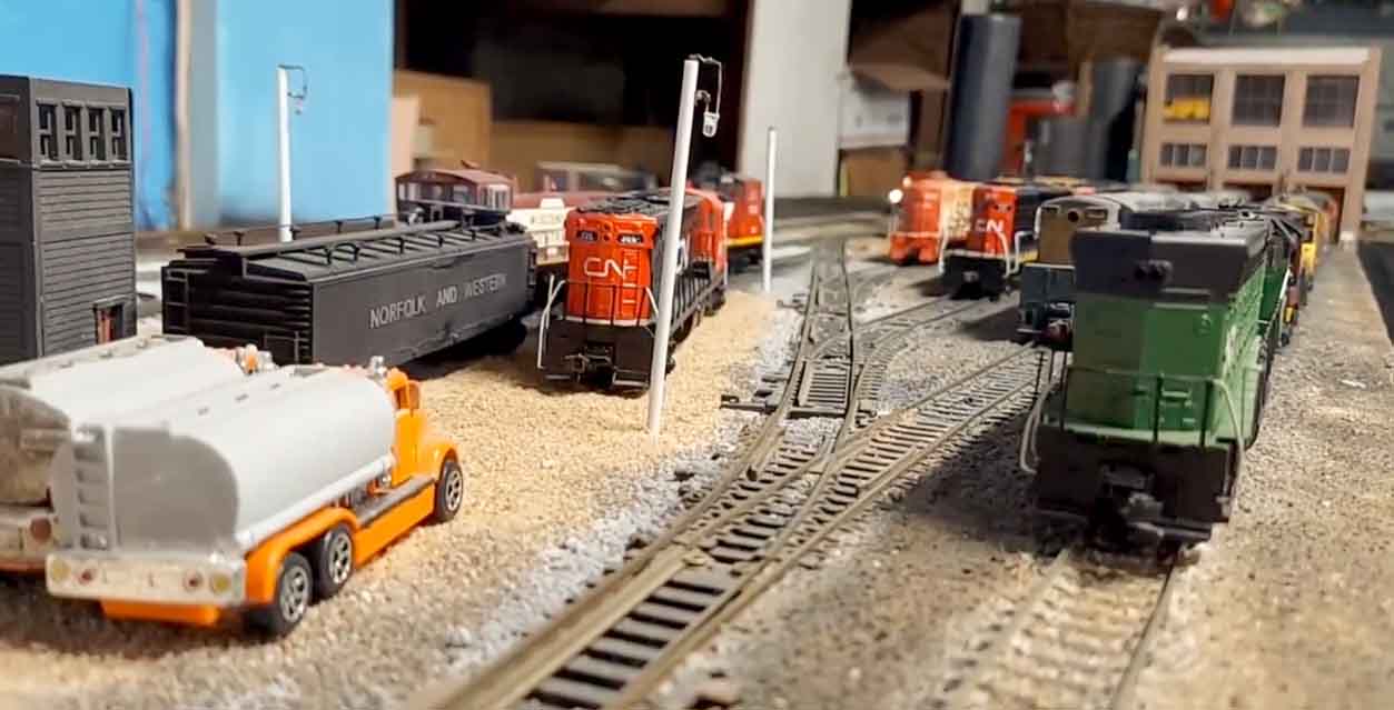
Greg’s been in touch with some fab pictures of his HO scale diesel locomotives.
But what I like best about his layout is not the locos, but how he’s picked his theme, and then how he’s made it personal.
Carry on reading and you’ll see what I mean:
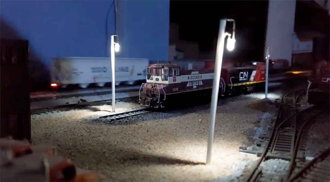
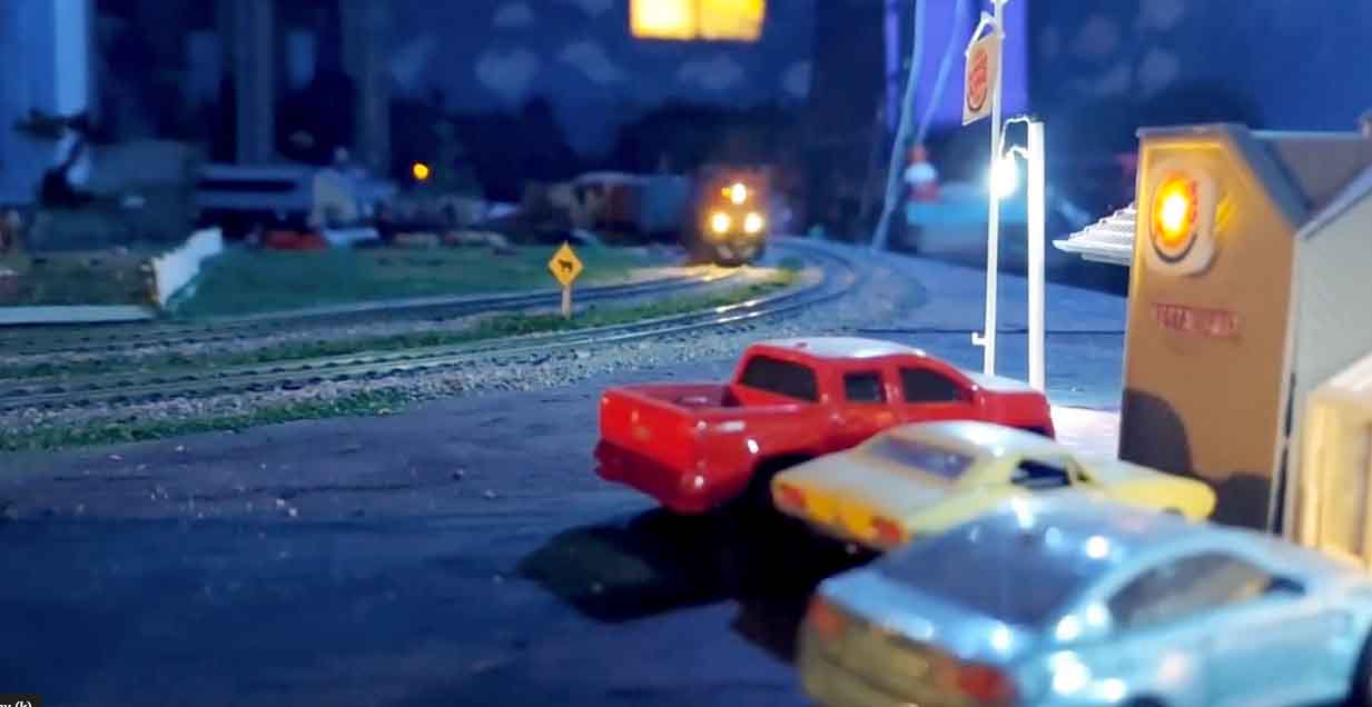
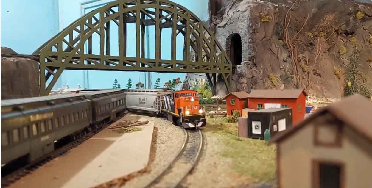
“My current layout is 26 foot by 18 foot modeled in HO scale. It is a DC layout.
My layout is a “living scrapbook” of my life. Several of my HO scale diesel locomotives are ones I either road/worked on when I worked for the railroad or ones I have seen in person.
I have done a lot of custom painting and detailing of my locomotives and rolling stock to bring the personal connections to them.
Several of my car and locomotives are numbered for friends and family, birthdates or anniversaries as the reporting numbers. Great way to make things mean more to me personally that way. It has a connection to me more than a store bought stock number.
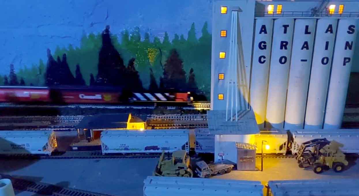
I have a nice mix of diesel locomotives as well as a few of the giant steam locomotives which allows me to enjoy a wide time frame of operations this way.
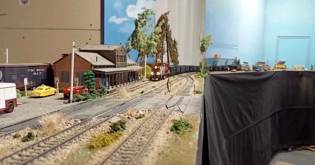
The layout is, as most of us model railroaders feel, a work in progress.
I’m still adding details to the scenery as well as more lighting for the night time effect. I’m already working on plans for a bigger layout when we move and have more space.
Greg”
A big thanks to Tom and Greg.
That’s all for today folks – please do keep ’em coming because I’m pretty much out of stuff now.
Dare I say it, but I might even have to put my feet up for a few days next week – it’s that quiet.
But if today is the day you stop dreaming and start doing, just like Tom and Greg, the Beginner’s Guide is here.
Best
Al
PS More HO scale train layouts here if that’s your thing.