How to install ho scale turnouts

Jim’s been in touch again – this time with how to install HO scale turnouts.

(his last missive is here).

“Hello Alastair

Jim from across the big pond here in Buffalo NY, and it has been a long time since giving any update on Starrpoint Railroad.

I have been converting the layout from DC to DCC operation. It has required a huge rewiring undertaking.

There is over 500 feet, of new wiring on the layout and there is more to do. From wiring all of the track points, the 18 tortouise switches, signaling all of the buildings with new LED or SMD lights in them. The LED’s need a resistor to control the voltage going to them while the SMD’s have resistors built into the light strip.

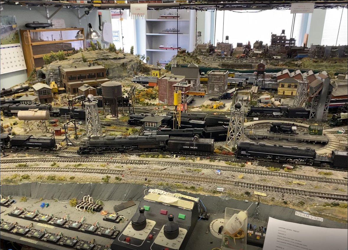
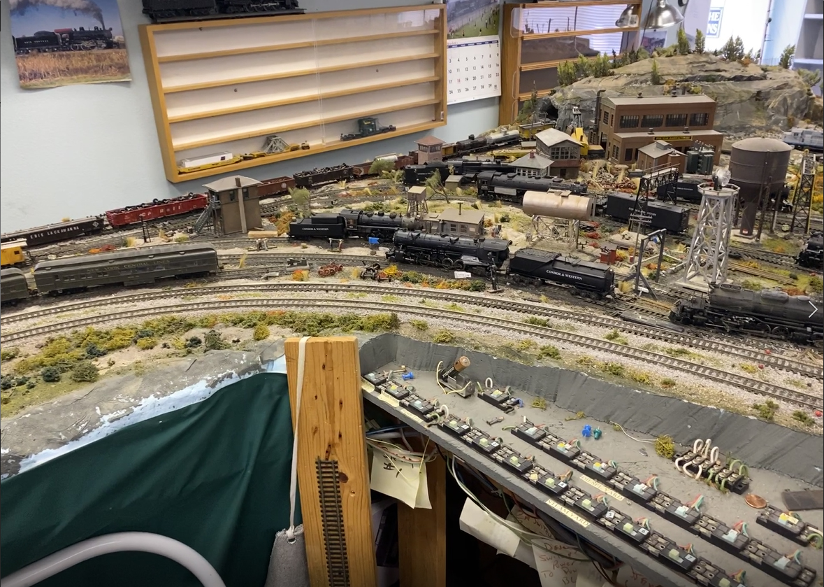
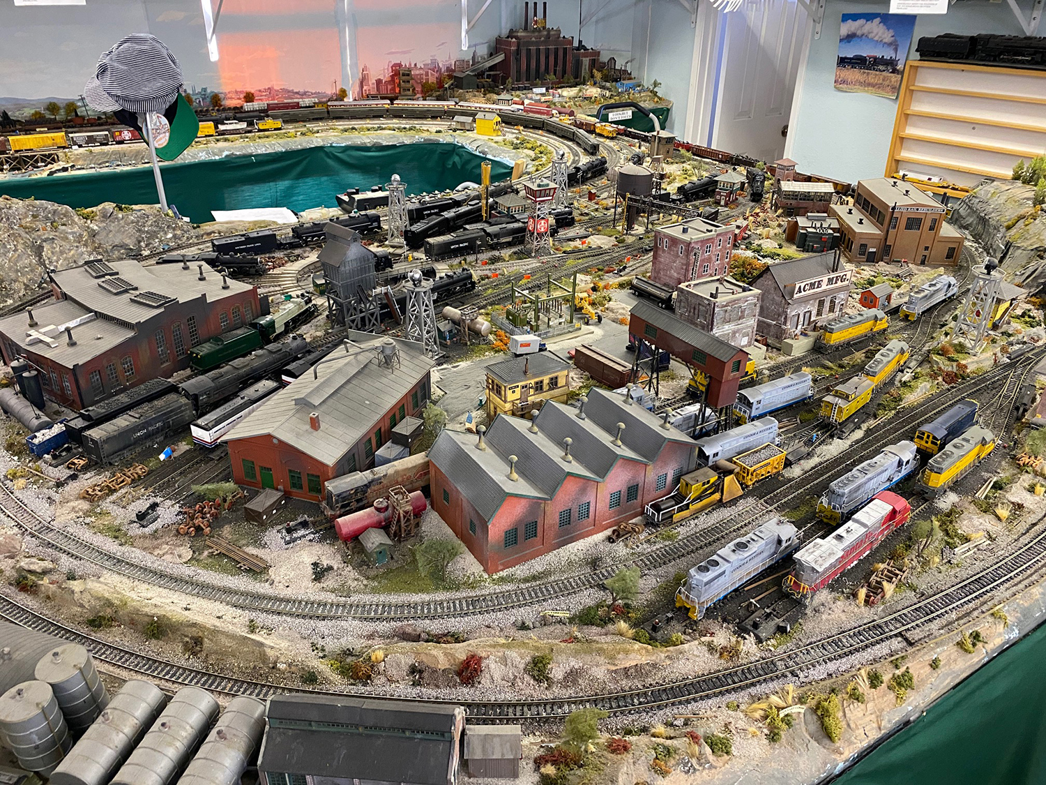
There is a diesel and a separate steam area on the layout. The Diesel side has a Walthers Transfer Table. It is an old version that Walthers had some years ago.

The electronics for the table stop working, so I had to find a way to make it work. The Electronic board controlled the lights and the movement of the table deck. And since there is no way of replacing the board, I had to come up with one, so I built a board that will handle the lights.

Here is a picture of the board that I built for the light issues:

wiring board model train

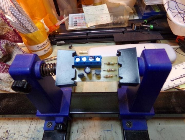
The board has wiring for the lights, and tracks. Since the old board was able to work a blinking light on the table to notify movement, I had to build the board with transistors to handle that part, and a part to handle all of the other lights.

For the transfer table to operate I found that a DC transformer will work to move the table back and forth, but will not automatically stop at a given point. I can stop the table, at the proper spot for track alignment. So that took care of the Transfer table operation and light issues.

In the Diesel Transfer Table section, there are 12 tracks leading to various points.

Three of the tracks for the Diesel House, three for the Car Shop, one track for the Maintenance Shop, Three tracks for Diesel holding and two tracks for the Diesel Refueling Station. All of these tracks had to be converted to DCC and controlled separately.

There is a 6 position Rotary Switch controlling these tracks. The Rotary Switch has two separate power connections that allows for 12 power feeds. This is accomplished using a Double Pole Toggle Switch ( position A and position B ) There are indicator LED’s showing which track is operating.

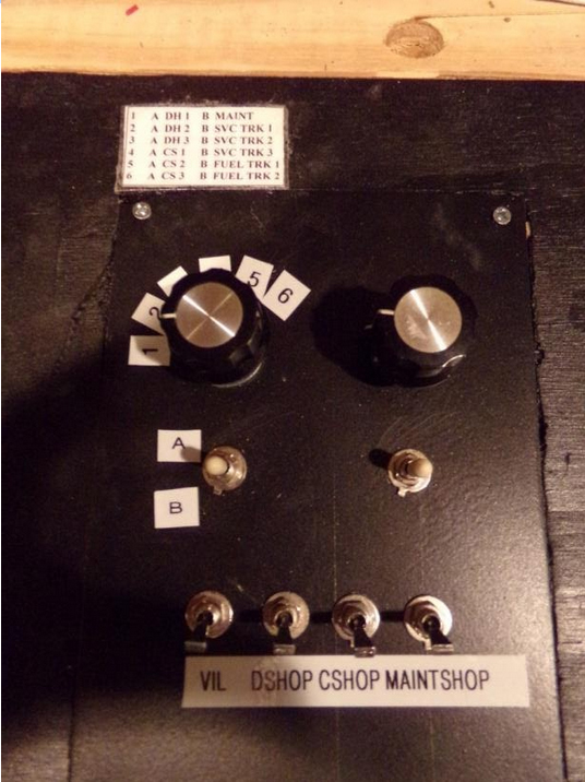
Here is a picture of the top of the main panel showing the rotary switch and control toggle. The left rotary switch is for the Diesel area. On the layout drawing I have placed LED’s to indicate which track is in use. The reason I did that, all of the Diesel Locomotives will have sound, and I did not want all of them to come on all at once, the noise level would be hard to handle.

control panel

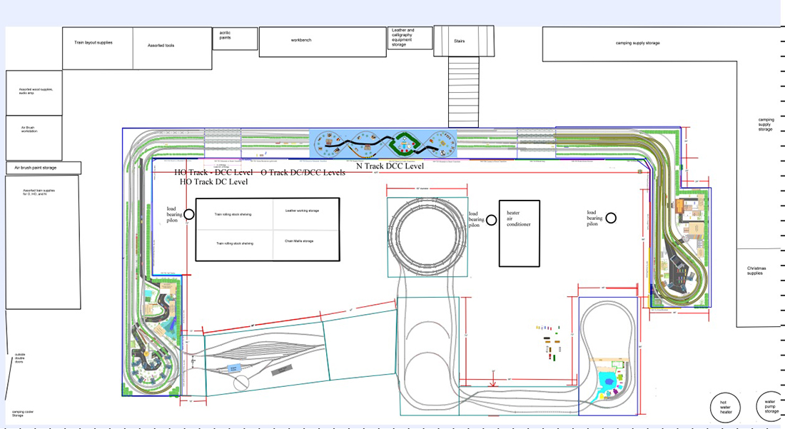
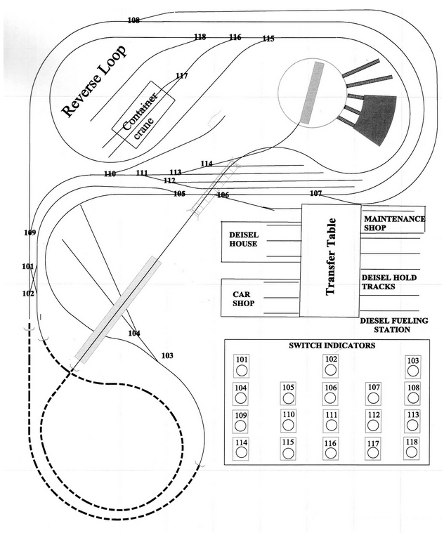
I made a drawing of the layout to indicate all of the turnouts. Since there are 18 HO scale turnouts I need a way to show the turnout position either open or closed. So on the drawing I added a SWITCH INDICATOR for the turnouts and numbered each turnout on the layout drawing.

Each one is a Bi-Colour LED ( RED / GREEN ). I installed 18 light tubes to hold the LED in place. Each of the indicator light centre’s had to be carefully cut out for the LED to show through. The Layout Drawing was LAMINATED to protect the drawing and to enhance the LED Light.

HO scale track plan

In order to have the Bi-Colour LED’s work correctly, they must be wired a specific way. Below are the items you need to complete this project.

wiring diagram

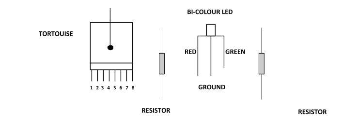
On the tortousie switch machine, there are 8 terminal points, 1 and 8 control the switch only. Terminal points 2 and 3 plus 6 and 7 are auxiliary terminal points.

Terminal points 4 and 5 are auxiliary power points. These two points can be used to supply power to signals, or track usage.

Here is how to wire the BI-COLOUR LED.

wiring diagram

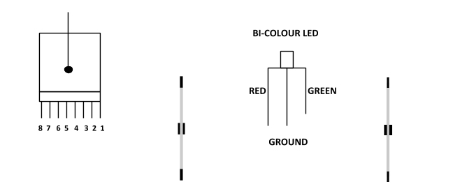
Take a DC power wire to power point 4

Take a wire from #3 to the resistor that will control the Red side and from the other end of the resistor to the Red side of the LED

Take a wire from #2 to the resistor that will control the Green Side and from the other end of the resistor to the Green side of the LED

The Ground part of the LED can be wired in series with other BI-COLOUR LED’s.

HO scale turnout wiring

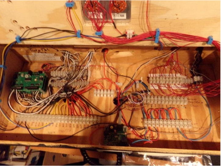
Below is a picture of the NCE SWITCH 8 MK 2 DCC boards. There are three of them that control the 18 turnouts. The boards are located in the upper left hand corner. The arrow below points to their location

HO scale turnout wiring

Here is a picture of the top of the Main Panel with the Switch Indicators

HO scale turnouts control

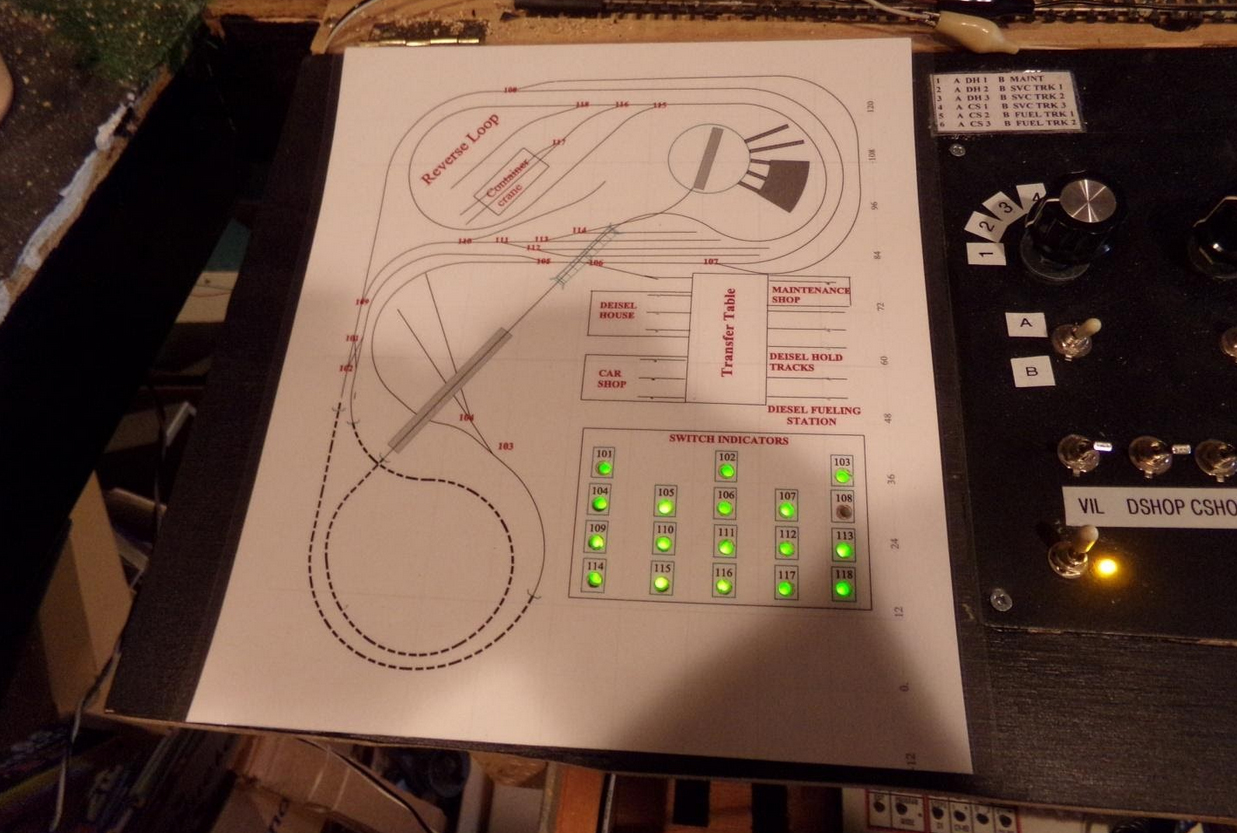
At the time when this picture was taken, turnout 108 had not been wired as yet. It is not wired for the panel. Turnout 108 has four functions: Control the turnout points, Indicate on the Main Panel, control the Signal Tower and Track Power.

The Signal Tower indicates which track is in operation beyond the turnout. All trains can enter the area that is controlled by the Signal Tower and will not continue past if the turnout is not aligned correctly.

Below is a picture of the Signal Tower.

signal tower

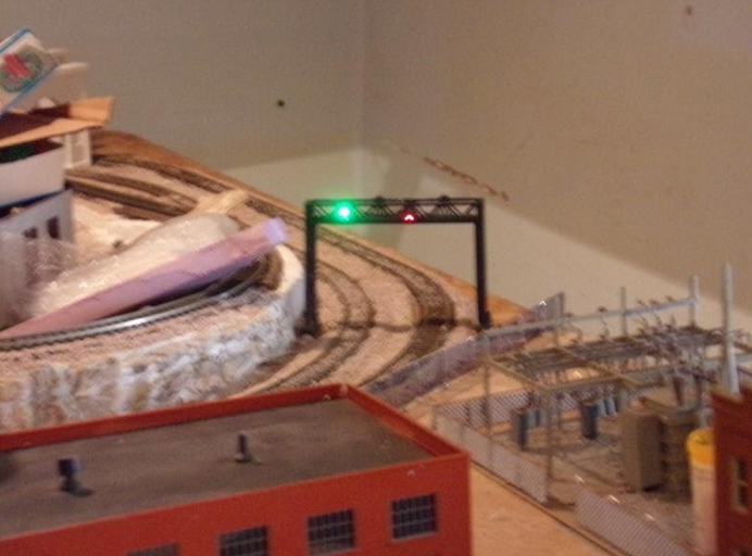
As you will notice, the track that has the Green Signal the train on that track can proceed past turnout 108, while a train entering on the outside track will stop at turnout 108 to prevent an accident. Once the turnout is set to the correct position on the outside track, then that train can proceed.

All of the above wiring took a long time to complete, but the work involved was worth it.

Most of the buildings have lights in them. On the panel that contains the two Rotary Switches, there are four toggles that control the Building lights. The one marked VIL controls all of the village and future city building lights.

The Toggles marked DSHOP control the Diesel house lights, C SHOP the car shop lights, and MAINT the maintenance shop lights. These lights can either be on all of the time or on only when being used.

I will be sending an update showing all of the building lights when they are lit. I want to complete the city portion of the layout first that will take some time.

I hope you enjoyed what has been completed so far.

Jim.”

A big thanks to Jim for taking the time to show us how to install HO scale turnouts.

In fact, there is another very good post on HO scale turnouts by Cameron:

Model railroad turnouts.

And if your trains stop on the turnouts, and it’s driving you mad, this post will help:

Capacitor for model trains.

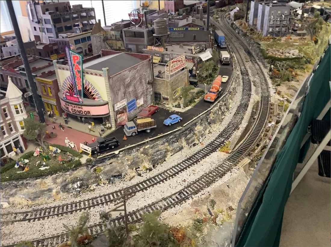
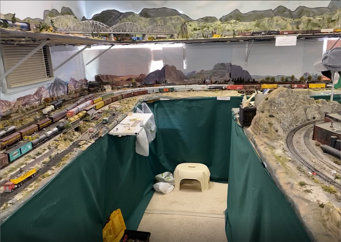
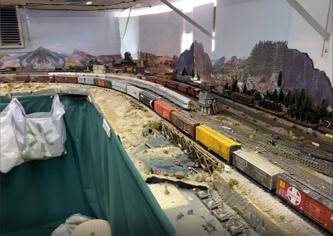
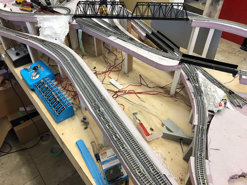
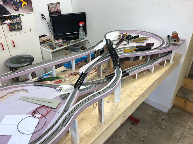
It’s always good to see a layout morph from a tangle of wires and plastercast to a scenic railroad scene (His first post is here).

That’s all for today folks.

Please do keep ’em coming.

And don’t forget the Beginner’s Guide is here if today is the day leap out of your armchair and start planning your masterpiece.

Best

Al

PPS More HO scale layouts here if that’s your thing.

HO scale double dog bone

Frank’s been in touch with his HO scale double dog bone layout:

“Originally my HO scale layout was located in a room I had a contractor build in our San Diego, California house attic.

As my layout inevitably grew, (evolved), I realized that the attic was too constraining. I raised the issue with my wife: “Should we move to a larger house or should I have a room built over our extended garage”. Her silent, cold, frozen stare told me that we were not moving.

Thus, I hired a contractor to build a room over our garage. What a problem! It took the contactor the better part of a year to demolish the entire two car garage which was attached to our home; drill down into the earth for earthquake proof construction, rebuild the garage, and over the new garage, construct the circa 30 by 30 foot model railroad room.

His comment: “All this for electric trains?”

Oh well.

Next I purchased an HO layout computer program and, on my desk-top computer, designed a modified HO scale double dog bone type layout with 48 inch diameter loops at each end.

I ordered and assembled about a “baker’s dozen” pre-fabricated tables; purchased boxes of 4 by 6 foot sheets of 2 inch thick, blue foam boards; boxes of HO scale flex track, boxes of cork track bed; scores of turn-outs, many boxes of track, additional transformers, rolls of various sized wires, etc. etc.

The blue foam was put over the plywood table tops but installed under the cork road bed for sound suppression. It works fine; except I had to buy a special very long drill to drill holes through the foam for track power leads. The thick form permitted cutting creeks and rivers that passed under the track, allowed for track adjacent elevated town streets, and for main-line track road-way “cuts and fills”.

Finally the hip-high, two main line, designed layout was up and running. But I wanted more trains running simultaneously. I then hired a contractor who installed a completely separate, eye level, 30 inches, and in places 48 inch wide shelf, around the layout room.

This shelf permits me to run four long freight trains on the eye level portion of the layout and two separate main line trains on the hip-high layout. Thus, now the layout will run 6 long trains simultaneously.

I like long trains, preferably freight trains of some 40 to 50 cars, snaking by parked fright cars and locomotives, across turn-outs, and through the country-side and towns. I have a built up town of some 35 or 40 structures/ buildings including various stores and a movie theater, which is reminiscent of, and named after the mid and late steam era city of Johnstown, (where the big flood occurred), Pennsylvania.

Is this it? Am I done, adding to or expanding the layout? Who knows?

Recently, my contractor quietly told me that to expand the current train room would require my wife, our dog, and me to move out of the house for about a year. NOTE: I am not dumb enough to raise this issue with my wife.

In building my layout I made every mistake in the book and scores that people never heard of.

Here are some random thoughts – suggestions – in no particular order:

Before beginning design for a new layout, determine if you love seeing long trains running, or if you prefer detail switching yards, and train “make up” activities. My layout has a plethora of yards, stub tracks, “Repair in Place” side tracks, and storage tracks, all wired up, but almost all of which I never use.

Don’t install track further away from you than ¾ of your arm’s reach. Don’t put track hidden behind buildings or scenery. Don’t put track in tunnels or mountains which have no “emergency” hand holes.

Don’t nail down or glue down track until you TWICE carefully go over it for vertical, horizontal and longitudinal alignments. Use a bubble level, to make sure the track rails are level with each other.

Repeatedly run you most de-railment prone locomotive in forward and reverse over your track before nailing or gluing it down.

Repeatedly run your most de-railment prone locomotive, forward and reverse over, through and across every turn out before nailing or gluing them in place. This is a great “pull you hair out” test for steam, 4-8-4’s and other locomotives with training trucks.

Don’t connect one piece of flex track to another section of flex track without carefully inspecting the connections for critical alignments; don’t install a turntable unless you provide for very long, straight, entry and exit tracks, half as long again as your longest locomotive.

Watch out when installing multiple interconnected sections of flex track on curves. You may end up with “locked-in” stresses which may cause the flex track and/or cork track bed to rise up and contort over time, particularly in a room that may be exposed to hot temperatures. If using white glue to fasten down track/cork road bed, try not to dilute the glue. That weakens the glue and may cause “Hold-down” problems.

Don’t buy “cheap” when buying track. Watch out for track profile dimensions and characteristics when mixing track manufacturer’s products. Don’t install a second main line paralleling an already installed main line without careful consideration of all potential obstructions, tunnel entrances; and “overhang” problems of long passenger cars and long locomotives.

Don’t over complicate, and crowd together installations of freight yards; stub tracks, and turnouts without careful consideration of necessary clearances and wiring problems.

Don’t run electrical supply wires without firmly taping a tag to each end showing where the power is coming from and where it is going.

Don’t install a shelf over your layout without appropriate lighting underneath.

Don’t inter-connect different radius turn-outs, or curved sectional track.

Don’t end up with more than one main, central, total layout control station.

Don’t end up with power transformers that are under-powered for the final electrical loads. It is wise to install “re-railer” track sections in line with turn-outs, tight curves, entrances/exits to tunnels or difficult to reach track work.

Try to have “walking access” to each side or end of your layout surface. I’m old and it really is a “Pain” to get down on my knees and crawl under the layout tables.

Railroad room: Make sure you have sufficient lighting for detailed work as well as when having guests.

Air condition the room, if possible. Watch out for aisle widths: The aisle widths in my layout room are, in places 26 inches wide – too narrow; and other areas 36 inches which is just enough for people to pass each other. Don’t have power cords on the floor of the layout room even when covered with power cord safety covers.

Try to have an adjacent space and workbench for a repair/build/ inspection area with table lighting, and space for a wide assortment of tools, glues/lubricants, etc. My railroad room has a
very convenient, and necessary, attached restroom.

Currently, my layout includes some 100 structures, many of which are illuminated. I have some 26 steam locomotives, from 4-8-8-4’s to 0-6-0’s and circa 35 diesel locomotives; 5 different complete passenger car sets and well over one hundred freight cars – bottom line: ”Too much stuff”

Frank

San Diego, California”

HO scale double dog bone by roadside

HO scale double dog bone outside loop

HO scale double dog bone overhead view control panel


HO scale

HO scale double dog bone with stean trains

HO scale double dog bone freight

HO scale double dog bone freight

model railroad

model railroad

A huge thanks to Frank for sharing his HO scale double dog bone layout – great pics and what a narrative too.

I did enjoy his list of things not to do.

That’s all for this time, folks.

Please do keep ’em coming.

And don’t forget, the Beginner’s Guide is here if today is the day you stop dreaming and start doing.

Best

Al

PS Latest ebay cheat sheet is here.

PPS More HO scale train layouts here if that’s your thing.


HO scale Dairy Queen

Bob’s been back in touch with his HO scale Dairy Queen.

(his last post is here).

“Al,

Here is another kit bash for you.

When I was growing up in the 50s my friends and I would bike about a mile to a soft ice cream store named Dairy Doll.

I had a small space on the layout that was begging for attention so I purchased a plasticville soft serve. It was all one color except for the roof. I painted it using several colors then I tried several sign colors.

I installed lights on the roof and in the roof overhang.

Then I purchased a HO scale Dairy Queen whistle which was a hand out years ago. I installed a slow RPM motor upside down in the roof. It has an 1 1/4 inch shaft that I inserted into the cone and glued it in.

I added chocolate stripes to the ice cream. I put in some patrons and some of my 50s cars. I also added some bicycles since the pictures were taken. The video shows the finished scene.

Bob”

HO scale diary queen

Bob’s HO scale Dairy Queen build put a smile on my face – I loved it.

“Hi AL;

I’ve been reading and enjoying your posts for several years. Finally decided to submit my first post – of a post.

I can’t take credit for the idea, I just put my twist on it.

Looking to add turnout #s to our N scale layout and saw the idea to use ends of popsicle sticks painted white to simulate mileage posts.

Instead of gluing them, I hot-glued a pin on the back so I could move then easily. Then I painted and attached printed labels so the numbers would look better than my writing.

Additional option. I have several turnouts that need to be thrown “together” i.e. a crossing.

For these, I add red underline markings noting that they are part of a group & then a number stripe on top giving them individual IDs within the group, (I, II, etc.

This labeling is repeated under the layout to also give each wire a unique code.

Thank you for providing this site so we can all enjoy the hobby better.

The best to you.

JB & Judy – Illinois, U.S.A.”

“Hi Al.

Quick note from another new guy. Long story short.

Worked in a hobby shop as a teenager and loved all of it but the trains stayed with me.

First Lionel as a kid then HO in high school and in and out of it till a few months ago when the isolation began because of the dangers of the virus.

Jumped into N gauge because I could do a door sized layout in the corner of my shop that is normally full of old Brit sports cars (have about ten of them) mainly MGs but just about all of the 50’s and 60’s over the years and that’s a lot of years as I’m now 82 but still kicking.

Railroad wise I’m well along with my mountain style layout with a lot of scenery in that little space.

Keep up the good work. I enjoy the variety of projects on your site.

Best regards to you and fellow enthusiasts.

James”

“Al

This is a thank you to you and John for all that you have done for everyone.

I started an O scale extension to my layout. The first picture is a pictorial of my basement.

The colored section is the new layout, at 19 inches off the floor. Projected for the future, the HO layout will be above it at 38 inches with the N track (in blue) at 48 inches. I used AnyRail 6 software program to build the design. Sorry if the picture is a bit busy but I have all the layers displayed. I found the software very easy to get familiar with and to use.

But this post is about the buildings going onto the bottom layout instead. ALL the buildings on this layout have been and shall be from your printouts. I have presently built 31 different buildings plus the embankment for the raised section. I am using John’s techniques with a few changes.

I knew I was going to be building a lot of buildings. With the virus causing everything to be closed (craft stores), here in Virginia, and knowing I wasn’t going to eat that much cereal I needed something else for backing.

Wandering the local hardware store (Lowe’s) I found the Ram Board in the carpet area for $30. A soft fiber board that is 36 feet by 3 feet and about one eight thick. Very easy to cut with an craft knife.

My printer is such that I could do the enlargement for O scale as per your recommendation in your Hints document. I cut all the printouts so that I could connect them so that front, back, and sides were separate complete items. The next picture is the only exception.

The printouts are glued to the board with Elmer’s white glue and when dried (under a heavy book, Thanks John) all the excess board is sliced away. It took a couple of hours to ensure full drying (because of the fiber board) and to ensure all pieces were properly flat.

Then copied the outline of the selected items onto another piece of the board and cut out the items again, as shown. This ensured that they will be recessed. Because the items were cut out, they needed backing, as shown in the next picture. But in the meantime, the original piece had all the cut edges painted the similar color as the front edges (thanks John). Once assembled the windows were properly recessed.

On another print out of the same building I used the same technique to cut out the frames to the door and windows, as displayed. The following picture shows the window and door frames positive on the building and the windows negative to the building.

The next picture shows where I assembled the separate pieces one corner at a time. Giving me a good solid 90-degree angle on each corner. The angle iron is 2-inch aluminum angle (3 feet at the same hardware store for $4) cut to 10-inch lengths. After assembly I realized I forgot to paint the sides of the window and door frames.

The next picture shows one side of the finished product. The last picture is the house that took the longest time. The windows are recessed and the building is recessed to all the black trim. Cutting out all the black trim was a real test of patience.

After 31 buildings the cost per building is less then $10. Al’s original print out (if bought separately and not part of a special sale) + nothing for multiple reprints + about two feet of Ram Board + the white glue + a couple of ‘snap off’ blades (to keep the points sharp) + LOTS of patience, for each building.

Worst case = 31 buildings at $10 is $310. At my local train shop the respective size buildings run from about $60 to $150. Average case = 31 buildings at $100 comes to $3,100. After placing the finished items on the layout it looks like I should build a few more of some that I have already built (maybe with a few alterations using John’s ideas).

Thank you, Al and John. And yes, coffee before I start in the morning and a glass of WHITE wine after six in the evening.

Lawrence”

A big thanks to Bob for sharing his HO scale Dairy Queen build, Jb, James and Lawrence.

Lawrence really does show you can pretty much build anything out of the print out scenery – I think that’s the fun of it.

That’s all for today folks.

Please do keep ’em coming.

And please don’t forget the Beginner’s Guide if you want to make your start without any of the usual mistakes.

Best

Al

PS Latest ebay cheat sheet is here.