Dean’s been back in touch with some more N scale scenery ideas.
Every time he lands in my inbox, his layouts and scenery just get better and better:
“Al, it’s been a while since I’ve updated everyone on progress on my Santa Fe Northern Railroad N Scale layout as my life got too busy. Over the last couple months, I’ve been updating the scenery and here’s some recent progress.
I’m trying to model the area around my house which is a little different from other parts of the country—dry with little growth except for scrub foliage and dried grass plus Piñon and Juniper trees at lower altitudes with pine trees at higher.
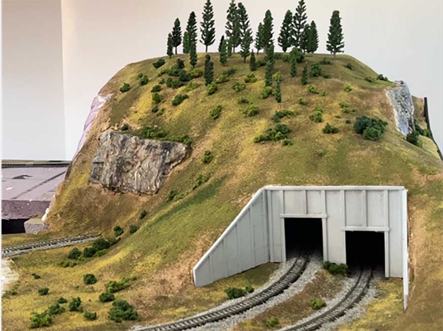
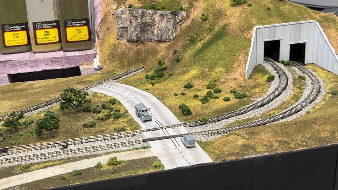
The first photo shows a mountain that I built with excess blocks of 2 inch foam covered with plaster cloth and drywall compound, then painted with my standard brown base paint.
After that I used my usual Woodland Scenics ground cover fine turfs (Earth, Burnt Grass, Yellow Grass, Light Green) and clump foliage (Light Green, Medium Green) for small bushes and trees,
The pine trees on the mountain are from Fazhbary (Amazon) and came in a bag with 44 pieces of model trees, 1.4 – 5.9 inch. Since the largest one were too big for N Scale, I cut off the tops to put in this part of the layout. I covered making and coloring rock formations earlier. When done, the mountain looked like the first photo. Since the tunnel portals had to be custom size, I designed them and printed them with PLA on my 3D printer.
Here’s another view. I printed out the roads on paper then glued the finished road pieces to 2mm Foam Paper
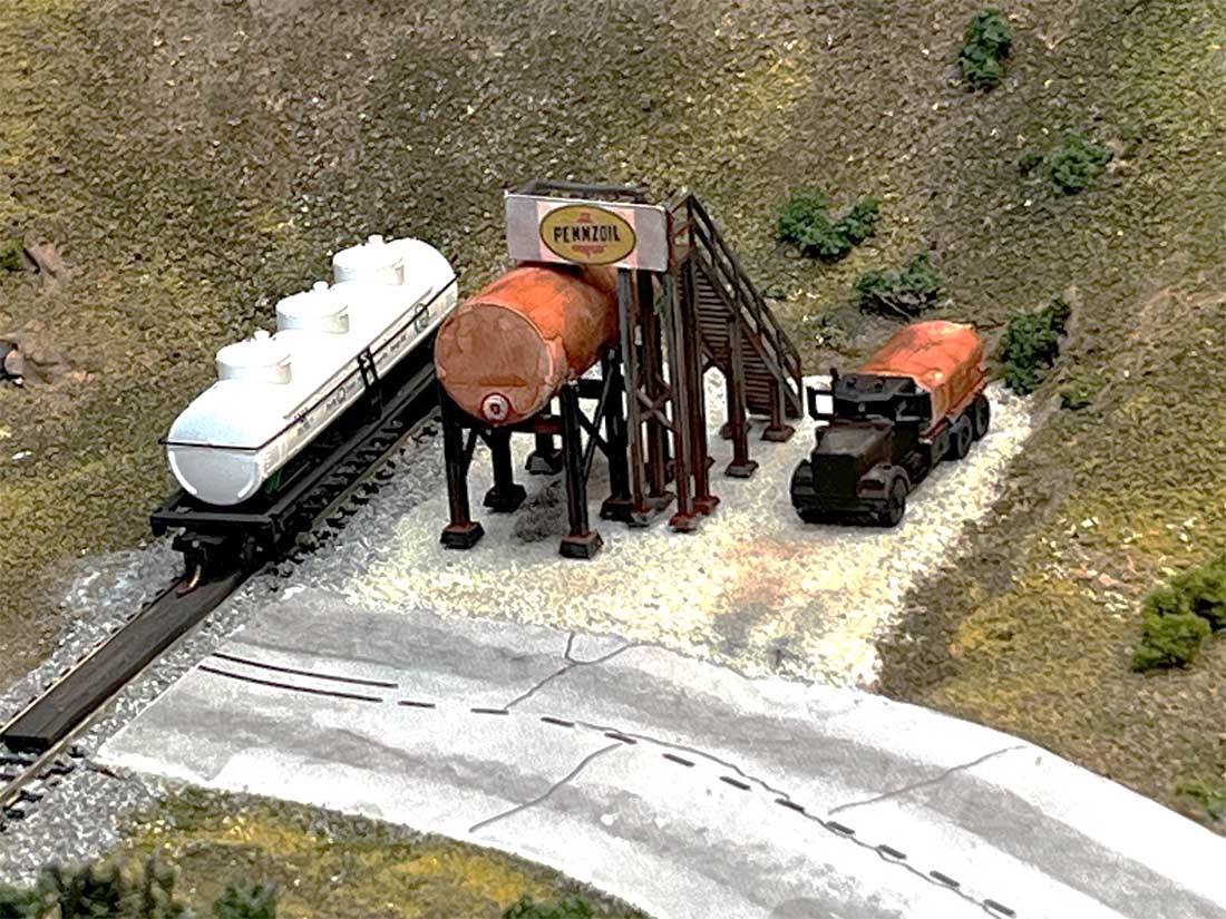
Here’s a model industry fuel tank and truck from Whistle Stop Models. I found the Pennzoil Logo on the web
At this point I wanted to model a gully in the low area between the two levels and road going up from the lower level to the higher mountain level, which is actually 2” above the lower level. I use 2” construction foam as a base for all the layout.
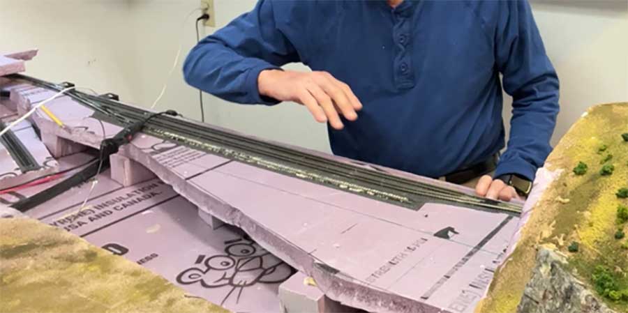
First I trimmed the edges of the foam board and cut a piece to support a new road between the levels. The slashes were cut at two places to allow the foam to bend, then the piece was pinned and glued with hot glue. The support structure was finished at this point.
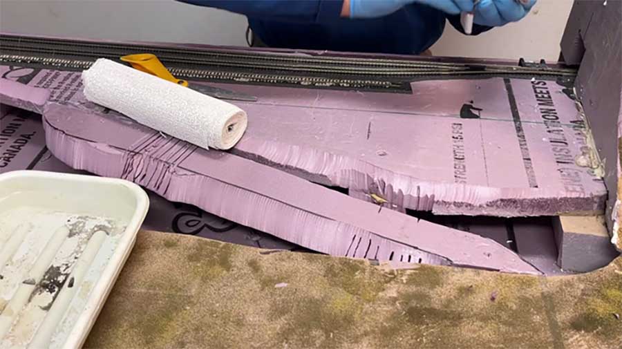
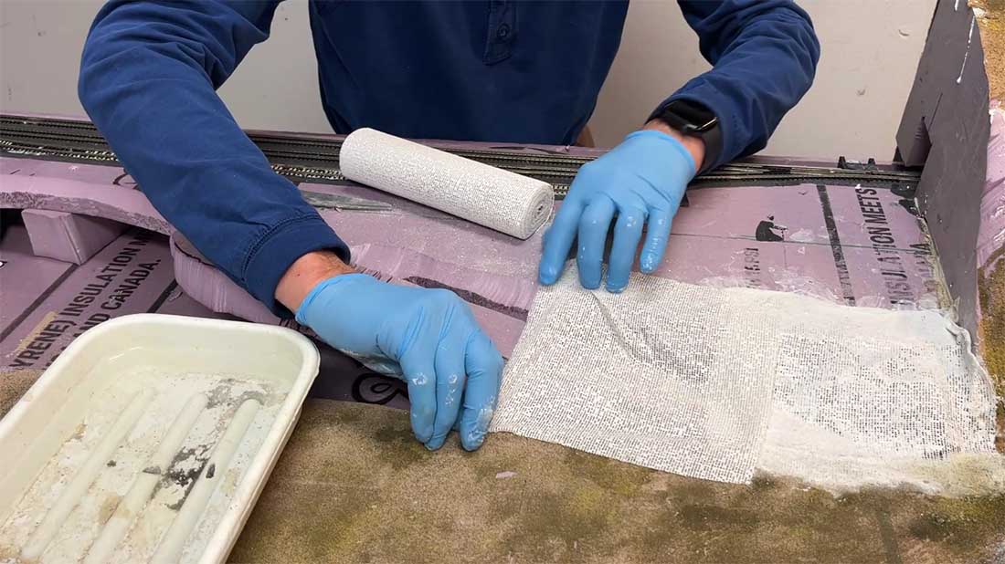
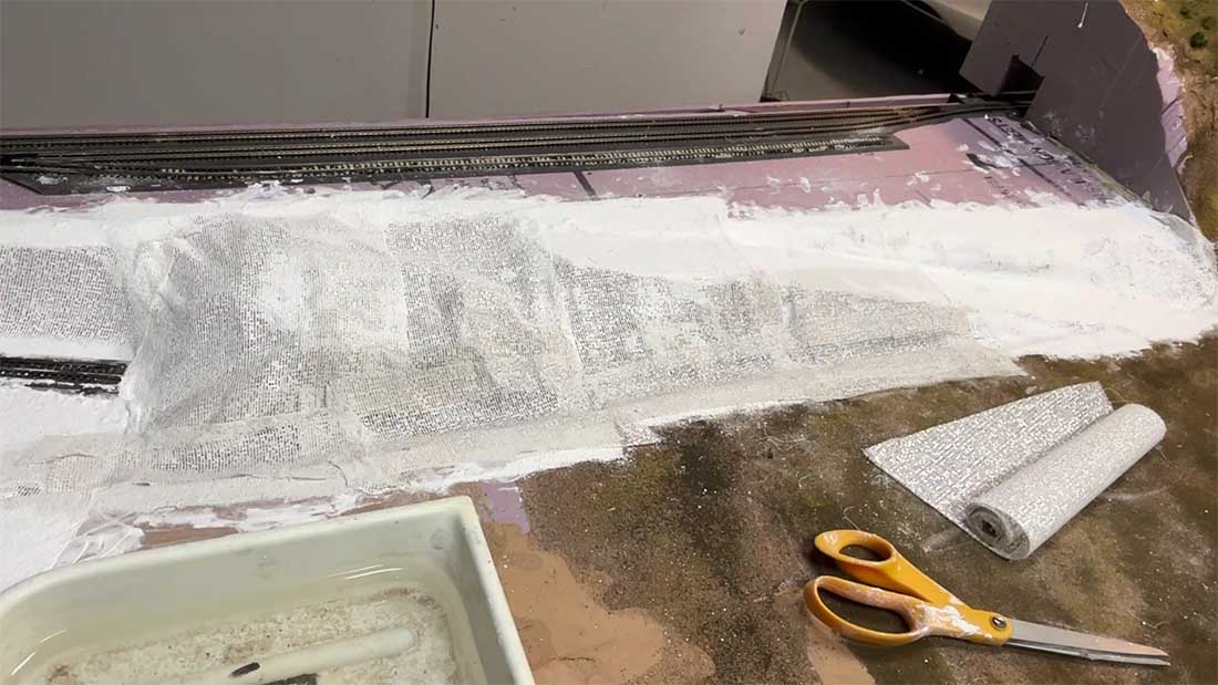
Then I covered the area with plaster cloth (next two photos)
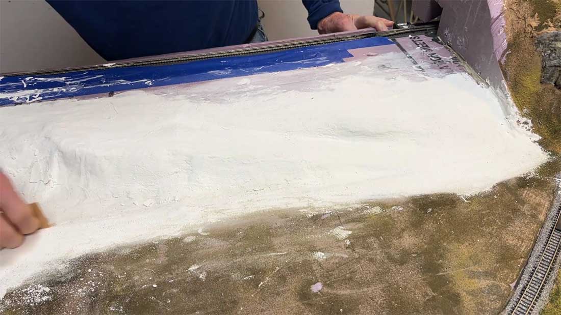
After the cloth had set up, I smoothed on wall board joint compound then sanded it smooth where needed
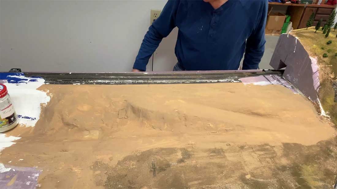
Here’s what it looked like after painting my standard brown base color.
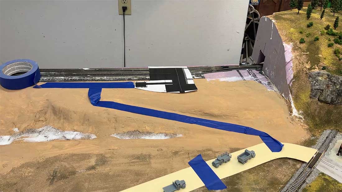
I built up the dry wash gully area (arroyo) with fine sand wet with diluted while glue and marked off where I wanted the gravel road to go with blue tape. The yellow paper is cut lengths of card stock which form the patterns for continuing the road. The black area on the paper on the above level indicates where I’m going to put a coal mine using a Walthers Diamond Mine kit that I’m working on.
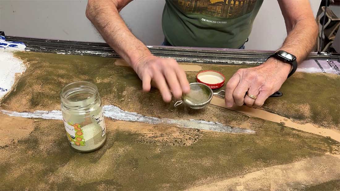
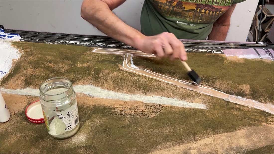
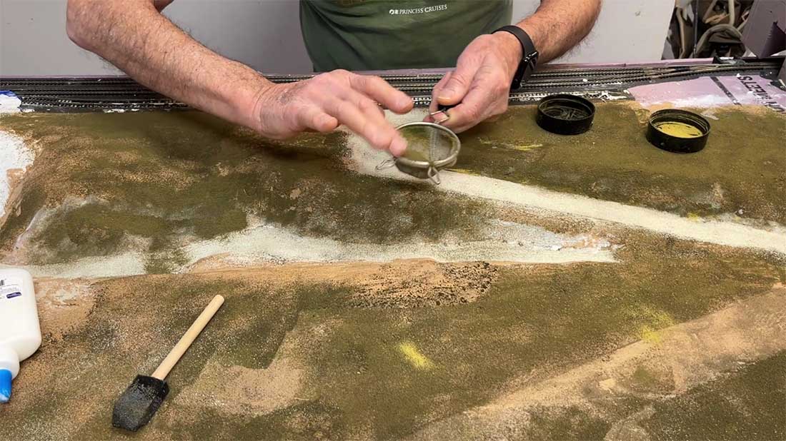
At this point I finished the area with various fine turfs sprinkled on thinned white glue. Next, I finished the gravel dry wash (arroyo) and the gravel road from the upper to the lower level by painting on full strength white glue then sprinkling on Woodland Scenics gravel (a very fine material). Next two photos
Final finishing of the scenery. Next two photos.
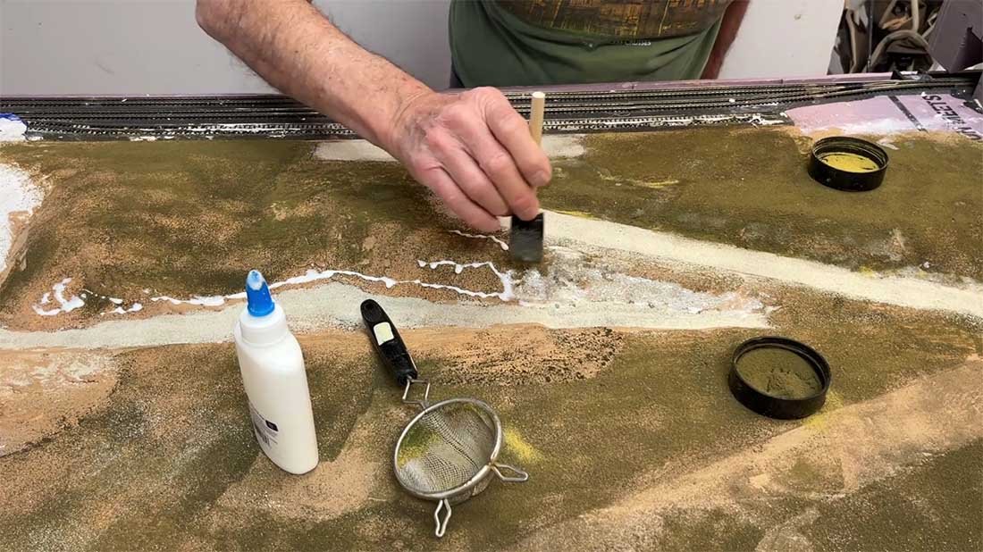
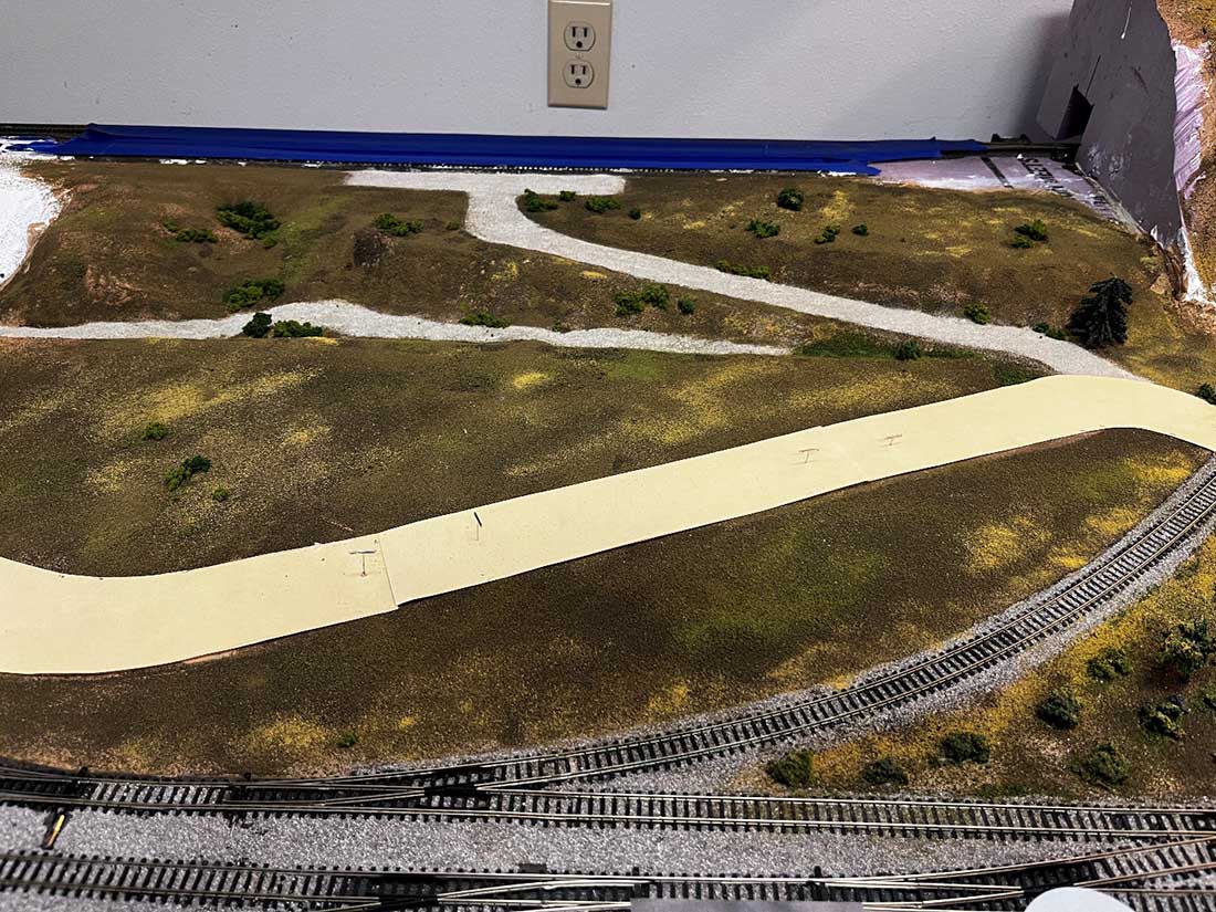
So, here’s what the area looks like now. I’ve started to add clump foliage for small trees and bushes
Thanks to all of you for your continued interest and comments. Let me know if there is more info you would like to see on what I’ve done here.
Dean from New Mexico”
A big thanks to Dean for sharing his N scale scenery ideas – I’m already looking forward to his next update.
That’s all for this time folks.
Please do keep ’em coming.
And if you think everyone else is having all the fun, the Beginner’s Guide is here.
Best
Al
PS More HO scale train layouts here if that’s your thing.
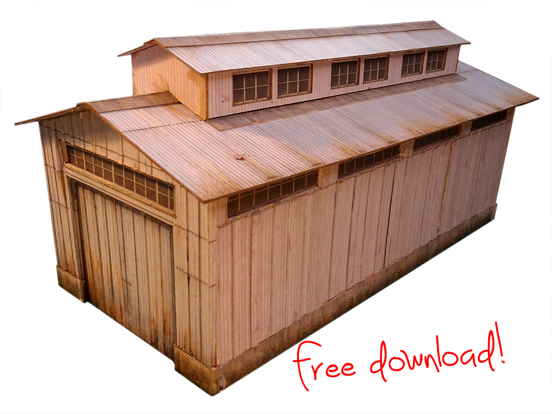
Need buildings for your layout? Have a look at the store.
They are great fun to make and great value too.