Richard’s been back in touch with his update on building a railroad helix – it’s a fantastic narrative:
“This begins a story that covers 35 years. I started designing this railroad in the early 1970s based on my love of train layouts I had as a child and began construction in the latter part of the 1970s.
My childhood involved S Gauge American Flyer trains but this project had to be more than just a circle of track on a 4 foot by 8 foot layout so I chose to build my current train in N Gauge to allow for a more realistic model in essentially a 2.5 x 8 foot space.
The plan was to have block and sector control for almost every 3 feet of track from a control panel with multiple DPDT rocker switches with a center off position. This concept predated many of the advanced control systems of today. This allowed for multiple power supplies to service up to three trains simultaneously.
The railroad concept was to be a logging and coal distribution layout from the forest and stone quarry at one end and coal mines at the other end to a distribution yard location in the middle section.
It would have passenger service provided to move workers to the forest and mine locations as well as a through route to distant cities. The railroad is an extended helix design that travels from one end of the layout to the other while rising in elevation to service the two industries.
The railroad project was photographed throughout the construction phases to highlight the elements added in each phase. A layout sketch is shown in Figure 1 and the actual control panel is shown in Figure 2.

Figure 1 control panel sketch shows turnout controls at the top and bottom and block and sector switches placed throughout the layout. dotted lines show track in tunnels.
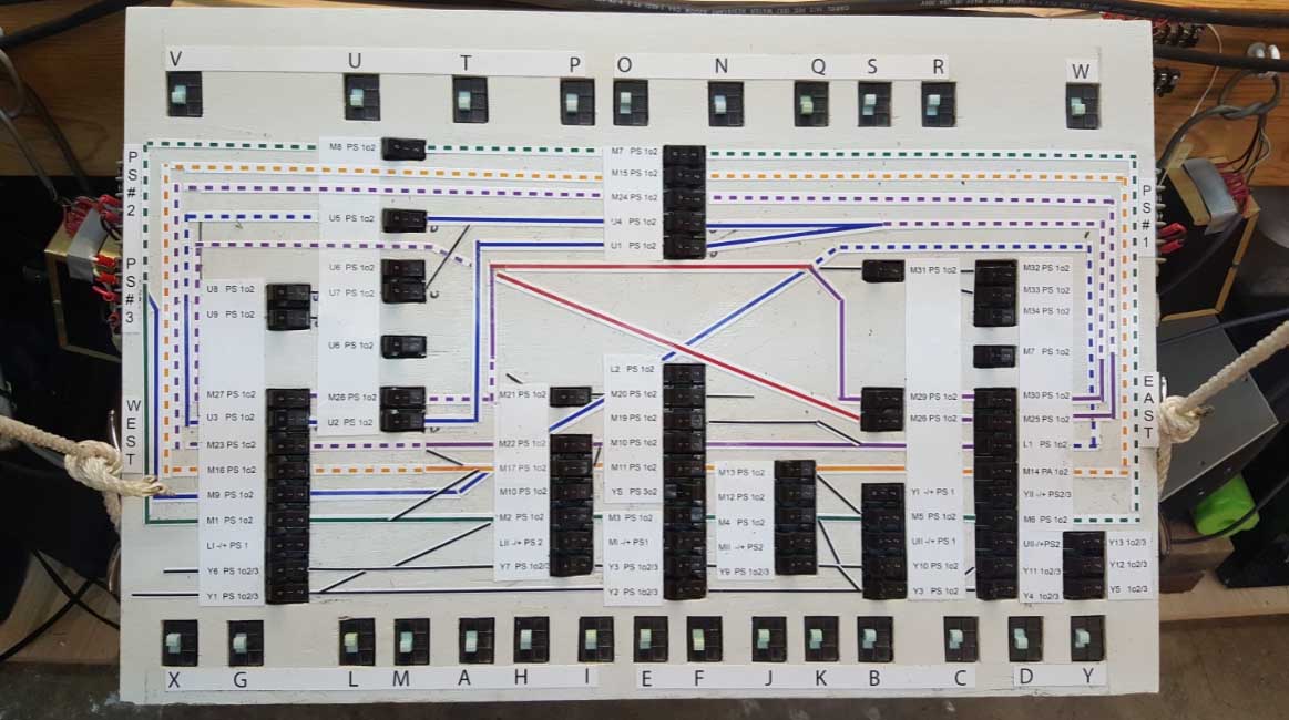
Figure 2 shows the actual control panel. the green, blue, orange, purple labeled tracks are stacked above each other in the upper tunnel areas to conserve lateral space.
A number of lighting features and turnout labels on the actual right of way would be added later.
The first construction project on the railroad was to build two wooden high mountain trestles to span a open valley as one of the central themes. It was designed and constructed as two balsa wood structures built from scratch resembling high mountain structures of the 1930s and 1940s in the US.
I built the two long bridges in Figure 3 by estimating the span based on the railroad plan and sketch I had settled on much earlier.
The upper shelf in Figure 4 shows the planned location for the stone quarry and logging and lumber cutting industrial site. A vertical panel is planned for the back side of the entire layout and would be removable to access tracks for maintenance within the mountains in case of derailment.
The upper shelf in Figure 5 shows the planned location for the coal mining operation. Figure 6 shows the back side of the layout with the cover panel removed. Tracks are stacked as part of the extended helix configuration and the block and sector wiring is routed and taped to the vertical risers that support the tracks.
At this stage of the building construction, train and turnout operation was checked before adding screening and plaster scenery so corrections to the layout could be made without undue disassembly.
Unfortunately, career obligations, vacations to most of the US National Parks and biking for rails-to-trails recreation limited the time available to continue the railroad construction for at least 30 years until I retired.
After retirement, I was eager to begin working on the model railroad again. The delay, however, caused excessive track corrosion which impacted train operation. Track cleaning was taken on as a major unplanned event and seemed to solve the continuity problem and I moved on to creating my empire.
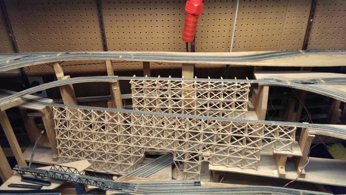
Figure 3 trestles located in the middle of the layout with no screen or plaster scenery.

Figure 4 shows a shelf on the left side of the layout for the logging and lumber industry. a cavity beneath the railroad contains the wiring for all tracks and features.
Building a railroad helix:
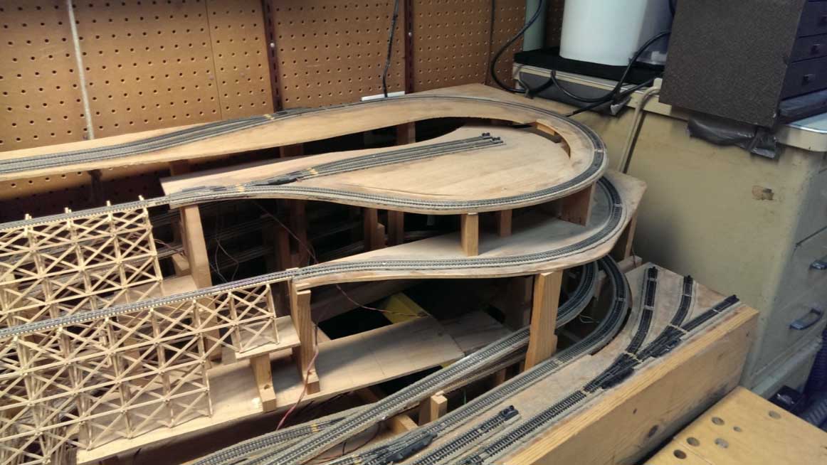
Figure 5 shows a shelf on the right side of the layout for the coal mining operation.

Figure 6 shows how the tracks are stacked at the back side of the layout before installing the back panel.
Nylon screening was chosen to support the plaster and was screwed to free standing support posts and to the existing railroad superstructure as shown in Figure 7, 8 and 9.
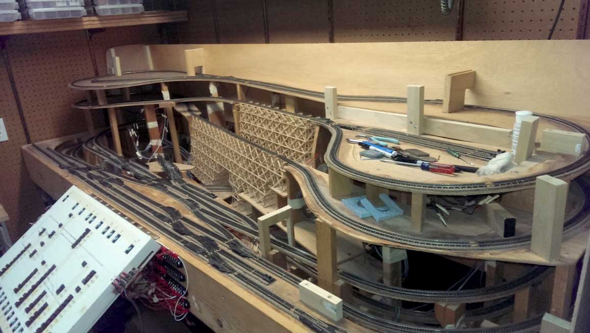
Figure 7 support posts for the screen and plaster
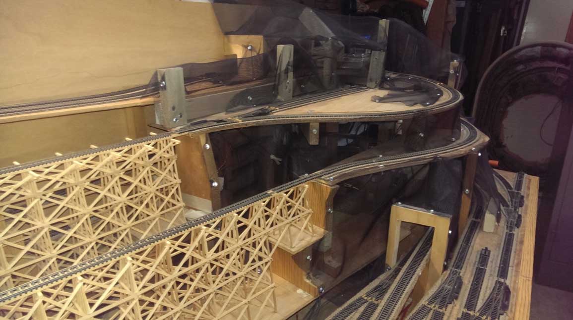
Figure 8 coal mining region with screen mesh in place.
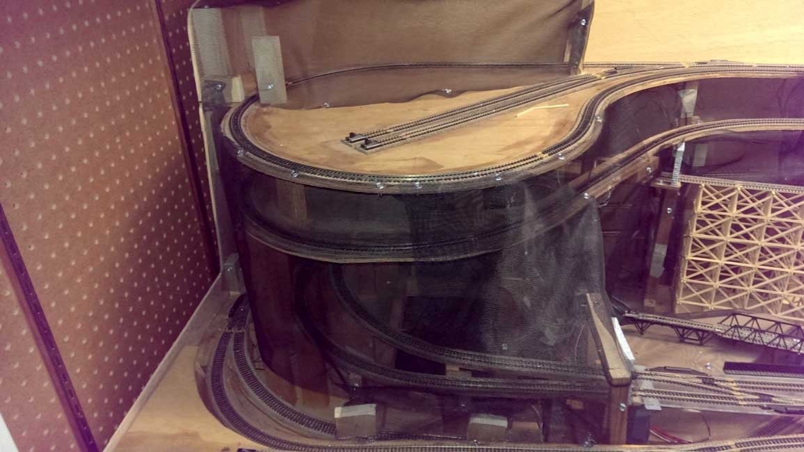
Figure 9 Railroad stone quarry and forest logging and lumber region with screen mesh in place.
About 40 pounds of uncolored plaster was added over several months to give the railroad a mountainous terrain as shown in figures 10, 11 and 12.

Figure 10 Building the stone quarry and forest logging and lumber region with plaster in place.
Building a railroad helix:

Figure 11 railroad coal mining region with plaster in place.
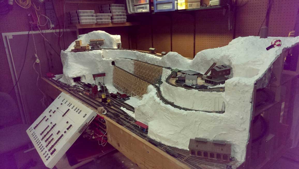
Figure 12 complete railroad with plaster in place.
Ground color, buildings and selected regions of grass, bushes and trees were added to bring the railroad closer to a final presentation.
Figure 13 shows the completed stone quarry, forest logging and lumber cutting industry. A shipping dock and crane tower were added to facilitate movement of raw and cut lumber. A small rail station and hotel service the workers at this industrial site. T
he log saw mill is high on the mountain top along with a green seemingly water tower on Lambs Knoll. Lighting has been added for a night operation.
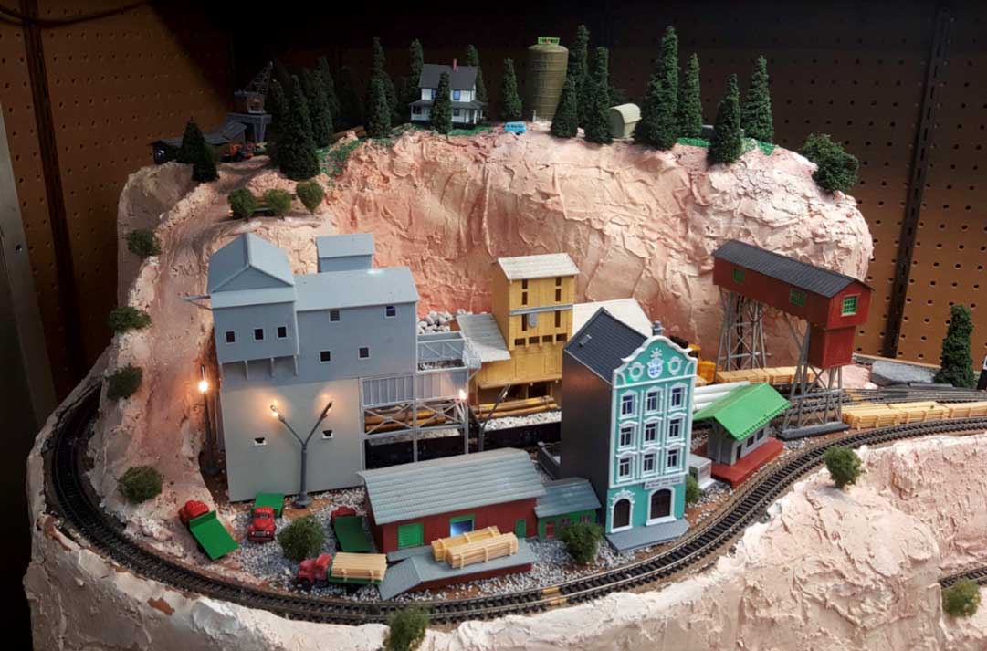
Figure 13 a stonequarry, forest logging and lumber processing region.
The trestle bridges were stained a more reasonable burnt orange as shown by Figure 14.
A coaling tower and coal dump station were added in Figure 15 to the yard location with an unlikely covered bridge to allow heavy trucks to move to either site. Colored posts were added to each turnout location as labels identical to that on the control panel for ease of operation.
Rail cars have found their way into the yard at Trestle Junction.
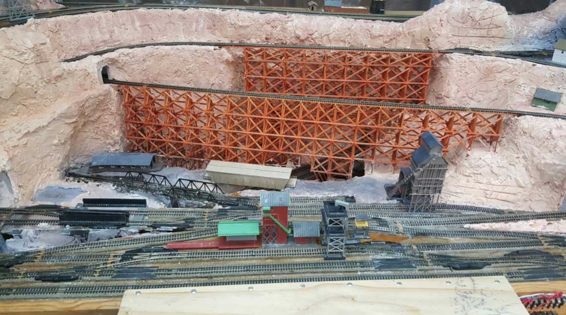
Figure 14 stained railroad tressles

Figure 15 railyard and coal processing region at trestle junction.
Figure 16 shows the coal mining region. It started out with a small coal mining operation and soon flourished into a major coal processing facility accompanied by a general store, hotel and rail station to service the mine workers.
The white tower at the far left in Figure 16 is a hardened but abandoned microwave relay antenna tower at Cross Mountain. Tropo-scatter communication antennas are shown on the right side of Figure 16 for the Hearthstone Mountain facility.
The radar dome was added for color but does not exist in the real environment just like the actual coal mining facility due to the high
power transmitting site. Lighting has also been added to the night time operation of the modeled coal mining facility.
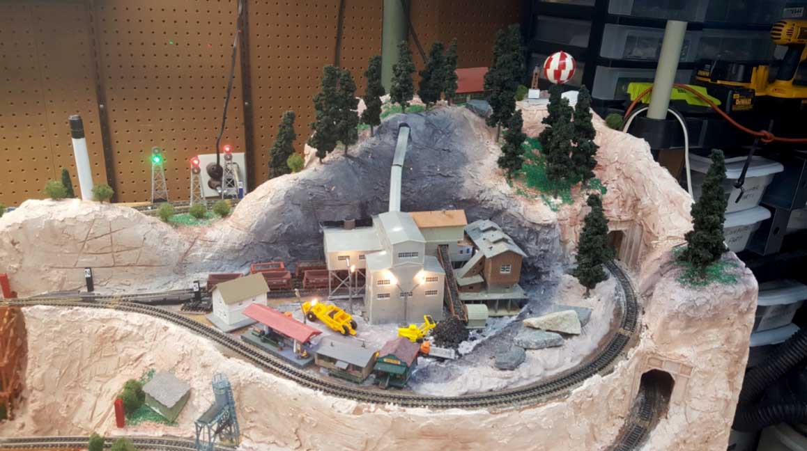
Figure 16 coal mining operation and lighted turnout signal towers
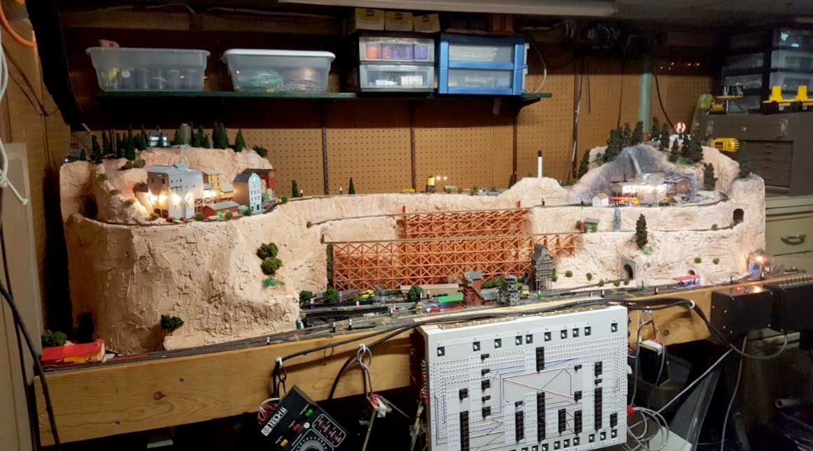
Figure 17 extended helix railroad with lighted features.
Figure 17 also shows the completed railroad. Track conductivity was again becoming a problem and the cleaning process is now more difficult even with access to the tunnels.
Building a railroad helix Phase II
The Extended Helix Railroad design is being modified to include another 2.5’ by 4’ section beyond the coal mining facility but at a lower level to enable trains to change direction without traveling to the top of the mountain and back down, a short coming in the original design.
The design of this modification is shown in Figure 18
The original extended helix and in Figure 19, the extended helix railroad with an extension on the right-hand side.

Figure 18 the original extended helix railroad

Figure 19 Building a railroad helix – extension on the right-hand side.
Building a railroad helix:
I found that I could use a drawing program i.e. Microsoft Visio to develop the train layouts. The software program was not made for this purpose specifically but could easily be adapted for this application. Figure 19 shows how I was planning to extend the Original Extended Helix Railroad.
Figures 18 and 19 are displayed in two different scale dimensions. The extension is 30” by 48” to match the width of the Original Extended Helix Railroad. The diagram in Figure 18 includes labels indicating track radius with parts of the circumference identified as 15-, 30- and 90- degree segments.
This is a typical dog bone design. The diagram also includes elevation markers, for example L10” above L0” which is 10” above 0” at the railroad yard. The colors represent the original block segments needed for sector power control of the original DC railroad and to help visualize which elevation marker goes with each level of track.
Figure 19 is a diagram of the planned 4’ extension to the Extended Helix Railroad. As noted in the diagram, track elevation markers were identified but I had not gotten around to adding the track radius and circumference designations.
Bridge locations were identified where the stream and waterfall needed to be crossed. Since the railroad yard was established as L0” in the Original Extended Helix Railroad references could then be + or – elevations to that reference.
I found that I was creating a difficult construction project which had similar elevation rise problems that I had created in the original railroad. I had fallen into that same trap of trying to force an engine to climb a steep slope.
The engines were able to climb the slope alone but not with cars, another misfortune.
Figure 20 Adjustable Riser Concept explains my latest track support mechanism. I had originally used “U” shaped risers to support the elevated track in the Original Extended Helix Railroad shown in Figure 6 but found that additional adjustments had to be made in either elevation or horizontal movement to get the correct elevation height.
Hopefully the Adjustable Risers will solve the elevation adjustment problem. The parts cost for each riser is a downside to using the Adjustable Riser Concept and has been set aside until the actual building process begins.

Figure 20 adjustable riser concept
Before the Righthand Railroad Extension had been implemented, another plan was being considered as an alternative extension to the Original Extended Helix Railroad. Figure 21 Lefthand Railroad Extension was drawn for comparison.

Figure 21 lefthand extension to the original extended helix railroad
I have found that designing railroads on paper until the best compromise can be achieved is always better since no materials have been expended.
The Lefthand Extension to the Original Extended Helix Railroad offered a less congested approach for the modification and only required the trains to run up a 2% grade which is an improvement over the Original Extended Helix Railroad. Each loop in the Lefthand Extension decreases by approximately 2 inches as shown by the L0, L-2, L-4 etc.
The river and waterfall are not yet shown but are planned to pass beneath the turnouts and bridges from each loop.
Two tracks at L0 will come together and enter the Original Extended Helix Railroad at the Yard Tracks and Level L-10 through L-16 will enter the Original Extended Helix Railroad beneath the entire railroad and form loops to return to the Lefthand Extension and rise up in each consecutive loop to level zero.
Loops at level L0, L-2 through L-8 are consecutively stacked below the previous loop and L-10 through L-16 deviate to the right over the bridges. The Microsoft Visio program allows the drawing to be magnified from 50% to 400% to examine more closely the displayed tracks for better clarity.
The multiple loops contained beneath the Original Extended Railroad caused an additional complication. The Original Extended Railroad will need to be raised on stilts above the loops passing beneath the Original Extended Railroad.
Progress has been one step forward and two steps back and has become a real challenge. The Original Extended Helix Railroad has tracks that rise 12” above the Railroad Yard and the Lefthand Extension to the Original Railroad has tracks 16” beneath the Railroad Yard for a total of 28”. Poor stability has become an undesirable trait.
Track conductivity was documented in the Phase I discussion as being the number one problem for a congested railroad with hidden tracks within mountainous regions and having poor access to the many track levels.
I had thought I had solved the track cleaning problem by removing a safety panel from the back side of the railroad to gain access to the many track levels, but cleaning tracks spaced above each other by only 2” with “U” channel supports was not ideal and the panel had to be reinstalled after each cleaning to restore safety. Operating the railroad without the safety panel can cause trains to fall from the railroad to the floor if the train derails.
The deterioration of the track conductivity has led to a bold step into the future of model railroading. Research has led to the concept of battery power for train operation to solve the track conductivity problem.
“N” gauge is quite small and limiting when trying to shoehorn in a battery power system into freight and passenger cars to electrify the engine motor when the battery cannot be directly integrated in a steam or diesel locomotive.
“HO” gauge and larger trains are better suited to installing batteries for operation but there is a tradeoff to be considered. Bigger gauges require more power and recharging becomes more frequent. A control chip and speaker must also find their way into the tender of the steam locomotive or into the “B” unit of a diesel locomotive.
Both the steam locomotive’s tender and the “B” diesel unit must be permanently connected together along with the additional battery powered freight or passenger cars. This means the train must always be configured with at least two or more battery powered cars.
Lithium-Ion B size batteries have been made small enough to package two batteries into two passenger cars for a passenger train and must be configured in two freight cars or two flat cars for a freight train.
Figure 22 shows Four batteries in series are required for at least a 14.8 Volt at nominally 3.5 A/hour. A Hand Controller must radiate the signal that controls the pulse width modulation used by the motor in the locomotive to efficiently control the use of battery power without using the track for power.
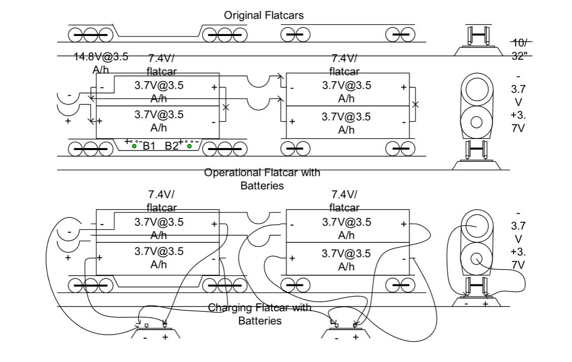
Figure 22 example of “n” gauge railroad flat cars with “b” size li batteries
15V Passenger Baggage Car and Freight Flat Car Battery Supply.

7.5V Passenger Baggage or Freight Flat Car Battery Supply 1 of 2
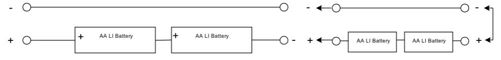
Figure 23 examples of “n” gauge railroad flat cars with “aaa” and “aa” series li batteries
The multiple Lithium-Ion (LI) battery configurations are set up to transfer power to a control car and locomotive or be charged with two batteries in series at 7.5V without removing the batteries from the railroad cars.
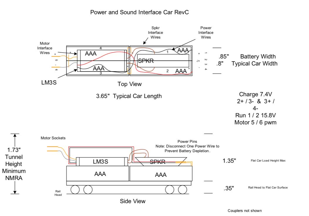
Figure 24 latest battery configuration for a railroad flat car with a controller chip
Lithium-Ion Batteries have been procured for a 3.7 V per cell at 1.8 A/hour rating and a speaker for sound realism. Several LM3S control chips were procured from Ring Engineering along with a Handheld Controller.
Military grade connector pins have been purchased to conveniently connect the car together and charge the batteries when needed.
Building a railroad helix Phase III
I stated in Phase II that I was planning an extension to the existing Logging and Coal Mining Model Railroad shown in Figure 19. The design evolved into a right-angle section as shown in Figure 21. I wanted to create a waterfall scene with multiple railroad bridges passing in front of the falls and providing a turnaround track for the trains without traveling up the mountain as described in Phase II.
You have probably noticed that there have only been drawings in Phase II and no pictures. The design was completed as described but the actual railroad extensions were not created. Since the grade problem in the Original Extended Helix Railroad was not resolved and since the railroad might have to be moved in the future where less space is available, a new approach is being developed.
The Original Extended Helix Railroad components were removed, and the basic railroad structure was destroyed. A new railroad has been designed and I will soon begin construction. This railroad will be known as a switching railroad to minimize the space required. The railroad will be 18” deep by 120” in length consist of two levels separated by 12”. A plan view is shown in Figure 25.
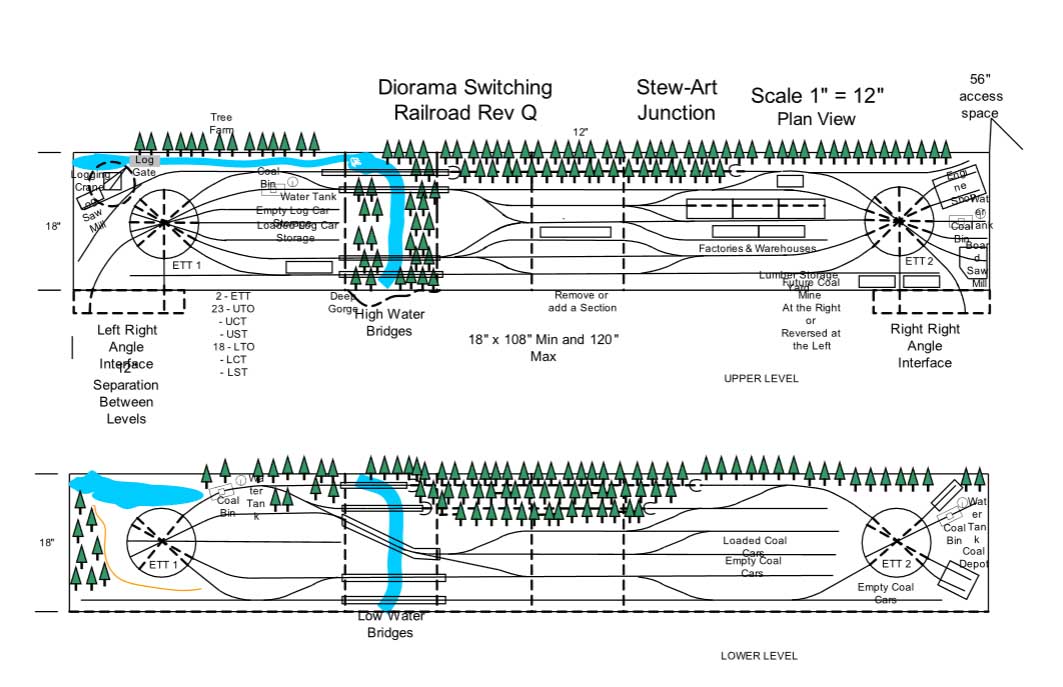
Figure 25 diorama switching railroad
The basic switching railroad will be 18” by 120” to fit in a standard room without modifications. The railroad upper level has been designed to accommodate a right-angle section that can be placed at either end to extend the railroad along another wall where no doors or closets interfere with the layout as shown in Figure 26.
The right-angle extension applies only to the upper level of the basic railroad. Both upper and lower segments have a section that can be removed if the length exceeds the available space.

Figure 26 left or right extension to the diorama switching railroad
Figure 26 shows an extension of the basic railroad to be created if desired. Figure 27 shows an elevated display of the joined bi-level railroad. Both the upper and lower levels are to be 18” deep and 120” in length.
A unique design feature of this railroad has a turntable at both ends and even more unique each turntable rotates to deliver the engine and one car to the desired track. A further feature allows the turntable to travel from the upper to the lower level as shown in Figure 27.
A final Figure 28 shows a diagram of the Turntable. It does not exist in the real world but allows the Engine and one car to be transported between the levels at both ends of the railroad. The dual turntable allows an engine and one car to be moved between levels at either end of the railroad. Pictures will be provided as they become available.
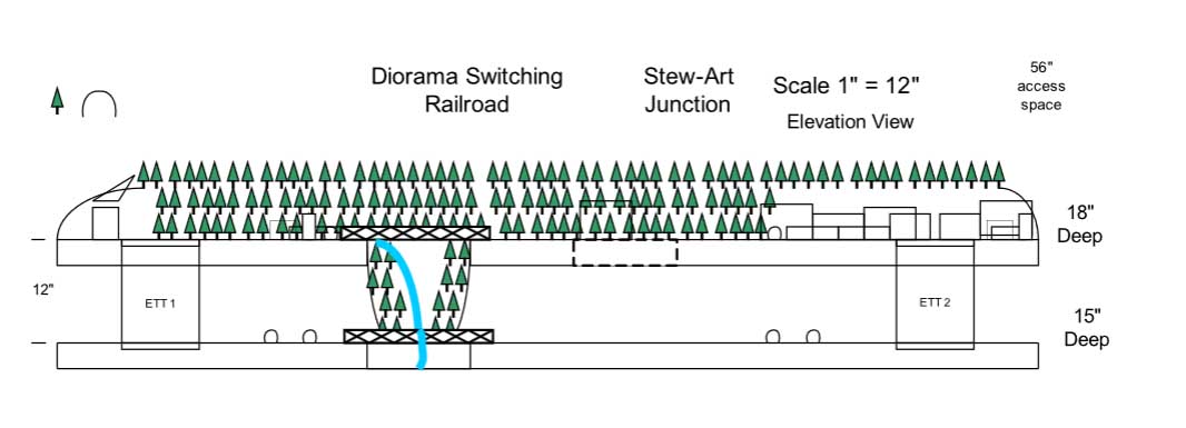
Figure 27 elevation view of the upper and lower switching railroad levels
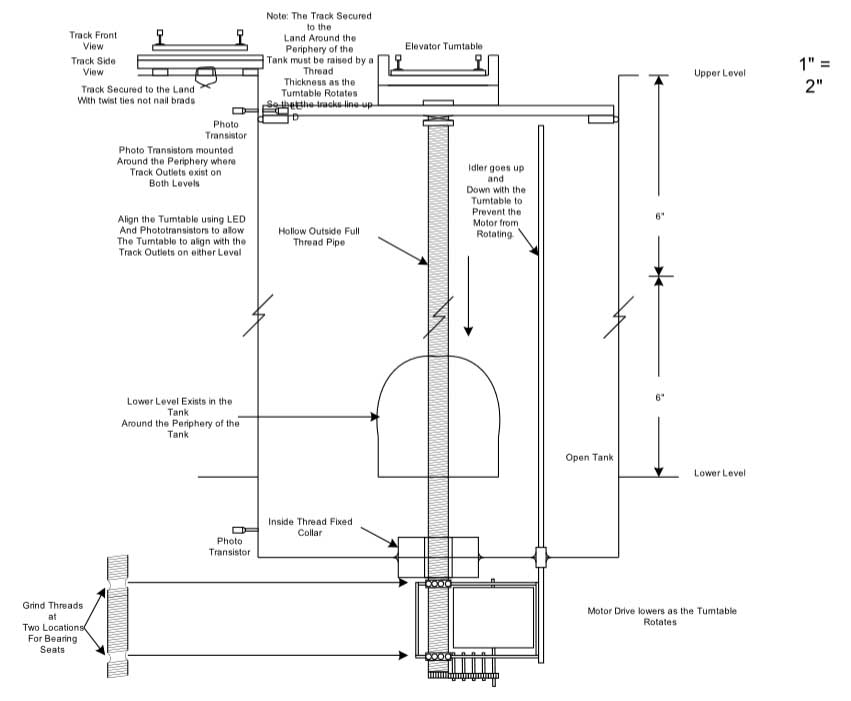
Figure 28 elevated turntable to transfer an engine and one car between levels
A huge big thank you to Richard for taking the time and trouble to put together his update on building a railroad helix. I do love a good narrative, and it’s great to see the problems and solutions that crop up in a layout.
I’m so looking forward to Richard’s next update, whenever that may be.
Over the years, there have been many posts on building a railroad helix – here’s a few more of them:
How to build a model train helix
That’s all for today folks.
Please do keep ’em coming.
And if today is the day you decide to get building a railroad helix or just a simple oval, the Beginner’s Guide is here.
Best
Al
PS Latest ebay cheat sheet is here.
PPS More HO scale train layouts here if that’s your thing.

extremely cool bridges.
I appreciate fellow modelers documenting all the steps in creating their layouts, large and small. Proof that patience is a key element in this hobby. And that things we think we could never do, end up being things we can do!
Couldn’t ask for anything better with compressed linear design than this. Masterful goings on here. It’s only the finished project kinda resembles a tiered wedding cake. Mountainous risers maybe a bit too vertical and omit a lot of detailing? Way too much human presence, crowding in of structures. Use them if you have them, I would probably do same. Surface mount switch solenoids, just an acceptable way of life as I see it even today.
It’s just that I anticipated something different other than finished outcome. Now, could I do this or any better?? Absolutely no, I wouldn’t even attempt. Even so, this is the perfect size, theme and even quality of craft still of coarse.
Redarding, Rich
Richard, what a great job of explaining and detailing the process. Thank you
Richard
Wow! Narrative is awesome and well received. Your honest expose served us all admirably as to pitfalls we may run into. What I dont know is did you go “Deadrail” and if so how do like it. What are the pros & cons.
Phase 1 can still be both hot rail and Deadrail and did you try that No-OX-ID system? If your track is old & pitted it may require a tedious repair with wet/dry paper or compound (you dont want to be too aggressive here) before you apply a microscopic film amount of NO-OX with your finger tip. Many claim wonders with this and a few dont but what do you have to lose ( stuff aint cheap but will last a lifetime).
At any rate please let us know what you are up to. Love that bridge.
Big Al
Lot of stuff to digest in this one. Fabulous. Much thanks.
Now that’s a thorough explanation of the process! Perhaps we can call you Wiki-Richard?!!